EP1100582B1 - Pemf-vorrichtung zur behandlung der osteoporose und zur stimulation des wachstums von geweben - Google Patents
Pemf-vorrichtung zur behandlung der osteoporose und zur stimulation des wachstums von geweben Download PDFInfo
- Publication number
- EP1100582B1 EP1100582B1 EP99937623A EP99937623A EP1100582B1 EP 1100582 B1 EP1100582 B1 EP 1100582B1 EP 99937623 A EP99937623 A EP 99937623A EP 99937623 A EP99937623 A EP 99937623A EP 1100582 B1 EP1100582 B1 EP 1100582B1
- Authority
- EP
- European Patent Office
- Prior art keywords
- pad
- patient
- transducer
- transducer coil
- drive signal
- Prior art date
- Legal status (The legal status is an assumption and is not a legal conclusion. Google has not performed a legal analysis and makes no representation as to the accuracy of the status listed.)
- Expired - Lifetime
Links
- 230000000638 stimulation Effects 0.000 title claims description 10
- 208000001132 Osteoporosis Diseases 0.000 title description 8
- 230000008467 tissue growth Effects 0.000 title 1
- 230000005672 electromagnetic field Effects 0.000 claims abstract description 27
- 230000004044 response Effects 0.000 claims abstract description 11
- 238000000940 electromagnetic therapy Methods 0.000 claims abstract description 9
- 210000000988 bone and bone Anatomy 0.000 claims description 52
- 229910052500 inorganic mineral Inorganic materials 0.000 claims description 50
- 239000011707 mineral Substances 0.000 claims description 50
- 210000003141 lower extremity Anatomy 0.000 claims description 15
- 210000001364 upper extremity Anatomy 0.000 claims description 15
- 239000000463 material Substances 0.000 claims description 14
- 210000003414 extremity Anatomy 0.000 claims description 12
- 230000004907 flux Effects 0.000 claims description 11
- 210000000707 wrist Anatomy 0.000 claims description 10
- 210000003423 ankle Anatomy 0.000 claims description 7
- 210000000115 thoracic cavity Anatomy 0.000 claims description 5
- 210000004394 hip joint Anatomy 0.000 claims description 4
- 210000002414 leg Anatomy 0.000 claims description 4
- 238000012544 monitoring process Methods 0.000 claims description 4
- 210000000689 upper leg Anatomy 0.000 claims description 4
- 239000006263 elastomeric foam Substances 0.000 claims description 3
- 239000012260 resinous material Substances 0.000 claims description 3
- 238000012163 sequencing technique Methods 0.000 claims description 3
- 239000013536 elastomeric material Substances 0.000 claims description 2
- 229920002554 vinyl polymer Polymers 0.000 claims description 2
- 238000000034 method Methods 0.000 abstract description 4
- 230000004936 stimulating effect Effects 0.000 abstract 1
- 238000002560 therapeutic procedure Methods 0.000 description 15
- 206010017076 Fracture Diseases 0.000 description 12
- 230000015654 memory Effects 0.000 description 12
- 238000011084 recovery Methods 0.000 description 9
- 238000013461 design Methods 0.000 description 8
- 238000012360 testing method Methods 0.000 description 7
- 238000004804 winding Methods 0.000 description 7
- 230000008901 benefit Effects 0.000 description 6
- 208000010392 Bone Fractures Diseases 0.000 description 5
- 238000013459 approach Methods 0.000 description 4
- 239000003990 capacitor Substances 0.000 description 4
- 238000010276 construction Methods 0.000 description 4
- 238000013523 data management Methods 0.000 description 4
- 238000001514 detection method Methods 0.000 description 4
- 238000010586 diagram Methods 0.000 description 4
- 230000000284 resting effect Effects 0.000 description 4
- 208000027418 Wounds and injury Diseases 0.000 description 3
- 230000000881 depressing effect Effects 0.000 description 3
- 230000006870 function Effects 0.000 description 3
- 230000004927 fusion Effects 0.000 description 3
- 210000001624 hip Anatomy 0.000 description 3
- 230000035515 penetration Effects 0.000 description 3
- 230000000007 visual effect Effects 0.000 description 3
- WHXSMMKQMYFTQS-UHFFFAOYSA-N Lithium Chemical compound [Li] WHXSMMKQMYFTQS-UHFFFAOYSA-N 0.000 description 2
- 208000001164 Osteoporotic Fractures Diseases 0.000 description 2
- 230000008859 change Effects 0.000 description 2
- 238000004891 communication Methods 0.000 description 2
- 210000002683 foot Anatomy 0.000 description 2
- 229910052744 lithium Inorganic materials 0.000 description 2
- 210000002346 musculoskeletal system Anatomy 0.000 description 2
- 239000004033 plastic Substances 0.000 description 2
- 229920003023 plastic Polymers 0.000 description 2
- 230000000630 rising effect Effects 0.000 description 2
- 230000006403 short-term memory Effects 0.000 description 2
- 241000112853 Arthrodes Species 0.000 description 1
- 206010020100 Hip fracture Diseases 0.000 description 1
- 206010031264 Osteonecrosis Diseases 0.000 description 1
- 208000004210 Pressure Ulcer Diseases 0.000 description 1
- 208000000491 Tendinopathy Diseases 0.000 description 1
- 208000021945 Tendon injury Diseases 0.000 description 1
- 206010043255 Tendonitis Diseases 0.000 description 1
- 206010048049 Wrist fracture Diseases 0.000 description 1
- 238000009825 accumulation Methods 0.000 description 1
- 230000003213 activating effect Effects 0.000 description 1
- 230000004913 activation Effects 0.000 description 1
- 230000009286 beneficial effect Effects 0.000 description 1
- 230000037182 bone density Effects 0.000 description 1
- 230000001684 chronic effect Effects 0.000 description 1
- 230000001186 cumulative effect Effects 0.000 description 1
- 230000007423 decrease Effects 0.000 description 1
- 239000003814 drug Substances 0.000 description 1
- 230000000694 effects Effects 0.000 description 1
- 239000006260 foam Substances 0.000 description 1
- 210000000245 forearm Anatomy 0.000 description 1
- 229920001702 kydex Polymers 0.000 description 1
- 210000003041 ligament Anatomy 0.000 description 1
- 210000004705 lumbosacral region Anatomy 0.000 description 1
- 239000002991 molded plastic Substances 0.000 description 1
- 230000011164 ossification Effects 0.000 description 1
- 230000001009 osteoporotic effect Effects 0.000 description 1
- 230000002265 prevention Effects 0.000 description 1
- 230000008569 process Effects 0.000 description 1
- 230000001737 promoting effect Effects 0.000 description 1
- 230000009467 reduction Effects 0.000 description 1
- 238000009256 replacement therapy Methods 0.000 description 1
- 238000005070 sampling Methods 0.000 description 1
- 239000004065 semiconductor Substances 0.000 description 1
- 210000004872 soft tissue Anatomy 0.000 description 1
- 206010041569 spinal fracture Diseases 0.000 description 1
- 230000002195 synergetic effect Effects 0.000 description 1
- 201000004415 tendinitis Diseases 0.000 description 1
- 229920001169 thermoplastic Polymers 0.000 description 1
- 125000000391 vinyl group Chemical group [H]C([*])=C([H])[H] 0.000 description 1
Images


Classifications
-
- A—HUMAN NECESSITIES
- A61—MEDICAL OR VETERINARY SCIENCE; HYGIENE
- A61N—ELECTROTHERAPY; MAGNETOTHERAPY; RADIATION THERAPY; ULTRASOUND THERAPY
- A61N2/00—Magnetotherapy
- A61N2/02—Magnetotherapy using magnetic fields produced by coils, including single turn loops or electromagnets
Definitions
- the present invention relates generally to a PEMF stimulator for treating osteoporosis and other medical conditions by promoting an increased bone mineral content and density.
- Therapeutically difficult problems of the musculoskeletal system include spinal fusion, un-united fractures (or non-union fractures), failed arthrodeses, osteonecrosis, and chronic refractory tendinitis, decubitus ulcers and ligament, tendon injuries, osteoporosis, and Charcot foot.
- Such problems, especially fractures may result from losses in bone mineral density.
- Osteoporosis in particular is responsible for 1.5 million fractures in the U.S. annually, especially hip, vertebral and wrist fractures.
- One conventional approach for treating such fractures is pharmaceutical therapy. This approach is disadvantageous because such therapy is generally expensive, and lasts for a patient's lifetime. Furthermore, such therapy may be associated with side effects which some patients may not tolerate.
- Pulsed electromagnetic fields are low-energy, time-varying magnetic fields that are useful for treating such problems of the musculoskeletal system.
- an electromagnetic transducer coil is typically placed in the vicinity of the fracture or fusion such that pulsing the electromagnetic transducer will produce an applied field that penetrates to the underlying bone.
- a conventional approach is to use a flat oval-shaped transducer coil for PEMF fracture therapy.
- This approach is disadvantageous because the transducer coil may not cover the entire treatment area and the applied field has limited penetration.
- a second coil design for spinal fusion incorporated both a primary coil and a secondary coil to provide broad field coverage inside a defined treatment volume. Accordingly, providing effective PEMF fracture therapy using a flat coil design with broad field coverage and good field penetration required a new coil and drive circuit design which permits the use of only a single, more compact and energy efficient coil.
- This design is described in detail in U.S. Patent 5,743,844, entitled High Efficiency Pulsed Electromagnetic Field (PEMF) Stimulation Therapy Method and System.
- One aspect of the present invention includes a bone mineral density (BMD) stimulator for osteoporotic patients.
- the stimulator for this embodiment may sometimes be referred to as a PEMF stimulator or Osteoporosis stimulator.
- the stimulator generates a pulsed electromagnetic field (PEMF) which induces voltages and current to provide non-invasive treatment to increase bone mineral density (BMD).
- the pulsed electromagnetic field generated by the bone mineral density stimulator provides a non-invasive treatment for osteoporosis.
- the signal is preferably of a similar frequency as that delivered by commercially available stimulators which have been clinically demonstrated to affect bone formation. The signal offers greater energy efficiency than many current commercial PEMF devices.
- a flat coil design with broad field coverage and good field penetration permits the use of only a single coil, and results in a compact and more energy efficient coil to produce such a pulsed electromagnetic field, as is described in U.S. Patent 5,743,844.
- Use of such a design can be advantageous in treating many areas at high risk for fractures due to osteoporosis. Such areas include, but are not limited to, the thoracic and lumbar spine, femoral head, neck, and the upper and lower extremities.
- At least two such coils may be disposed in a pad in at least one layer of elastomeric material.
- the pad may include a polymeric material that may be deformed to assume various configurations and/or to provide support.
- an additional coil may be disposed in an extremity pad.
- DE 9 300 499 U discloses an electromagnetic therapy device comprising first and seconder transducer coils connectables to a driving circuit.
- Technical advantages of the present invention include using PEMF therapy to increase bone density to a level that substantially decreases a patient's risk of fracture. For example, treatment over a broad field that would encompass all areas of bone particularly prone to osteoporotic fracture, including but not limited to areas such as the hip, spine and wrists, would be beneficial in increasing bone mineral density and/or content, thereby preventing osteoporotic fracture.
- Another technical advantage includes a synergistic effect when PEMF therapy is used in combination with pharmaceutical therapy.
- Yet another technical advantage includes using PEMF therapy to provide a patient a single daily treatment to simultaneously treat areas subject to fracture. The cost of such PEMF therapy is substantially reduced as compared to the cost associated with pharmaceutical treatment of osteoporosis. Such PEMF therapy may provide a suitable replacement therapy for patients who cannot be treated with pharmaceuticals.
- a bone mineral density stimulator incorporating teachings of the present invention may be used for prevention of hip, spinal, wrist and/or other fractures.
- Further technical advantages of the present invention include producing an energy efficient PEMF signal with pulse width between ten microseconds (10 ⁇ sec) and twenty microseconds (20 ⁇ sec). For some applications, a bone mineral density stimulator producing a PEMF signal with pulse widths of approximately sixteen microseconds (16 ⁇ sec) will be very energy efficient.
- FIGURES 1A-10C of the drawings in which like numerals refer to like parts.
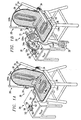
- Bone mineral density stimulator 30 incorporating teachings of the present invention is shown in FIGURE 1A secured to chair 20.
- Bone mineral density stimulator 30 produces electrical signals similar to Spinal-Stim® Lite devices that are offered by Orthofix.
- bone mineral density stimulator 30 includes a control unit or housing 50 sending a programmed signal to at least two transducer coils 104s and 104b.
- the PEMF signal generated by bone mineral density stimulator 30 may consist of a burst of one thousand six hundred nine (1609) pulses, at a repetition rate of one and one-half (1.5) pulse bursts per second.
- Each individual pulse consists of a positive (energization) portion, four microseconds (4 ⁇ sec) wide, and a negative (de-energization) portion, approximately twelve microseconds wide (12 ⁇ sec).
- the amplitude of the positive portion is about three times the amplitude of the negative portion.
- Bone mineral density stimulator 30 is designed to provide a uniform magnetic field and constant peak flux densities throughout the volume of the treatment site.
- bone mineral density stimulator 30 includes pad 32 and control unit or housing 50.
- Pad 32 preferably includes first portion 36 having a configuration corresponding with seat 22 of chair 20 and second portion 38 having a general configuration corresponding with back 24 of chair 20.
- pad 32 may have an approximate length of forty-four inches (44") and width of approximately twenty-one inches (21").
- First portion 36 may be flexibly coupled to second portion 38.
- pad 32 is releasably secured to chair 20 by flexible straps 34.
- Pad 32 may be releasably secured to chair 20 in other embodiments by other suitable means (not expressly shown) located at any suitable location on pad 32.
- Such securing means include, but are not limited to, additional straps 34, an elastic slip cover, or straps that secure with buckles or Velcro® closures.
- Other embodiments are also within the scope of the invention.
- pad 32 is portable, and can also be used by a patient in a more horizontally-oriented position, such as in a reclining chair.
- Pad 32 may also be placed on other suitable surfaces such as, for example, a table, bed, or sofa. Positions for treating patients placed with their backs at angles ranging from fifteen (15°) degrees in the forward position to forty five (45°) degrees in the backward or reclining position are especially advantageous in treating patients.
- At least one transducer coil designated 104s is disposed in first portion or seat portion 36 of pad 32.
- at least one transducer coil designated 104b is disposed in second portion or back portion 38 of pad 32.
- Bone mineral density stimulator 30 is preferably designed to treat the proximal femur, hip joint, lumbar and thoracic spine of female patients, ranging from the 5 th to 95 th percentile in size.
- transducer coils 104s or 104b that are operated by control unit 50 to be disposed in each of first portion 36 and second portion 38 of pad 32.
- back portion 38 of pad 32 may dispose a plurality of transducer coils 104b oriented vertically, to treat the spine area.
- Additional transducer coils may also be configured to treat other portions of a patient's body such as wrists or ankles or other soft tissue areas for which such treatment is desirable. Construction of pad 32 and transducer coils 104s and 104b are discussed in further detail in conjunction with FIGURES 2 and 3.
- Control unit or housing 50 as used in this embodiment is shown resting on table 26 in FIGURE 1A.
- Flexible cable 52 is provided to electrically connect housing 50 with transducer coils 104s and 104b.
- quick disconnect 54 may be provided in cable 52 between housing 50 and pad 32.
- Other suitable means for electronically connecting housing 50 to pad 32 may also be used.
- Control unit 50 of bone mineral density stimulator 30 preferably sends programmed electrical impulses to transducer coils 104b and 104s disposed in pad 32.
- Transducer coils 104b and 104s develop a pulsed electromagnetic field.
- transducer coils 104b and 104s deliver a non-invasive, low- energy, pulsed electromagnetic field (PEMF) to a selected treatment site or sites of the patient.
- PEMF pulsed electromagnetic field
- transducer coils 104s and 104b along with electrical drive signals provided by control unit 50 through flexible cable 52 are preferably selected to provide a relatively uniform magnetic field and relatively constant peak flux densities throughout a desired treatment volume.
- a treatment volume is discussed in further detail in conjunction with FIGURE 9.
- Control unit 50 will typically have an ON/OFF switch 56 which controls the operation of both transducer coils 104s and 104b. For some applications, two separate ON/OFF switches 56 and 58 may be provided to allow individually controlling transducer coils 104s and 104b. In this embodiment, control unit 50 also includes an additional switch (not explicitly shown) for controlling treatment information access. For one application, control unit 50 may have dimensions of approximately three and one-half inches (3.5") by five and one quarter inches (5.25") by one inch (1").
- indicator lights 60 may also be provided on control unit 50 to indicate operational status such as when treatment is in process, when treatment has been completed if a battery power source is low.
- Indicator lights 60 may comprise light emitting diodes (LEDs) that are easily visible in normal room lighting, from a distance of about three (3') feet.
- control unit 50 includes color-coded LEDs, whose functions are described below and in conjunction with Table I.
- Other embodiments may include an audio transducer to provide an audible alarm function, in addition to, or instead of indicator lights 60.
- an audio beep or buzzer may be defined as one second of sound followed by one second of silence.
- control unit 50 will contain a single nine (9) volt disposable lithium battery (not expressly shown). The battery is disposed within control unit 50 and accessible through a door (not explicitly shown) for replacement. Control unit 50 may be powered by any suitable battery or other standard power source.
- Control unit 50 is preferably operable to detect whether the battery is low. While the unit is ON, if a low battery condition is detected, treatment is terminated and the red LED will flash to indicate that battery replacement is required. Similarly, when the unit is ON, if the battery voltage drops below a battery shutdown threshold, control unit 50 will automatically turn OFF.
- a patient may depress ON/OFF switch 56 once.
- the green LED will flash during normal treatment, which in this embodiment last for a time of between two and eight hours. It is often particularly advantageous for the patient to use bone mineral density stimulator 30 for a continuing treatment time of four hours. To terminate treatment prior to device time out, the patient may depress ON/OFF switch 56 again.
- Table I lists visual and audio indications for one embodiment of the invention. For example, when a flashing LED alarm indication is activated, the LED flashes at a rate of approximately once per second. Normal Treatment in progress is indicated by a green LED continuously flashing at approximately once per second.
- bone mineral density stimulator 30 will preferably provide a preset amount of daily treatment.
- Control unit 50 is operable to turn itself off at the end of the preset amount of treatment in a day. Prior to turning itself OFF, control unit 50 will preferably beep for five seconds and flash the yellow LED five times. The patient will be notified by a continuous audible alert and a steady red LED should a field fault occur while treatment is in progress (see Table I). Field fault sensing circuitry is discussed in further detail in conjunction with FIGURES 4 and 6.
- Bone Mineral Density Stimulator Visual & Audio Indicators PATIENT MODE Indication Meaning All LEDs and Continuous Audible Alert for ⁇ 3 secs.
- Control unit 50 is preferably operable to execute a system integrity or power on self test (POST) during the power-up sequence.
- POST system integrity or power on self test
- This test may check the following parameters: Real time clock (RTC), Software and Memory Check sums. During this test, all LEDs and the buzzer turn on for approximately 3 seconds and then turn off. If this test fails, the patient may not start treatment. The yellow LED is lit, and an audio alarm may be sounded and remain on until control unit 50 is turned OFF.
- Bone mineral density stimulator 30 is operable to maintain patient compliance history on a daily and cumulative basis by tracking treatment time.
- control unit 50 may accumulate treatment time for the current day following the first fifteen minutes of treatment.
- Control unit 50 is preferably operable to track treatment time in five-minute increments up to 900 minutes (15 hours) total, with a minimum treatment time for accumulation of one (1) hour.
- Control unit 50 can track treatment duration for up to four (4) treatment sessions in one day.
- Control unit 50 is operable to retain the date of the first treatment day after shipment, defined as the first day control unit 50 is "ON" greater than one hour continuously. Similarly, control unit 50 is operable to determine from the calendar the quantity of total days and total hours of treatment since last clear.
- Control unit 50 utilizes a Real Time Clock 404 with a battery to provide standby power during battery changes to perform time tracking.
- control unit 50 is operable to store at least 117 days of patient usage information in a battery-backed data random access memory (RAM) 403. Details for a preferred embodiment of the electrical circuitry in control unit 50 are discussed in conjunction with FIGURE 4.
- RAM battery-backed data random access memory
- Control unit 50 disposes a hidden switch (not explicitly shown) that may be used by a physician to enter into Compliance Data Management Mode as indicated in Table I.
- Compliance Data Management Mode is accessed by depressing ON/OFF switch 56 and a logo switch (not explicitly shown) simultaneously and holding for three seconds. Exiting the Compliance Data Management Mode is performed by depressing ON/OFF switch 56 to power down control unit 50. Depressing the logo switch and holding for five seconds clears compliance memory 403.
- Control unit 50 provides a print mode of operation which enables the physician to request a printout of compliance data such as those indicated in Table II at any time during patient treatment.
- the print mode is initiated by pressing the logo switch on control unit 50 with a printer (not explicitly shown) attached.
- a compliance history is printed from the first treatment date.
- the print mode downloads the data indicated by an "*" in Table II from control unit 50 via a SIO port 406 as shown in FIGURE 4 to any suitable external printer.
- Patient Data Date of Printout Device Serial Number Patient Name (OPTIONAL)
- Patient Identification Number OPTIONAL
- Doctor's Name OPTIONAL) Date of First Use Total Treatment Days Since Last Clear Total Pre-set Treatment Days Time of Last Clear Calendar of Daily Usage
- bone mineral density stimulator 30 includes pads 31 and 35, in addition to the elements as shown and discussed in conjunction with FIGURE 1A.
- Bone mineral density stimulator 30 is preferably designed to treat the upper and lower extremities of a patient, in addition to the proximal femur, hip joint, lumbar and thoracic spine areas.
- pad 31 is shown resting on chair 20, and pad 35 is shown resting on the floor.
- Pad 31 is preferably designed to treat upper extremities of a patient, such as wrists or arms.
- Pad 35 may be used to treat lower extremities of a patient, such as ankles or legs.
- Pads 31 and 35 need not rest on the floor, or be secured to chair 20. It is within the scope of the invention for additional pads 31 and 35 to be used to treat another upper or lower extremity, respectively.
- At least one transducer coil designated 104a is disposed in pad 31.
- at least one transducer coil designated 104l is disposed in pad 35.
- Each transducer 104s and 104l are operated by control unit 50. It is also within the scope of the invention for a plurality of transducer coils 104a or 104l (not expressly shown) that are also operated by control unit 50 to be disposed in each of pads 31 and 35.
- pad 31 may dispose a plurality of transducer coils 104a oriented along its longitudinal axis, to treat both the patient's wrist and forearm. Construction of transducer coils 104a and 104l is identical to construction of transducer coils 104s and 104b, and is discussed in further detail in conjunction with FIGURES 2 and 3.
- Flexible cables 52a and 52l are provided to electrically connect control unit 50 with transducer coils 104a and 104l, respectively.
- quick disconnects 54a and 54l may be provided in cables 52a and 52l, respectively, between control unit 50 and pads 31 and 35.
- Other suitable means for electronically connecting control unit 50 to pads 31 and 35 may also be used.
- a junction (not explicitly shown) may be provided at quick disconnect 54 to route additional cables 52a and 52l to control unit 50. Further, such a junction could also be placed near pad 36, which may minimize the lengths of cables 52a and 52l, and reduce potential tangling of the cables.
- control unit 50 preferably sends programmed electrical impulses to transducer coils 104a and 104l disposed in pads 31 and 35.
- Transducer coils 104a and 104l develop a pulsed electromagnetic field.
- transducer coils 104a and 104l deliver a non-invasive, low-energy, pulsed electromagnetic field (PEMF) to a selected treatment site or sites of the patient.
- PEMF pulsed electromagnetic field
- transducer coils 104a and 104l are preferably selected to provide a relatively uniform magnetic field and relatively constant peak flux densities throughout a desired treatment volume.
- control unit 50 Operation of control unit 50, and the typical accompanying visual and audio indications for this embodiment of the invention are similar to those discussed in conjunction with FIGURE 1A.
- ON/OFF switch 56 located on control unit 50 also controls the operation of transducer coils 104a and 104l, in addition to transducer coils 104s and 104b.
- Bone mineral density stimulator 30 is also operable to execute system integrity tests and to maintain patient compliance history, both of which are discussed in conjunction with FIGURE 1A.
- Pads 31 and 35 in this embodiment are generally c-shaped, in order to generally conform to a patient's upper or lower extremity, respectively.
- pads 31 and 35 are each shown with a strap 31a and 35a that secures using Velcro®.
- Such a strap permits a patient to releasably conform pads 31 and 35 to, for example, his wrists and ankles.
- Other suitable means for conforming pads 31 and 35 to upper and lower extremities may also be used.
- pads 31 and 35 may be constructed by using suitable materials such that no straps or securing means are necessary. Such an embodiment is illustrated in FIGURE 1C. Such materials are appropriate for contact with a patient's body, and include any hard resinous material, which may be elongated or compressed to more snugly fit the patient's extremity.
- Pads 31 and 35 may also be constructed to various sizes, and may be interchangeable for the upper and lower extremities for some patients. Further, pads 31 and 35 may also be generally flat, of any suitable shape, and may generally also be constructed similarly to pads 36 and 38, as discussed in conjunction with FIGURES 2 and 3.
- pads 31 and 35 may also include an additional outer layer, not explicitly shown in FIGURE 2, formed from a molded plastic.
- a plastic may be a thermoplastic polymer such as ABS, which may be elongated or compressed so that it can adapt to snugly fit pads 31 and 35 to a wide range of ankle or wrist sizes.
- FIGURE 1C Another embodiment for bone mineral density stimulator 30 incorporating teachings of the present invention is shown in FIGURE 1C disposed within chair 21.
- transducer coils 104s and 104b are disposed within seat 22 and back 24 of chair 21, respectively.
- Bone mineral density stimulator 30 may be disposed within any suitable chair 21.
- such a chair may be operable to recline, and/or include a vertical adjustment for seat portion 22.
- Pads 31 and 35 are illustrated in FIGURE 1C as resting on chair 21 and the floor, respectively. It is also within the scope of the invention for pads 31 and 35 to be disposed within chair 21.
- pads 31 may be disposed within side arm 23, and/or pads 35 may be disposed within an extended reclining leg portion (not explicitly shown) of a suitable chair 21.
- Control unit 50 and cable 52 may be located as shown in FIGURES 1A and 1B, on table 26, or disposed within chair 21.
- cable 52 may be any suitable material for use within chair 21.
- control unit 50 may be disposed within side arm 23 of chair 21, at a location convenient for the patient to operate. Control unit 50 and its operations are discussed in further detail in conjunction with FIGURE 1A.
- Bone mineral density stimulator 30 is preferably designed to treat the upper and lower extremities of a patient, in addition to the proximal femur, hip joint, lumbar and thoracic spine areas. Thus, bone mineral density stimulator 30 may operate in this embodiment with or without additional pads 31 and 35, to suit the patient's needs. In this embodiment, bone mineral density stimulator 30 includes four pads 31 and 35, for treatment of each upper and lower extremity.
- cable 54l releasably engages with receptacle 39. Receptacle 39 is electrically coupled to control unit 50 (not explicitly shown). It is also within the scope of the invention for cable 54l to directly couple to cable 52l, a receptacle, or quick release located on control unit 50.
- pad 31 may be electrically coupled to control unit 50 by many suitable means not explicitly shown.
- an additional cable 54a may be releasably engaged with another receptacle 39, which may be placed directly under pad 31.
- Such a receptacle is electronically coupled to control unit 50, or to a suitably located junction.
- FIGURES 2 and 3 are schematic drawings showing cross sectional views of transducer coils 104s and 104b formed in accordance with teachings of the present invention.
- Transducer coils 104s and 104b preferably have a substantially flat cross sectional profile which is a result of a flat wound construction.
- Transducer coils 104s and 104b preferably include a single set of primary windings.
- Transducer coils 104s and 104b may also include two or more primary windings in parallel layered on top of each other.
- Transducer coils 104s and 104b may be formed from commercially available eighteen gauge wire.
- transducer coils 104s and 104b are wound according to the winding schedule: 1 layer x 5 turns x 20 American Wire Gauge (AWG).
- transducer coils 104s and 104b each have a resistance of .32 ohms and an inductance of 25.4 ⁇ H.
- control unit 50 may be powered by a standard power source such as a wall unit.
- transducer coils 104s and 104b may be wound according to a different winding schedule, for example, 2 layers x 7 turns x 20 AWG.
- pads 31, 32 and 35 preferably include outer layers 40 and 42 formed from flexible, durable material appropriate for contact with a patient's body. Layers 40 and 42 may be formed from vinyl and similar types of plastics. Pads 31, 32, and 35 preferably contain two or more elastomeric foam layers 44 and 46 with transducer coils 104s and 104b sandwiched therebetween. Various types of commercially available elastomeric materials may be used to form foam layers 44 and 46. Other embodiments are also within the scope of the invention. For example, transducer coils 104a, 104l, 104b and 104s may also be disposed within a single elastomeric foam layer 46. Furthermore, transducer coils 104a and 104l may also be disposed within other suitable materials.
- second portion or back portion 38 of pad 32 may include layer 48 formed from a sheet of polymeric material which may be deformed to assume various configurations.
- Layer 48 is preferably formed from material which may be easily manipulated to conform with the general configuration of a patient's back and to retain this configuration. Layer 48 may also provide support or stiffness for back portion of pad 32.
- layer 48 may be formed from synthetic resinous materials supplied by Kleerdex Company located in Bristol, Pennsylvania and sold under the trademark KYDEX®.
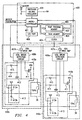
- FIGURE 4 is a partly schematic and partly block diagram of one electrical circuit formed in accordance with teachings of the present invention.
- this circuitry provides a pulsing bi-phasic current to transducer coils 104s and 104b at predetermined intervals, thereby activating the PEMF output signal according to a prescribed pre-programmed PEMF regimen. Except for transducer coils 104s and 104b, this circuitry may be physically located in control unit 50.
- the electrical circuitry includes both control circuitry 400, field sense circuitry 408 and drive circuitry 410, which all may be fabricated on a printed circuit board and encapsulated in control unit 50. In this embodiment, control circuitry 400 is operable to drive group circuitry 440s and 440b.
- Control circuitry 400 includes processor or microcontroller 401, with associated integrated circuit components: a program memory 402, a data memory 403, and Real Time Clock circuit 404.
- processor 401 may represent two individual microprocessors. One microprocessor may be used to control transducer coil 104s and the other microprocessor may be used to control transducer coil 104b.
- Processor 401 is in data communication with these associated components by means of a bus 405.
- a PEMF program can be loaded into a microcontroller EPROM or other memory and installed as PEMF program memory 402. Alternatively, the PEMF program can be read into the PEMF program memory via I/O port 406.
- Data memory 403 may be used to store data about the patient's use of bone mineral density stimulator 30, based on an internally maintained clock and calendar provided by clock circuit 404.
- PEMF program parameters--such as start time, stop time, duration, and daily average-- may be stored in data memory 403. This data can be read out or uploaded to any suitable printer, external device or communications link via the I/O port 406.
- I/O port 406 is a recessed Serial Input/Output (SIO) port for connecting to such an external device.
- SIO Serial Input/Output
- Processor 401 controls coil drive amplifier 407, which drives the energization and de-energization of transducer coils 104s and 104b.
- Field sensor or coil break detection circuits 408s and 408b sense the electromagnetic fields output by respective transducer coils 104s and 104b and provide a response signal to processor 401 for monitoring the operation of bone mineral density stimulator 30. This built-in monitoring circuitry will ensure that the treatment field is being generated by proper current flow in each transducer coil 104b and 104s.
- Processor 401 may store monitoring data in data memory 403, and will initiate a visible or audible warning signal or other alarm if the device is not generating the treatment field. If at any time during treatment either transducer 104b, 104s ceases to function properly, treatment will stop and the field fault indication is initiated.
- processor 401 receives power from a power source, such as a nine-volt lithium or alkaline battery, through a switching voltage regulator 409. Regulator 409 provides +5 volts power to processor 401 and its associated digital components.
- a power source such as a nine-volt lithium or alkaline battery
- Processor 401 and its associated components may be implemented with conventional integrated circuit devices.
- processor 401 may be a Motorola 68HC11 processor.
- the data memory 403 and clock circuit 404 may be a Dallas Semiconductor Corporation device.
- the PEMF program preferably outputs a pair of control signals, each comprising a series of pulse bursts.
- the two signals have their pulses offset, such that a pulse of one signal is high when a pulse of the other signal is low.
- These alternating control signals control the drive electronics so that it switches current on and off at the proper times to provide bi-phasic current for transducer coils 104s and 104b.
- a feature of the control signals is that at the beginning of one of the pulse bursts, its first pulse is shorter than the other pulses in the same pulse train.
- the first pulse train has pulses with 4 microseconds (4 ⁇ sec) on and 12 microseconds (12 ⁇ sec) off times, then the first pulse of the first pulse train is 2 microseconds (2 ⁇ sec).
- This first short pulse sets up the magnetic field for the PEMF stimulation therapy signal in the single-winding coil.
- energization of the magnetic field takes place to set the PEMF magnetic field away from zero.
- the next pulse on the other pulse train turns on for approximately twelve microseconds. This sets the current so that the drive flyback energy goes in a negative direction. This causes current to flow from an initial negative direction. The current then ramps up through zero and increases from a negative number through zero to a positive number during the pulse.
- Drive electronics 410s and 410b drive respective transducer coils 104s and 104b, so that transducer coils 104s and 104b then generate the desired PEMF stimulation therapy signals.
- Drive electronics 410s and 410b have a first transistor switch 411 between break detection circuit 408 and transducer coils 104s and 104b, and a second transistor switch 412 between energy recovery capacitance circuit 413 and transducer coils 104s and 104b. Switches 411 and 412 control the output signal from transducer coils 104s and 104b. In operation, each transducer coil 104s and 104b shapes the pulsed electromagnetic field pattern and recovers unused energy during the interpulse collapse of the generated field.
- switch 411 is turned on by coil drive amplifier 407 to present battery voltage across transducer coils 104s and 104b for a period of one-half a normal pulse duration of typically four microseconds (4 ⁇ sec). Activation current flows through transducer coils 104s and 104b to generate an output signal.
- switch 411 switches off, switch 412 switches on to charge energy recovery capacitance circuit 413 to a voltage equal to four times the battery voltage. This causes transducer coils 104s and 104b to discharge in the opposite direction during the off period of switch 411 as compared to the direction during its on period. Thus, energy recovery occurs without a secondary coil.
- Drive circuits 410s and 410b permit sequencing of the current through respective transducer coils 104s and 104b in both directions.
- the voltage V X4 may be derived using the flyback pulse from transducer coils 104s and 104b, instead of requiring a separate voltage boost circuit. By balancing the capacity of capacitors 413a and 413b, it is possible to eliminate the need for a separate four-times voltage supply circuit.
- energy recovery capacitance circuit 413 comprises two series connected capacitors 413a and 413b. Their capacitance ratio is at least 1:3, and in the example of this description is 1:10 (in microfarads).
- Various other capacitor configurations could be used for capacitance circuit 413, with the common characteristic that it provides the desired energy restoring voltage, here V X4 .
- energy recovery capacitance circuit 413 could comprise a capacitor and voltage regulator circuitry.
- Control circuitry 400 is also operable to drive additional group circuitry such as circuitry 440a and circuitry 440l (not explicitly shown). Such additional group circuitry may be placed in parallel with group circuitry 440s and 440b without substantively altering the load on control circuitry 400. Thus, a number of additional bone mineral density stimulator devices such as wrist and ankle transducer coils 104a and 104l may be releasably coupled to control circuitry 400, and operated in conjunction with transducer coils 104s and 104b. Such configurations are shown in FIGURES 1B and 1C.
- FIGURE 5 illustrates an example of an output waveform generated by transducer coils 104s and 104b.
- a pulse portion I is followed by pulse portion II.
- Pulse portion I has a duration of approximately four microseconds (4 ⁇ sec).
- Pulse portion II has a duration of approximately twelve microseconds (12 ⁇ sec).
- the voltage level for pulse portion I is approximately three times the voltage level for portion II.
- the output pulse periods (16 microseconds) and pulse frequency (62.5 kilohertz) of the output signal are in response to the pulsed drive signals.
- the output waveform is discussed in further detail in conjunction with FIGURES 8, 10A, 10B, and 10C.
- FIGURE 6 illustrates one embodiment of coil break detection circuit 408.
- a set/reset flip-flop 61 receives an upper input signal and a lower input signal. One of its Q outputs goes to flip-flop 62 and controls the operation of switch 412. The other Q output controls the operation of switch 411. The Q output from flip-flop 62 goes to flip-flop 63 as a clock signal.
- Switch 412 controls whether the COIL_LO signal goes to V x4 , while switch 411 shunts COIL_LO to ground.
- the COIL_HI signal provides supply voltage V.
- Resistor 64 and diode 65 receive supply voltage, V, from resistor 66.
- Flip-flop 63 receives as its D input the output from resister 66.
- the Q output from flip-flop 63 goes to NAND gate 67 to generate a sense output.
- the voltage V X4 is four times the voltage V, both being measured with respect to ground.
- the UPPER and LOWER signals consist of a burst of pulses, separated by an inter-burst period, as shown in FIGURE 7. These two signals are essentially non-overlapping ensuring the stable operation of the S/R flip-flop 61.
- the Q outputs of S/R flip-flop 61 are of opposite state and are also essentially non-overlapping, ensuring that switches 411 and 412 are never simultaneously on.
- both switches 411 and 412 are open.
- transducer coils 104s and 104b will pull the COIL_LO signal level to the supply voltage V. If a break should occur in the coil, the COIL_LO signal will be pulled to ground by resistor 64.
- Resistor 66, resistor 64, and diode 65 translate the COIL_LO signal to levels appropriate for the inputs of flip-flop 63 and NAND gate 67.
- the ratio of resistor 66 to resistor 64 is selected to provide a logic level "0" at the inputs of flip-flip 63 and NAND gate 67 should a break occur in transducer coils 104s and 104b.
- the output of flip-flop 62 is a single pulse occurring at the beginning of a burst, beginning with the first pulse of UPPER and terminating on the second pulse of UPPER.
- the rising edge of the output of flip-flop 62 occurs prior to the first rising edge of COIL_LO due to the relatively short time delay associated with flip-flop 62 versus switch 412 and switch 411.
- the pulse output of flip-flop 62 goes to flip-flop 63, samples the inter-burst voltage. If the inter-burst voltage is equal to V, the Q output of flip-flop 63 is a logic level "1" until the next sampling pulse, thereby enabling output of the inverse of the COIL_LO signal to processor 401 as the SENSE signal.
- the output of flip-flop 63 is set to a logic level "0", disabling the output of the inverse of the COIL_LO signal to processor 401.
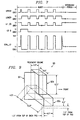
- FIGURE 7 illustrates the timing relationship of the logic signals that drive switches 411 and 412, as well as signals internal to coil break detection circuit 408.
- each logic burst signal there are a number of pulses, the duration of each upper pulse being only one-third the duration of lower pulse. Other parameters may also be used.
- FIGURE 8 is a table of parameters, requirements, units, and symbols that correspond to the timing diagram of FIGURE 7.
- the burst period is 26 milliseconds, during which a first pulse width is approximately two microseconds (2 ⁇ sec). Thereafter, the upper pulse width is approximately four microseconds (4 ⁇ sec). The lower pulse width is approximately twelve microseconds (12 ⁇ sec). The pulse period is approximately sixteen microseconds (16 ⁇ sec) for a pulse frequency of approximately 62.5 kilohertz. For the example of FIGURE 8, there are 1609 pulses per burst.
- Such a combination of parameters is particularly advantageous in increasing energy efficiency, since the area of each transducer 104s, 104b may be large. These parameters reduce the operating requirements for battery power.
- the invention may also use other timing parameters to achieve the desired PEMF signals and associated energy recovery operation.
- energy recovery capacitance circuit 413 provides an energy recovery voltage of four times the source voltage provided by the battery. As explained above, both the source voltage (V) and the energy recovery voltage (V 4X ) are lower than the voltages required for previous designs.
- FIGURE 9 is a schematic drawing showing an approximate treatment volume provided in the embodiment represented by bone mineral density stimulator 30 shown in FIGURE 1A.
- Treatment volume 90 includes first portion 90s and second portion 90b.
- First portion 90s and second portion 90b correspond to the treatment site targeted by the embodiment of bone mineral density stimulator 30 as shown in FIGURE 1A.
- Bone mineral density stimulator 30 preferably provides a uniform magnetic field and constant peak flux density throughout treatment volume 90.
- first portion 90s may have an approximate length of fifteen (15) inches, an approximate height of four and one half (4.5) inches, and an approximate depth of six (6) inches.
- second portion 90b may have an length versus width approximate width of fifteen and one-half (15.5) inches, an approximate height of four and one-half (4.5) inches, and an approximate depth of six (6) inches.
- Treatment volume 90 is measured at an approximate distance of one and one-half (1.5) inches from both first portion 36 and second portion 38 of pad 32.
- the length of first portion 90s extends approximately four and one-half (4.5) inches on either side of second portion 90b.
- This particular arrangement for first portion 90s and second portion 90b of treatment volume 90 is obtained as a result of the orientation, placement, and geometry of transducer coils 104s and 104b.
- the shape of treatment volume 90 depends on the particular arrangement, geometry, and orientation of transducer coils 104s and 104b.
- bone mineral density stimulator 30 It is particularly advantageous for a patient using bone mineral density stimulator 30 to be treated with a non-invasive uniform magnetic field and constant peak flux density throughout the volume of treatment site 90.
- the expected peak changes in flux density in this embodiment for bone mineral density stimulator 30 are discussed in conjunction with FIGURES 10B and 10C.
- bone mineral density stimulator 30 is operable to maintain a uniform magnetic field throughout treatment volume 90, as measured by magnetic field amplitude, intensity, and angle of divergence data as measured with respect to a plane perpendicular to the plane of symmetry, designated 92 in FIGURE 9.
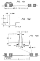
- FIGURES 10A, 10B, and 10C are drawings showing typical wave forms associated with bone mineral density stimulator 30.
- bone mineral density stimulator 30 delivers a burst of 1609 pulses during a burst period which are followed by an inter-burst period.
- Bone mineral density stimulator 30 delivers the burst at a rate of about one and a half pulse bursts per second, which corresponds to one burst approximately every 667 +/- 3 milliseconds (msec), as shown in FIGURE 10A.
- FIGURE 10B illustrates the peak changes in flux density during the upper pulse width and the lower pulse width as shown in and discussed in conjunction with FIGURE 5.
- the peak change in flux density during the upper pulse width is between four and eighteen T/s, also designated in units of dB/dt.
- the peak change in flux density is one and a half to six T/s.
- FIGURE 10C illustrates additional parameters associated with the wave form illustrated in FIGURE 5, and shows the relationship of that wave form to the pulse burst as shown in FIGURE 10A.
- each of the 1609 pulses as shown in FIGURE 10A as used in this embodiment is associated with typical values for the parameters detailed in Table III.
- the rise time, illustrated as t r in FIGURE 10C and the fall time, as designated t f in FIGURE 10C are both one microsecond (1 ⁇ sec). Both the rise time and the fall time are measured by the amount of time it takes for the wave form to rise or fall respectively from ten percent (10%) to ninety percent (90%) of the voltage level between pulse portions I and II as illustrated in FIGURE 5.
- Pulse portion I as illustrated in FIGURE 5 is designated t pw(+) , or on time, and lasts for four microseconds (4 ⁇ sec).
- Pulse portion II as illustrated in FIGURE 5 is designated t pw(-) , or off time, lasts for 12 microseconds (12 ⁇ sec).
- the peak flux density range in dB/dt for both pulse portion I and pulse portion II, is discussed previously in conjunction with FIGURE 10B is shown here with respect to the wave form as illustrated in FIGURE 10C.
Landscapes
- Health & Medical Sciences (AREA)
- Public Health (AREA)
- Engineering & Computer Science (AREA)
- Nuclear Medicine, Radiotherapy & Molecular Imaging (AREA)
- Radiology & Medical Imaging (AREA)
- Life Sciences & Earth Sciences (AREA)
- Animal Behavior & Ethology (AREA)
- Biomedical Technology (AREA)
- Veterinary Medicine (AREA)
- General Health & Medical Sciences (AREA)
- Magnetic Treatment Devices (AREA)
- Electrotherapy Devices (AREA)
- Medicines Containing Material From Animals Or Micro-Organisms (AREA)
- Pharmaceuticals Containing Other Organic And Inorganic Compounds (AREA)
- Surgical Instruments (AREA)
- Percussion Or Vibration Massage (AREA)
Claims (34)
- Eine Vorrichtung (30) zur Bereitstellung einer elektromagnetischen Therapie oder Stimulation der Knochenmineraldichte bei einem Patienten, die Folgendes umfasst:dadurch charakterisiert, dass der elektrische Stromkreis (400, 408, 410) einen Schaltkreis zur Wiedererlangung von Rücklaufenergie von den Wandlerspulen (104a, 104b) und zur Sequenzierung von Strom durch die Wandlerspulen (104a, 104b) in eine positive Richtung und eine negative Richtung umfasst.ein Polster (32), das einen ersten Teil (36) mit mindestens einer darin angeordneten Wandlerspule (104a) sowie einen zweiten Teil (38) mit mindestens einer darin angeordneten Wandlerspule (104b) ausweist:ein Gehäuse (50), das zum Anschluss an einem elektrischen Stromkreis (400,408,410) zur Erzeugung eines elektrischen Antriebssignals angepasst ist; sowieein Kabel (52a; 52b), das zur Verbindung des elektrischen Antriebssignals an der ersten Wandlerspule und der zweiten Wandlerspule zur Erzeugung jeweiliger elektromagnetischer Felder, die sich vom Polster aus ausdehnen, angepasst ist:
- Die Vorrichtung nach Anspruch 1, die weiterhin den ersten Teil (36) des Polsters (2) umfasst, welches eine allgemeine Konfiguration aufweist, die einem Stuhlsitz entspricht und die weiterhin den zweiten Teil (38) des Polsters (2) umfasst, welches eine allgemeine Konfiguration aufweist, die einer Stuhlrückenlehne entspricht.
- Die Vorrichtung nach Anspruch 1, wobei das besagte Polster (32) aus mindestens einer Materialschicht ausgebildet ist.
- Die Vorrichtung nach Anspruch 1, die weiterhin Folgendes umfasst:ein Extremitätenpolster (31), das einen Teil mit einer Konfiguration aufweist, welche allgemein an die obere Extremität eines Patienten anpassbar ist;mindestens eine dritte Wandlerspule (104a), die innerhalb des Extremitätenpolsters angeordnet ist;ein Kabel (52a), das zur Verbindung des elektrischen Antriebssignals mit der dritten Wandlerspule zur Erzeugung eines sich von dem Extremitätenpolster ausdehnenden elektromagnetischen Feldes angepasst ist.
- Die Vorrichtung nach Anspruch 1, die weiterhin Folgendes umfasst:ein Extremitätenpolster (35), das einen Teil mit einer Konfiguration aufweist, welche allgemein an die untere Extremität eines Patienten anpassbar ist; mindestens eine dritte Wandlerspule (104b), die innerhalb des Extremitätenpolsters angeordnet ist;ein Kabel (52b), das zur Verbindung des elektrischen Antriebssignals mit der dritten Wandlerspule zur Erzeugung eines sich von dem Extremitätenpolster ausdehnenden elektromagnetischen Feldes angepasst ist.
- Die Vorrichtung nach Anspruch 1, die weiterhin Folgendes umfasst:ein unteres Extremitätenpolster (35), das einen Teil mit einer Konfiguration aufweist, welche allgemein an die untere Extremität eines Patienten anpassbar ist;mindestens eine dritte Wandlerspule (104b), die innerhalb des unteren Extremitätenpolsters zur Erzeugung von elektromagnetischen Feldern als Reaktion auf das Antriebssignal angeordnet ist;ein oberes Extremitätenpolster (31), das einen Teil mit einer Konfiguration aufweist, welche allgemein an die obere Extremität eines Patienten anpassbar ist;mindestens eine vierte Wandlerspule (104a), die innerhalb des oberen Extremitätenpolsters zur Erzeugung von elektromagnetischen Feldern als Reaktion auf das Antriebssignal angeordnet ist;mindestens ein weiteres flexibles Kabel (51a, 52b), welches zur Verbindung des elektrischen Antriebssignals mit der dritten Wandlerspule und der vierten Wandlerspule angepasst ist.
- Eine Vorrichtung nach Anspruch 1, wobei der elektrische Stromkreis weiterhin mindestens einen zur Steuerung des Antriebssignals betreibbaren Prozessor umfasst.
- Die Vorrichtung nach Anspruch 1, die weiterhin eine Schnellkupplung (Quick-Disconnect) umfasst, die im flexiblen Kabel zwischen dem Gehäuse und den Wandlerspulen angeordnet ist.
- Die Vorrichtung nach Anspruch 1, wobei der elektrische Stromkreis weiterhin funktionsfähig ist zur Überwachung, ob die jeweiligen elektromagnetischen Felder von jeweils der ersten und zweiten Wandlerspule richtig erzeugt werden.
- Die Vorrichtung nach Anspruch 1, wobei der zweite Teil des Polsters weiterhin eine Materialschicht umfasst, welche anpassbar ist in Reaktion auf den Druck durch die allgemeine Form des Rückens des Patienten und welche bei Nachlassen des Drucks die allgemeine Form beibehält.
- Die Vorrichtung nach Anspruch 10, wobei weiterhin die zweite Wandlerspule eine ausreichende Flexibilität aufweist, dass sie sich an die allgemeine Form des Rückens des Patienten anpassen kann.
- Die Vorrichtung nach Anspruch 1, wobei das Gehäuse weiterhin eine Batterie zur Versorgung des elektrischen Stromkreises mit elektrischem Strom umfasst.
- Die Vorrichtung nach Anspruch 1 oder Anspruch 3, wobei das Polster weiterhin eine äußere Schicht aus einem Polyvinyl-Elastomer-Material und mindestens eine Schicht eines flexiblen Elastomerschaummaterials umfasst.
- Die Vorrichtung nach Anspruch 1 oder Anspruch 3, wobei das elektrische Anthebssignal und die erste und zweite Wandlerspule miteinander zusammenwirken, um ein gepulstes elektromagnetisches Feld zu erzeugen, welches eine Vielzahl von Pulsen innerhalb einer Pulsbreite von zehn Mikrosekunden bis zwanzig Mikrosekunden aufweist.
- Die Vorrichtung nach Anspruch 14, wobei die Vielzahl von Pulsen ungefähr eintausendsechshundertundneun (1609) beträgt.
- Die Vorrichtung nach Anspruch 3, die weiterhin dadurch gekennzeichnet ist, dass der erste Teil des Polsters flexibel mit dem zweiten Teil des Polsters verbunden ist.
- Die Vorrichtung nach Anspruch 3, die weiterhin mindestens einen Riemen (34) umfasst, der am zweiten Teil des Polsters zur freigebbaren Befestigung des Polsters an einer Stuhlrückenlehne angebracht ist.
- Die Vorrichtung nach Anspruch 3, wobei der zweite Teil (38) des Polsters weiterhin eine Schicht (40, 42, 44, 46, 48) eines Materials umfasst, welches in Reaktion auf den Druck durch die allgemeine Form des Rückens des Patienten anpassbar ist und welches die allgemeine Form beibehält, wenn eine Druckentlastung stattfindet.
- Die Vorrichtung nach Anspruch 18, wobei die Materialschicht eine Schicht umfasst, welche aus einem synthetischen harzartigen Material ausgebildet ist.
- Die Vorrichtung nach Anspruch 3, die zur Erzeugung einer Vielzahl von Pulsen angepasst ist, die eine Pulsbreite von ca. sechzehn Mikrosekunden aufweisen.
- Die Vorrichtung nach Anspruch 1, die so konfiguriert und angeordnet ist, dass bei der Verwendung die Durchführung einer elektromagnetischen Stimulation des Patienten ermöglicht wird, und zwar im Rahmen eines Behandlungsumfangs (90), welcher die proximalen Femura, Hüftgelenke, Lendenwirbelsäule und Brustwirbelsäule des Patienten umfasst.
- Die Vorrichtung nach Anspruch 1, die so konfiguriert und angeordnet ist, dass bei der Verwendung die Durchführung einer elektromagnetischen Stimulation der Person ermöglicht wird, und zwar im Rahmen eines Behandlungsumfangs (90), welcher das Bein und den Fußknöchel des Patienten umfasst.
- Die Vorrichtung nach Anspruch 1, die so konfiguriert und angeordnet ist, dass bei der Verwendung die Durchführung einer elektromagnetischen Stimulation des Patienten ermöglicht wird, und zwar im Rahmen eines Behandlungsumfangs (90), welcher den Arm und das Handgelenk des Patienten umfasst.
- Die Vorrichtung nach Anspruch 1, die so konfiguriert und angeordnet ist, dass bei der Verwendung die Durchführung einer elektromagnetischen Stimulation des Patienten ermöglicht wird, und zwar im Rahmen eines Behandlungsumfangs (90), welcher das Bein, den Fußknöchel, den Arm und das Handgelenk des Patienten umfasst.
- Die Vorrichtung nach Anspruch 1, die so konfiguriert und angeordnet ist, dass bei der Verwendung ein elektromagnetisches Feld erzeugt wird, welches den Patienten im Rahmen eines Behandlungsumfangs stimuliert, und wobei das von der Vorrichtung erzeugte elektromagnetische Feld ungefähr gleichförmig ist und die Peakflussdichte bei Verwendung ungefähr konstant innerhalb des Behandlungsumfangs ist.
- Die Vorrichtung nach Anspruch 1, die weiterhin Hilfsmittel (401, 403) zur Überwachung der Zeit umfasst, über die der Patient die elektromagnetische Stimulation empfangen hat.
- Eine Vorrichtung (30) zur Bereitstellung einer elektromagnetischen Therapie für einen Patienten, die Folgendes umfasst:dadurch gekennzeichnet, dass der elektrische Stromkreis einen Schaltkreis zur Wiedererlangung von Rücklaufenergie von den Wandlerspulen und zur Sequenzierung des Stroms durch die Wandlerspulen in eine positive Richtung und eine negative Richtung umfasst.ein Gehäuse (50), das einen elektrischen Stromkreis zur Erzeugung eines elektrischen Antriebssignals enthält;mindestens eine erste Wandlerspule, die in einem Sitzteil (22) eines Stuhls angeordnet ist, und mindestens eine zweite Wandlerspule, die innerhalb eines Rückenteils (24) des Stuhls angeordnet ist, zur Erzeugung entsprechender elektromagnetischer Felder in Reaktion auf das Antriebssignal; sowieein Kabel, das zur Verbindung des elektrischen Antriebssignals mit der ersten Wandlerspule und der zweiten Wandlerspule angepasst ist;
- Die Vorrichtung nach Anspruch 27, die weiterhin Folgendes umfasst:ein Extremitätenpolster (31), das ein Teil mit einer Konfiguration aufweist, welche allgemein an die obere Extremität eines Patienten anpassbar ist;mindestens eine dritte Wandlerspule, die innerhalb des Extremitätenpolsters zur Erzeugung von elektromagnetischen Feldern in Reaktion auf das Antriebssignal angeordnet ist; undein Kabel, welches zur Verbindung des elektrischen Antriebssignals mit der dritten Wandlerspule angepasst ist.
- Die Vorrichtung nach Anspruch 27, die weiterhin Folgendes umfasst:ein Extremitätenpolster (35), das einen Teil mit einer Konfiguration aufweist, welche allgemein an die untere Extremität eines Patienten anpassbar ist;mindestens eine dritte Wandlerspule, die innerhalb des Extremitätenpolsters zur Erzeugung von elektromagnetischen Feldern in Reaktion auf das Antriebssignal angeordnet ist; undein Kabel (54b), welches zur Verbindung der dritten wandlerspule am elektrischen Aatriebssignal angepasst ist.
- Die Vorrichtung nach Anspruch 27, die weiterhin Folgendes umfasst:mindestens eine dritte Wandlerspule, die innerhalb eines unteren Extremitäbenpoisters (35) angeordnet ist, und mindestens eine vierte Wandlerspule, die innerhalb eines oberen Extremitätenpolsters (31) zur Erzeugung von entsprechenden elektromagnetischen Feldern als Reaktion auf das Antriebssignal angeordnet ist; undmindestens ein weiteres Kabel, das zur Verbindung des elektrischen Antriebssignals mit der dritten Wandlerspule und der vierten Wandlerspule angepasst ist.
- Die Vorrichtung nach Anspruch 27, wobei weiterhin das Gehäuse innerhalb des Stuhls angeordnet ist.
- Die Vorrichtung nach Anspruch 27, wobei weiterhin das Gehäuse auf einem Tisch angeordnet ist.
- Die Vorrichtung nach Anspruch 27, wobei weiterhin das Kabel (54b) zur freigebbaren Verbindung an einer Steckdose (39) im Stuhl angepasst ist.
- Die Vorrichtung nach Anspruch 27, die weiterhin dadurch gekennzeichnet ist, dass der Stahl durch Betätigung zurücklehnbar ist.
Applications Claiming Priority (3)
| Application Number | Priority Date | Filing Date | Title |
|---|---|---|---|
| US9518598P | 1998-08-03 | 1998-08-03 | |
| US95185P | 1998-08-03 | ||
| PCT/US1999/017221 WO2000007665A1 (en) | 1998-08-03 | 1999-07-30 | Pemf treatment for osteoporosis and tissue growth stimulation |
Publications (2)
| Publication Number | Publication Date |
|---|---|
| EP1100582A1 EP1100582A1 (de) | 2001-05-23 |
| EP1100582B1 true EP1100582B1 (de) | 2005-06-15 |
Family
ID=22250543
Family Applications (1)
| Application Number | Title | Priority Date | Filing Date |
|---|---|---|---|
| EP99937623A Expired - Lifetime EP1100582B1 (de) | 1998-08-03 | 1999-07-30 | Pemf-vorrichtung zur behandlung der osteoporose und zur stimulation des wachstums von geweben |
Country Status (9)
| Country | Link |
|---|---|
| US (2) | US6418345B1 (de) |
| EP (1) | EP1100582B1 (de) |
| JP (1) | JP2002522125A (de) |
| AT (1) | ATE297786T1 (de) |
| AU (1) | AU5241699A (de) |
| CA (1) | CA2339285C (de) |
| DE (1) | DE69925839T2 (de) |
| ES (1) | ES2245113T3 (de) |
| WO (1) | WO2000007665A1 (de) |
Families Citing this family (135)
| Publication number | Priority date | Publication date | Assignee | Title |
|---|---|---|---|---|
| US6463336B1 (en) * | 1999-04-01 | 2002-10-08 | Mmtc, Inc | Active bandage suitable for applying pulsed radio-frequencies or microwaves to the skin for medical purposes |
| US6616595B2 (en) * | 2000-09-01 | 2003-09-09 | George Riach, Jr. | Vortex magnetic regenerating device |
| PL342829A1 (en) * | 2000-09-26 | 2002-04-08 | Janusz Wodnicki | Bioenergetical therapeutic device |
| US7160241B1 (en) * | 2000-10-06 | 2007-01-09 | Ewa Herbst | Treatment of living tissues using electromagnetic fields |
| DE10109429A1 (de) * | 2001-02-27 | 2002-09-12 | Sabine Hess | Therapeutisches Sitz- und/oder Liegemöbel |
| ES2206025B1 (es) * | 2002-05-21 | 2005-07-16 | Antonio Madroñero De La Cal | Dispositivo de campos magneticos multiples para su utilizacion en magnetoterapia y magneto acupuntura. |
| CA2454749A1 (en) * | 2002-12-31 | 2004-06-30 | Glen A. Gordon | Method and apparatus for pulsed electromagnetic therapy |
| JP2004284497A (ja) * | 2003-03-24 | 2004-10-14 | Autech Japan Inc | 配索構造 |
| GB2400316A (en) * | 2003-04-10 | 2004-10-13 | Richard Markoll | Electromagnetic stimulation in patients with osteoporosis |
| MXPA06005358A (es) * | 2003-11-14 | 2006-07-10 | Univ Pennsylvania | Metodo y aparato para el tratamiento de la osteoartritis, enfermedades de los cartilagos, defectos y lesiones en la cadena humana. |
| US10350428B2 (en) | 2014-11-04 | 2019-07-16 | Endonovo Therapetics, Inc. | Method and apparatus for electromagnetic treatment of living systems |
| US9415233B2 (en) | 2003-12-05 | 2016-08-16 | Rio Grande Neurosciences, Inc. | Apparatus and method for electromagnetic treatment of neurological pain |
| US9440089B2 (en) | 2003-12-05 | 2016-09-13 | Rio Grande Neurosciences, Inc. | Apparatus and method for electromagnetic treatment of neurological injury or condition caused by a stroke |
| US9433797B2 (en) | 2003-12-05 | 2016-09-06 | Rio Grande Neurosciences, Inc. | Apparatus and method for electromagnetic treatment of neurodegenerative conditions |
| US9427598B2 (en) | 2010-10-01 | 2016-08-30 | Rio Grande Neurosciences, Inc. | Method and apparatus for electromagnetic treatment of head, cerebral and neural injury in animals and humans |
| US20130218235A9 (en) * | 2005-03-07 | 2013-08-22 | Arthur A. Pilla | Excessive fibrous capsule formation and capsular contracture apparatus and method for using same |
| US9656096B2 (en) | 2003-12-05 | 2017-05-23 | Rio Grande Neurosciences, Inc. | Method and apparatus for electromagnetic enhancement of biochemical signaling pathways for therapeutics and prophylaxis in plants, animals and humans |
| US20110112352A1 (en) * | 2003-12-05 | 2011-05-12 | Pilla Arthur A | Apparatus and method for electromagnetic treatment |
| US8961385B2 (en) | 2003-12-05 | 2015-02-24 | Ivivi Health Sciences, Llc | Devices and method for treatment of degenerative joint diseases with electromagnetic fields |
| US7744524B2 (en) * | 2003-12-05 | 2010-06-29 | Ivivi Health Sciences, Llc | Apparatus and method for electromagnetic treatment of plant, animal, and human tissue, organs, cells, and molecules |
| US7651459B2 (en) * | 2004-01-06 | 2010-01-26 | Neuronetics, Inc. | Method and apparatus for coil positioning for TMS studies |
| JP2007531562A (ja) | 2004-02-12 | 2007-11-08 | エヌディーアイ メディカル, エルエルシー | 機能的または治療的神経筋刺激を提供するための携帯式アセンブリ、システムおよび方法 |
| US8177702B2 (en) | 2004-04-15 | 2012-05-15 | Neuronetics, Inc. | Method and apparatus for determining the proximity of a TMS coil to a subject's head |
| NZ551316A (en) | 2004-04-19 | 2008-03-28 | Ivivi Technologies Inc | Electromagnetic treatment apparatus and method |
| WO2005117696A2 (en) * | 2004-05-27 | 2005-12-15 | Parker Richard F | Method and apparatus for generating a therapeutic magnetic field |
| US20060030896A1 (en) * | 2004-07-09 | 2006-02-09 | Simon Bruce J | Pulsed electromagnetic field method of treatment of degenerative disc disease |
| US8088058B2 (en) * | 2005-01-20 | 2012-01-03 | Neuronetics, Inc. | Articulating arm |
| US20060200212A1 (en) * | 2005-02-17 | 2006-09-07 | Brawn Peter R | Light therapy device for treatment of bone disorders and biostimulation of bone and soft tissue |
| US20070248930A1 (en) | 2005-02-17 | 2007-10-25 | Biolux Research Ltd. | Light therapy apparatus and methods |
| EP1723985B1 (de) * | 2005-05-19 | 2008-03-12 | Medithera Medizinische Systeme AG | Magnetfeldtherapiegerät zum Erzeugen eines zeitlich veränderlichen elektromagnetischen Feldes mittels einer Folge von Stromimpulsen |
| US7465269B2 (en) * | 2005-07-14 | 2008-12-16 | Djo, Llc | Bone growth stimulator |
| US7824324B2 (en) * | 2005-07-27 | 2010-11-02 | Neuronetics, Inc. | Magnetic core for medical procedures |
| CN101299958B (zh) * | 2005-09-29 | 2011-03-23 | 康曼德公司 | 传感器支架 |
| US20070149901A1 (en) * | 2005-12-08 | 2007-06-28 | Em-Probe, Inc. | Methods and apparatus for pulsed electromagnetic therapy |
| US8147395B2 (en) | 2006-11-28 | 2012-04-03 | Gregory S. Anderson | Bone-activity stimulation apparatus and method |
| US8439816B2 (en) * | 2009-07-14 | 2013-05-14 | Pulse, Llc | Piezoelectric, micro-exercise apparatus and method |
| DE102007003361A1 (de) * | 2007-01-17 | 2008-07-31 | Patex Group Ltd. | Vibrationstherapievorrichtung |
| WO2008109058A1 (en) * | 2007-03-01 | 2008-09-12 | Finsterwald P Michael | Magnetic stimulator |
| US9968797B2 (en) | 2007-05-03 | 2018-05-15 | Orthocor Medical, Inc. | Electromagnetic thermal therapy |
| US8768454B2 (en) * | 2007-05-03 | 2014-07-01 | Orthocor Medical, Inc. | Electromagnetic thermal therapy |
| US7783348B2 (en) * | 2007-05-03 | 2010-08-24 | Orthocor Medical, Inc. | Stimulation device for treating osteoarthritis |
| US9884200B2 (en) * | 2008-03-10 | 2018-02-06 | Neuronetics, Inc. | Apparatus for coil positioning for TMS studies |
| JP4719756B2 (ja) * | 2008-03-12 | 2011-07-06 | ファミリー株式会社 | マッサージ機 |
| JP5676445B2 (ja) | 2008-08-01 | 2015-02-25 | エヌディーアイ メディカル, エルエルシー | 機能的または治療的な神経刺激を提供する携帯型アセンブリ、システムおよび方法 |
| US9457198B2 (en) * | 2009-02-18 | 2016-10-04 | Shenzhen Cornley Hi-Tech Co., Ltd. | Ultra-low frequency magnetic stimulating device and operational method thereof |
| US8939913B2 (en) | 2009-02-27 | 2015-01-27 | Thermimage, Inc. | Monitoring system |
| US8939914B2 (en) | 2009-02-27 | 2015-01-27 | Thermimage, Inc. | Radiometers and related devices and methods |
| US9844333B2 (en) * | 2009-03-24 | 2017-12-19 | International Business Machines Corporation | Remote delivery and monitoring of health care |
| US11191975B2 (en) | 2009-07-14 | 2021-12-07 | Pulse, Llc | Micro-coil wristband |
| US11878181B2 (en) | 2009-07-14 | 2024-01-23 | Pulse, Llc | Micro-coil wristband |
| US9498639B2 (en) | 2014-05-13 | 2016-11-22 | Pulse, Llc | Immersive, flux-guided, micro-coil apparatus and method |
| US10507333B2 (en) | 2009-07-14 | 2019-12-17 | Pulse, Llc | Immersive, flux-guided, micro-coil apparatus and method |
| US8460167B2 (en) * | 2009-09-14 | 2013-06-11 | Minnesota Medical Physics Llc | Thermally assisted pulsed electro-magnetic field stimulation device and method for treatment of osteoarthritis |
| US8827886B2 (en) | 2009-09-14 | 2014-09-09 | Minnesota Medical Physics Llc | Thermally assisted pulsed electro-magnetic field stimulation device and method for treatment of osteoarthritis |
| US8932196B2 (en) | 2009-09-14 | 2015-01-13 | Minnesota Medical Physics Llc | Thermally assisted pulsed electro-magnetic field stimulation device and method for treatment of osteoarthritis |
| US20110077727A1 (en) * | 2009-09-28 | 2011-03-31 | Clyde Norman Shealy | DNA Telomere Rejuvenation |
| US8137259B1 (en) | 2009-12-01 | 2012-03-20 | Magnafix, Llc | Magnetic method for treatment of an animal |
| US8376925B1 (en) * | 2009-12-01 | 2013-02-19 | Robert Glenn Dennis | Magnetic system for treatment of a tissue |
| US8029432B2 (en) * | 2009-12-01 | 2011-10-04 | Magnafix, Llc | Magnetic system for treatment of cellular dysfunction of a tissue or an extracellular matrix disruption of a tissue |
| EP2627283B1 (de) | 2010-10-13 | 2015-09-23 | Biolux Research Limited | Vorrichtung zur zahnregulierung mithilfe schwerer kräfte |
| EP2648651B1 (de) | 2010-12-08 | 2016-11-23 | Biolux Research Limited | Vorrichtungen zur regulation einer knochenneumodellierung oder einer zahnbewegung durch lichttherapie und funktionsanwendung dafür |
| WO2013091585A1 (en) | 2011-12-21 | 2013-06-27 | Enjoy Spol. S R.O. | Seat with anti-cellulitis effects |
| US8343027B1 (en) | 2012-01-30 | 2013-01-01 | Ivivi Health Sciences, Llc | Methods and devices for providing electromagnetic treatment in the presence of a metal-containing implant |
| JP5009445B2 (ja) * | 2012-03-19 | 2012-08-22 | ファミリー株式会社 | マッサージ機 |
| JP5220933B2 (ja) * | 2012-04-04 | 2013-06-26 | ファミリー株式会社 | マッサージ機 |
| US20130280671A1 (en) | 2012-04-19 | 2013-10-24 | Biolux Research Ltd. | Intra-oral light therapy apparatuses and methods for their use |
| US20130317280A1 (en) * | 2012-05-22 | 2013-11-28 | Biotest Medical Corporation | Magnetic field generating seat cushion |
| DE102012013534B3 (de) | 2012-07-05 | 2013-09-19 | Tobias Sokolowski | Vorrichtung für repetitive Nervenstimulation zum Abbau von Fettgewebe mittels induktiver Magnetfelder |
| JP5873053B2 (ja) * | 2013-09-19 | 2016-03-01 | ファミリーイナダ株式会社 | マッサージ機 |
| CN111330163A (zh) | 2013-10-22 | 2020-06-26 | 碧乐生物光子科研控股有限公司 | 口腔内光疗法装置以及使用它们的方法 |
| US9801905B2 (en) | 2014-03-13 | 2017-10-31 | Hossam Abdel Salam El Sayed Mohamed | Use of organic sulphur, antioxidants, and amino acids in conjunction with exercise and electromagnetic stimulation to treat osteoporosis |
| GB201406604D0 (en) * | 2014-04-11 | 2014-05-28 | Zeez Technology Ltd | Therapeutic field generator |
| EP3131628A4 (de) | 2014-04-16 | 2017-11-22 | Ivivi Health Sciences, LLC | Zweiteiliger pulsierender elektromagnetischer feldapplikator zur anwendung von therapeutischer energie |
| USD763453S1 (en) | 2014-05-13 | 2016-08-09 | Pulse, Llc | Micro-coil array |
| USD762864S1 (en) | 2014-05-13 | 2016-08-02 | Pulse, Llc | Micro-coil array |
| CN104287506A (zh) * | 2014-10-16 | 2015-01-21 | 王春雷 | 带有电磁场的椅子 |
| US11491342B2 (en) | 2015-07-01 | 2022-11-08 | Btl Medical Solutions A.S. | Magnetic stimulation methods and devices for therapeutic treatments |
| US10124187B2 (en) | 2015-04-28 | 2018-11-13 | Btl Holdings Limited | Combination of radiofrequency and magnetic treatment methods |
| US9937358B2 (en) | 2015-07-01 | 2018-04-10 | Btl Holdings Limited | Aesthetic methods of biological structure treatment by magnetic field |
| US10695575B1 (en) | 2016-05-10 | 2020-06-30 | Btl Medical Technologies S.R.O. | Aesthetic method of biological structure treatment by magnetic field |
| US10549110B1 (en) | 2015-07-01 | 2020-02-04 | Btl Medical Technologies S.R.O. | Aesthetic method of biological structure treatment by magnetic field |
| US10821295B1 (en) | 2015-07-01 | 2020-11-03 | Btl Medical Technologies S.R.O. | Aesthetic method of biological structure treatment by magnetic field |
| US10549109B2 (en) | 2015-07-01 | 2020-02-04 | Btl Medical Technologies S.R.O. | Aesthetic method of biological structure treatment by magnetic field |
| US10245439B1 (en) * | 2015-07-01 | 2019-04-02 | Medical Technologies Cz A.S. | Aesthetic method of biological structure treatment by magnetic field |
| US10569095B1 (en) | 2015-07-01 | 2020-02-25 | Btl Medical Technologies S.R.O. | Aesthetic method of biological structure treatment by magnetic field |
| US20180001107A1 (en) | 2016-07-01 | 2018-01-04 | Btl Holdings Limited | Aesthetic method of biological structure treatment by magnetic field |
| US10471269B1 (en) | 2015-07-01 | 2019-11-12 | Btl Medical Technologies S.R.O. | Aesthetic method of biological structure treatment by magnetic field |
| US10478633B2 (en) | 2015-07-01 | 2019-11-19 | Btl Medical Technologies S.R.O. | Aesthetic method of biological structure treatment by magnetic field |
| US10569094B2 (en) | 2015-07-01 | 2020-02-25 | Btl Medical Technologies S.R.O. | Aesthetic method of biological structure treatment by magnetic field |
| US10493293B2 (en) | 2015-07-01 | 2019-12-03 | Btl Medical Technologies S.R.O. | Aesthetic method of biological structure treatment by magnetic field |
| US11266850B2 (en) | 2015-07-01 | 2022-03-08 | Btl Healthcare Technologies A.S. | High power time varying magnetic field therapy |
| US10709894B2 (en) | 2015-07-01 | 2020-07-14 | Btl Medical Technologies S.R.O. | Aesthetic method of biological structure treatment by magnetic field |
| US9974519B1 (en) | 2015-07-01 | 2018-05-22 | Btl Holdings Limited | Aesthetic method of biologoical structure treatment by magnetic field |
| US10478634B2 (en) | 2015-07-01 | 2019-11-19 | Btl Medical Technologies S.R.O. | Aesthetic method of biological structure treatment by magnetic field |
| US10695576B2 (en) | 2015-07-01 | 2020-06-30 | Btl Medical Technologies S.R.O. | Aesthetic method of biological structure treatment by magnetic field |
| US11253717B2 (en) | 2015-10-29 | 2022-02-22 | Btl Healthcare Technologies A.S. | Aesthetic method of biological structure treatment by magnetic field |
| US10398906B2 (en) * | 2016-03-10 | 2019-09-03 | Kosivana Holdings Limited | Systems and methods for pain treatment using spinal nerve magnetic stimulation |
| US10661094B2 (en) * | 2016-04-18 | 2020-05-26 | Wave Neuroscience, Inc. | Systems and methods for spasticity treatment using spinal nerve magnetic stimulation |
| US11464993B2 (en) | 2016-05-03 | 2022-10-11 | Btl Healthcare Technologies A.S. | Device including RF source of energy and vacuum system |
| US11247039B2 (en) | 2016-05-03 | 2022-02-15 | Btl Healthcare Technologies A.S. | Device including RF source of energy and vacuum system |
| US10709895B2 (en) | 2016-05-10 | 2020-07-14 | Btl Medical Technologies S.R.O. | Aesthetic method of biological structure treatment by magnetic field |
| US11534619B2 (en) | 2016-05-10 | 2022-12-27 | Btl Medical Solutions A.S. | Aesthetic method of biological structure treatment by magnetic field |
| US10583287B2 (en) | 2016-05-23 | 2020-03-10 | Btl Medical Technologies S.R.O. | Systems and methods for tissue treatment |
| US10556122B1 (en) | 2016-07-01 | 2020-02-11 | Btl Medical Technologies S.R.O. | Aesthetic method of biological structure treatment by magnetic field |
| US11141219B1 (en) | 2016-08-16 | 2021-10-12 | BTL Healthcare Technologies, a.s. | Self-operating belt |
| IT201600093158A1 (it) * | 2016-09-15 | 2018-03-15 | Amel Medical Div S R L | Struttura di supporto per il corpo umano per magnetoterapia e seduta comprendente tale struttura |
| WO2018089795A1 (en) | 2016-11-10 | 2018-05-17 | Qoravita LLC | System and method for applying a low frequency magnetic field to biological tissues |
| US10039929B1 (en) | 2017-04-04 | 2018-08-07 | BLT Holdings Limited | Method and device for pelvic floor tissue treatment |
| US11896823B2 (en) | 2017-04-04 | 2024-02-13 | Btl Healthcare Technologies A.S. | Method and device for pelvic floor tissue treatment |
| US20180318579A1 (en) | 2017-05-06 | 2018-11-08 | Smartimplantsystems, Inc. | Active implantable medical device associated with, or integrated into, an orthopedic implant device |
| US10363846B2 (en) * | 2017-05-30 | 2019-07-30 | Lear Corporation | Vehicle seating system having seat with individually controllable electromagnetic coils |
| CN107198549A (zh) * | 2017-07-05 | 2017-09-26 | 山东中医药大学 | 一种电磁式冲击波骨科治疗装置 |
| US11850440B2 (en) * | 2019-08-22 | 2023-12-26 | University Of Iowa Research Foundation | Therapeutic systems using magnetic fields |
| US12424305B2 (en) | 2018-02-20 | 2025-09-23 | University Of Iowa Research Foundation | Closed-loop AI-optimized EMF treatment and digital delivery of data |
| US11666775B2 (en) * | 2018-03-29 | 2023-06-06 | Minnesota Medical Physics Llc | Method and apparatus for treatment of benign prostatic hyperplasia (BPH) |
| US11534246B2 (en) * | 2018-06-15 | 2022-12-27 | Verb Surgical Inc. | User input device for use in robotic surgery |
| CO2018007468A1 (es) | 2018-07-16 | 2020-01-17 | Panacea Quantum Leap Tech Llc | Método de estimulación de tejidos con campos electromagnéticos que generan jerk |
| JP7151356B2 (ja) | 2018-10-09 | 2022-10-12 | スミダコーポレーション株式会社 | 電気刺激装置 |
| DE102019103462B3 (de) | 2019-02-12 | 2020-06-18 | Dr. Simon Consulting Gmbh | Therapiegerät zur gepulsten magnetischen Induktion |
| PL4417249T3 (pl) | 2019-04-11 | 2026-04-20 | Btl Medical Solutions A.S. | Urządzenia do zabiegów na strukturach biologicznych za pomocą częstotliwości radiowej |
| US12156689B2 (en) | 2019-04-11 | 2024-12-03 | Btl Medical Solutions A.S. | Methods and devices for aesthetic treatment of biological structures by radiofrequency and magnetic energy |
| US12558146B2 (en) | 2019-04-11 | 2026-02-24 | Btl Medical Solutions A.S. | Methods and devices for aesthetic treatment of biological structures by radiofrequency and magnetic energy |
| US11020603B2 (en) | 2019-05-06 | 2021-06-01 | Kamran Ansari | Systems and methods of modulating electrical impulses in an animal brain using arrays of planar coils configured to generate pulsed electromagnetic fields and integrated into clothing |
| CN114502237A (zh) | 2019-05-06 | 2022-05-13 | 卡姆兰·安萨里 | 配置为生成脉冲电磁场并集成到衣物中的平面线圈治疗阵列 |
| DE102019121072A1 (de) * | 2019-08-05 | 2021-02-11 | Prof. Dr. Fischer AG | Vorrichtung zur Magnetfeldstimulation von Körpergewebe eines Benutzers zur Verwendung in der digitalen Telemedizin |
| US12582830B2 (en) * | 2019-08-23 | 2026-03-24 | United States Government As Represented By The Department Of Veterans Affairs | Devices, systems and methods for treating back pain with EMS |
| US11878167B2 (en) | 2020-05-04 | 2024-01-23 | Btl Healthcare Technologies A.S. | Device and method for unattended treatment of a patient |
| US12611545B2 (en) | 2020-05-04 | 2026-04-28 | Btl Healthcare Technologies A.S. | Device and method for unattended treatment of a patient |
| ES2993637T3 (en) | 2020-05-04 | 2025-01-03 | Btl Healthcare Technologies As | Device for unattended treatment of a patient |
| KR102240304B1 (ko) * | 2020-09-10 | 2021-04-13 | 주식회사 엠엔 | 의자 장착용 성장판 자극 장치 및 그 장치의 구동방법 |
| KR102506170B1 (ko) * | 2020-09-24 | 2023-03-06 | 주식회사 리메드 | 자기장 인가 장치 |
| US20220118269A1 (en) * | 2020-10-16 | 2022-04-21 | University Of Iowa Research Foundation | Monitoring efficacy of magnetic and electric fields using biomarkers |
| CA3260012A1 (en) | 2021-10-13 | 2023-04-20 | Btl Medical Solutions A.S. | AESTHETIC TREATMENT DEVICES FOR BIOLOGICAL STRUCTURES USING RADIOFREQUENCY AND MAGNETIC ENERGY |
| US11896816B2 (en) | 2021-11-03 | 2024-02-13 | Btl Healthcare Technologies A.S. | Device and method for unattended treatment of a patient |
| US20260097227A1 (en) | 2024-10-08 | 2026-04-09 | Btl Medical Solutions A.S. | Devices and methods for application of a magnetic field to the nervous system |
Family Cites Families (31)
| Publication number | Priority date | Publication date | Assignee | Title |
|---|---|---|---|---|
| US4266532A (en) | 1976-11-17 | 1981-05-12 | Electro-Biology, Inc. | Modification of the growth, repair and maintenance behavior of living tissues and cells by a specific and selective change in electrical environment |
| US4456001A (en) | 1982-07-02 | 1984-06-26 | Electro-Biology, Inc. | Apparatus for equine hoof treatment |
| US4635643A (en) | 1982-09-28 | 1987-01-13 | The Medical College Of Wisconsin Research Foundation, Inc. | Assay method for the in vivo quantitative determination of mineral content in bone |
| US4501265A (en) | 1982-12-23 | 1985-02-26 | Electro-Biology, Inc. | Applicator head for electromagnetic treatment of an afflicted body region |
| US4550714A (en) | 1983-03-09 | 1985-11-05 | Electro-Biology, Inc. | Electromagnetic coil insert for an orthopedic cast or the like |
| US5058582A (en) | 1983-06-29 | 1991-10-22 | Sheldon Thaler | Apparatus for reactively applying electrical energy pulses to a living body |
| US4911686A (en) | 1983-06-29 | 1990-03-27 | Sheldon Thaler | Apparatus for reactively applying electrical energy pulses to a living body |
| US4654574A (en) | 1983-06-29 | 1987-03-31 | Sheldon Thaler | Apparatus for reactively applying electrical energy pulses to a living body |
| WO1985000293A1 (en) * | 1983-07-13 | 1985-01-31 | Electro-Biology, Inc. | Modification of the growth, repair and maintenance behavior of living tissues and cells by a specific and selective change in electrical environment |
| CA1192261A (en) | 1984-02-29 | 1985-08-20 | David J. Stewart | Magnetic biological device |
| US4548208A (en) | 1984-06-27 | 1985-10-22 | Medtronic, Inc. | Automatic adjusting induction coil treatment device |
| US4662378A (en) | 1984-10-30 | 1987-05-05 | Wendl Thomis | Device for monitoring body signals |
| US4616629A (en) | 1985-05-24 | 1986-10-14 | Electro-Biology, Inc. | Coil construction for electromagnetic treatment of an afflicted body region |
| US4932951A (en) | 1988-03-23 | 1990-06-12 | Life Resonances, Inc. | Method and apparatus for controlling tissue growth and an applied fluctuating magnetic field |
| US5088976A (en) | 1988-03-23 | 1992-02-18 | Life Resonances, Inc. | Deformable magnetic field aiding coils for use in controlling tissue growth |
| US5318561A (en) | 1988-03-23 | 1994-06-07 | Life Resonances Inc. | Deformable magnetic field aiding coils for use in controlling tissue growth |
| US4974114A (en) | 1989-02-13 | 1990-11-27 | Lti Biomedical, Inc. | Energy recovery circuit for electrotherapy device |
| US5084003A (en) * | 1989-11-24 | 1992-01-28 | Dragan Susic | Magnetic massage therapy device |
| IE62090B1 (en) | 1990-03-29 | 1994-12-14 | Foley Nolan Darragh | Electromagnetic apparatus for use in therapy |
| US5066272A (en) | 1990-06-29 | 1991-11-19 | The Johns Hopkins University | Magnetic nerve stimulator |
| US5181902A (en) | 1990-09-21 | 1993-01-26 | American Medical Electronics, Inc. | Double-transducer system for PEMF Therapy |
| US5269747A (en) | 1990-09-21 | 1993-12-14 | American Medical Electronics, Inc. | Double-transducer system for PEMF therapy |
| US5195941A (en) | 1991-01-07 | 1993-03-23 | American Medical Electronics, Inc. | Contoured triangular transducer system for PEMF therapy |
| US5314401A (en) | 1991-03-29 | 1994-05-24 | Amei Technologies Inc. | Conformable PEMF transducer |
| US5195940A (en) * | 1991-06-20 | 1993-03-23 | Iatromed, Inc. | Method for increased production of growth factor in living tissue using an applied fluctuating magnetic field |
| US5478303A (en) | 1992-09-18 | 1995-12-26 | Foley-Nolan; Darragh | Electromagnetic apparatus for use in therapy |
| US5338286A (en) | 1992-12-08 | 1994-08-16 | Electro-Biology, Inc. | Electromagnetic bioresponse by selective spectral suppression in pulsed field stimulation |
| DE9300499U1 (de) * | 1993-01-21 | 1993-03-25 | Ralf Schrank Magnetfeldtechnik, 7770 Überlingen | Sitzmöbel zur Anwendung in der Magnetfeld-Therapie |
| DE69725484T2 (de) * | 1996-02-15 | 2004-07-15 | Nihon Kohden Corp. | Vorrichtung zur Behandlung von Harninkontinenz |
| US5743844A (en) | 1996-11-01 | 1998-04-28 | Amei Technologies, Inc. | High efficiency pulsed electromagnetic field (PEMF) stimulation therapy method and system |
| US6179769B1 (en) * | 1996-12-27 | 2001-01-30 | Nihon Kohden Corporation | Magnetic stimulus type urinary incontinence treatment apparatus |
-
1999
- 1999-07-30 EP EP99937623A patent/EP1100582B1/de not_active Expired - Lifetime
- 1999-07-30 AU AU52416/99A patent/AU5241699A/en not_active Abandoned
- 1999-07-30 WO PCT/US1999/017221 patent/WO2000007665A1/en not_active Ceased
- 1999-07-30 DE DE69925839T patent/DE69925839T2/de not_active Expired - Lifetime
- 1999-07-30 AT AT99937623T patent/ATE297786T1/de active
- 1999-07-30 CA CA002339285A patent/CA2339285C/en not_active Expired - Lifetime
- 1999-07-30 ES ES99937623T patent/ES2245113T3/es not_active Expired - Lifetime
- 1999-07-30 US US09/365,157 patent/US6418345B1/en not_active Expired - Fee Related
- 1999-07-30 JP JP2000563346A patent/JP2002522125A/ja active Pending
-
2002
- 2002-04-29 US US10/135,662 patent/US6839595B2/en not_active Expired - Lifetime
Also Published As
| Publication number | Publication date |
|---|---|
| US20020165583A1 (en) | 2002-11-07 |
| DE69925839T2 (de) | 2006-05-11 |
| WO2000007665A1 (en) | 2000-02-17 |
| CA2339285A1 (en) | 2000-02-17 |
| US6839595B2 (en) | 2005-01-04 |
| US6418345B1 (en) | 2002-07-09 |
| ATE297786T1 (de) | 2005-07-15 |
| JP2002522125A (ja) | 2002-07-23 |
| DE69925839D1 (de) | 2005-07-21 |
| ES2245113T3 (es) | 2005-12-16 |
| AU5241699A (en) | 2000-02-28 |
| EP1100582A1 (de) | 2001-05-23 |
| CA2339285C (en) | 2009-03-10 |
Similar Documents
| Publication | Publication Date | Title |
|---|---|---|
| US6418345B1 (en) | PEMF stimulator for treating osteoporosis and stimulating tissue growth | |
| US6678562B1 (en) | Combined tissue/bone growth stimulator and external fixation device | |
| EP3740275B1 (de) | Externes elektronisches pflaster zur beschleunigung der knochenheilung oder regeneration nach einem trauma | |
| US6024691A (en) | Cervical collar with integrated electrical circuitry for electromagnetic field therapy | |
| US7740574B2 (en) | Electromagnetic treatment induction apparatus and method for using same | |
| EP3253443B1 (de) | Vorrichtung zur behandlung von schnarchen und schlafapnoe | |
| EP0641230B1 (de) | Elektrische stimulierung zur behandlung von inkontinenz und anderen neuromuskularerkrankungen | |
| US5974342A (en) | Electrical stimulation therapy method and apparatus | |
| US20090326611A1 (en) | Method of Powering Implanted Devices by Direct Transfer of Electrical Energy | |
| CN1956749B (zh) | 电疗设备 | |
| US7758490B2 (en) | Integrated coil apparatus for therapeutically treating human and animal cells, tissues and organs with electromagnetic fields and method for using same | |
| US7175587B2 (en) | Method and apparatus for pulsed electromagnetic therapy | |
| US6132362A (en) | Pulsed electromagnetic field (PEMF) stimulation therapy system with bi-phasic coil | |
| EP0977615B1 (de) | Gerät zur verabreichung von mikrostrom elektrotherapie | |
| US20090216294A1 (en) | Self-contained electronic musculoskeletal stimulation apparatus and method of use | |
| EP1059965B1 (de) | Stimulationssystem zur therapie mit gepulsten elektromagnetischen feldern mit zweiphasenspule | |
| KR20230166087A (ko) | 부상 치료 방법 및 장치 | |
| GB2301287A (en) | Electrical stimulation for treatment of incontinence | |
| JPS62192141A (ja) | 知覚系の通路の閉塞を判定する方法と装置 |
Legal Events
| Date | Code | Title | Description |
|---|---|---|---|
| PUAI | Public reference made under article 153(3) epc to a published international application that has entered the european phase |
Free format text: ORIGINAL CODE: 0009012 |
|
| 17P | Request for examination filed |
Effective date: 20010302 |
|
| AK | Designated contracting states |
Kind code of ref document: A1 Designated state(s): AT BE CH CY DE DK ES FI FR GB GR IE IT LI LU MC NL PT SE |
|
| AX | Request for extension of the european patent |
Free format text: AL;LT;LV;MK;RO;SI |
|
| 17Q | First examination report despatched |
Effective date: 20031106 |
|
| GRAP | Despatch of communication of intention to grant a patent |
Free format text: ORIGINAL CODE: EPIDOSNIGR1 |
|
| GRAS | Grant fee paid |
Free format text: ORIGINAL CODE: EPIDOSNIGR3 |
|
| GRAA | (expected) grant |
Free format text: ORIGINAL CODE: 0009210 |
|
| AK | Designated contracting states |
Kind code of ref document: B1 Designated state(s): AT BE CH CY DE DK ES FI FR GB GR IE IT LI LU MC NL PT SE |
|
| PG25 | Lapsed in a contracting state [announced via postgrant information from national office to epo] |
Ref country code: NL Free format text: LAPSE BECAUSE OF FAILURE TO SUBMIT A TRANSLATION OF THE DESCRIPTION OR TO PAY THE FEE WITHIN THE PRESCRIBED TIME-LIMIT Effective date: 20050615 Ref country code: LI Free format text: LAPSE BECAUSE OF FAILURE TO SUBMIT A TRANSLATION OF THE DESCRIPTION OR TO PAY THE FEE WITHIN THE PRESCRIBED TIME-LIMIT Effective date: 20050615 Ref country code: FI Free format text: LAPSE BECAUSE OF FAILURE TO SUBMIT A TRANSLATION OF THE DESCRIPTION OR TO PAY THE FEE WITHIN THE PRESCRIBED TIME-LIMIT Effective date: 20050615 Ref country code: CH Free format text: LAPSE BECAUSE OF FAILURE TO SUBMIT A TRANSLATION OF THE DESCRIPTION OR TO PAY THE FEE WITHIN THE PRESCRIBED TIME-LIMIT Effective date: 20050615 Ref country code: BE Free format text: LAPSE BECAUSE OF FAILURE TO SUBMIT A TRANSLATION OF THE DESCRIPTION OR TO PAY THE FEE WITHIN THE PRESCRIBED TIME-LIMIT Effective date: 20050615 |
|
| REG | Reference to a national code |
Ref country code: GB Ref legal event code: FG4D Ref country code: CH Ref legal event code: EP |
|
| REF | Corresponds to: |
Ref document number: 69925839 Country of ref document: DE Date of ref document: 20050721 Kind code of ref document: P |
|
| REG | Reference to a national code |
Ref country code: IE Ref legal event code: FG4D |
|
| PG25 | Lapsed in a contracting state [announced via postgrant information from national office to epo] |
Ref country code: LU Free format text: LAPSE BECAUSE OF NON-PAYMENT OF DUE FEES Effective date: 20050730 Ref country code: CY Free format text: LAPSE BECAUSE OF FAILURE TO SUBMIT A TRANSLATION OF THE DESCRIPTION OR TO PAY THE FEE WITHIN THE PRESCRIBED TIME-LIMIT Effective date: 20050730 |
|
| PG25 | Lapsed in a contracting state [announced via postgrant information from national office to epo] |
Ref country code: MC Free format text: LAPSE BECAUSE OF NON-PAYMENT OF DUE FEES Effective date: 20050731 |
|
| PG25 | Lapsed in a contracting state [announced via postgrant information from national office to epo] |
Ref country code: IE Free format text: LAPSE BECAUSE OF NON-PAYMENT OF DUE FEES Effective date: 20050802 |
|
| PG25 | Lapsed in a contracting state [announced via postgrant information from national office to epo] |
Ref country code: SE Free format text: LAPSE BECAUSE OF FAILURE TO SUBMIT A TRANSLATION OF THE DESCRIPTION OR TO PAY THE FEE WITHIN THE PRESCRIBED TIME-LIMIT Effective date: 20050915 Ref country code: GR Free format text: LAPSE BECAUSE OF FAILURE TO SUBMIT A TRANSLATION OF THE DESCRIPTION OR TO PAY THE FEE WITHIN THE PRESCRIBED TIME-LIMIT Effective date: 20050915 Ref country code: DK Free format text: LAPSE BECAUSE OF FAILURE TO SUBMIT A TRANSLATION OF THE DESCRIPTION OR TO PAY THE FEE WITHIN THE PRESCRIBED TIME-LIMIT Effective date: 20050915 |
|
| PG25 | Lapsed in a contracting state [announced via postgrant information from national office to epo] |
Ref country code: PT Free format text: LAPSE BECAUSE OF FAILURE TO SUBMIT A TRANSLATION OF THE DESCRIPTION OR TO PAY THE FEE WITHIN THE PRESCRIBED TIME-LIMIT Effective date: 20051124 |
|
| NLV1 | Nl: lapsed or annulled due to failure to fulfill the requirements of art. 29p and 29m of the patents act | ||
| REG | Reference to a national code |
Ref country code: ES Ref legal event code: FG2A Ref document number: 2245113 Country of ref document: ES Kind code of ref document: T3 |
|
| REG | Reference to a national code |
Ref country code: CH Ref legal event code: PL |
|
| ET | Fr: translation filed | ||
| PLBE | No opposition filed within time limit |
Free format text: ORIGINAL CODE: 0009261 |
|
| STAA | Information on the status of an ep patent application or granted ep patent |
Free format text: STATUS: NO OPPOSITION FILED WITHIN TIME LIMIT |
|
| REG | Reference to a national code |
Ref country code: IE Ref legal event code: MM4A |
|
| 26N | No opposition filed |
Effective date: 20060316 |
|
| PG25 | Lapsed in a contracting state [announced via postgrant information from national office to epo] |
Ref country code: IT Free format text: LAPSE BECAUSE OF NON-PAYMENT OF DUE FEES Effective date: 20100730 |
|
| PGRI | Patent reinstated in contracting state [announced from national office to epo] |
Ref country code: IT Effective date: 20110616 |
|
| REG | Reference to a national code |
Ref country code: GB Ref legal event code: 732E Free format text: REGISTERED BETWEEN 20151022 AND 20151028 |
|
| REG | Reference to a national code |
Ref country code: FR Ref legal event code: PLFP Year of fee payment: 18 |
|
| REG | Reference to a national code |
Ref country code: FR Ref legal event code: PLFP Year of fee payment: 19 |
|
| REG | Reference to a national code |
Ref country code: FR Ref legal event code: PLFP Year of fee payment: 20 |
|
| PGFP | Annual fee paid to national office [announced via postgrant information from national office to epo] |
Ref country code: FR Payment date: 20180620 Year of fee payment: 20 |
|
| PGFP | Annual fee paid to national office [announced via postgrant information from national office to epo] |
Ref country code: GB Payment date: 20180625 Year of fee payment: 20 Ref country code: IT Payment date: 20180710 Year of fee payment: 20 Ref country code: ES Payment date: 20180801 Year of fee payment: 20 Ref country code: DE Payment date: 20180618 Year of fee payment: 20 |
|
| PGFP | Annual fee paid to national office [announced via postgrant information from national office to epo] |
Ref country code: AT Payment date: 20180625 Year of fee payment: 20 |
|
| REG | Reference to a national code |
Ref country code: DE Ref legal event code: R071 Ref document number: 69925839 Country of ref document: DE |
|
| REG | Reference to a national code |
Ref country code: GB Ref legal event code: PE20 Expiry date: 20190729 |
|
| REG | Reference to a national code |
Ref country code: AT Ref legal event code: MK07 Ref document number: 297786 Country of ref document: AT Kind code of ref document: T Effective date: 20190730 |
|
| PG25 | Lapsed in a contracting state [announced via postgrant information from national office to epo] |
Ref country code: GB Free format text: LAPSE BECAUSE OF EXPIRATION OF PROTECTION Effective date: 20190729 |
|
| REG | Reference to a national code |
Ref country code: ES Ref legal event code: FD2A Effective date: 20200721 |
|
| PG25 | Lapsed in a contracting state [announced via postgrant information from national office to epo] |
Ref country code: ES Free format text: LAPSE BECAUSE OF EXPIRATION OF PROTECTION Effective date: 20190731 |