EP1101675B1 - Procédé et dispositif d'ajustement de l'effet de freinage dans un véhicule - Google Patents
Procédé et dispositif d'ajustement de l'effet de freinage dans un véhicule Download PDFInfo
- Publication number
- EP1101675B1 EP1101675B1 EP00117765A EP00117765A EP1101675B1 EP 1101675 B1 EP1101675 B1 EP 1101675B1 EP 00117765 A EP00117765 A EP 00117765A EP 00117765 A EP00117765 A EP 00117765A EP 1101675 B1 EP1101675 B1 EP 1101675B1
- Authority
- EP
- European Patent Office
- Prior art keywords
- wheel
- wheels
- brake
- rear axle
- function
- Prior art date
- Legal status (The legal status is an assumption and is not a legal conclusion. Google has not performed a legal analysis and makes no representation as to the accuracy of the status listed.)
- Expired - Lifetime
Links
- 230000000694 effects Effects 0.000 title claims description 35
- 238000000034 method Methods 0.000 title claims description 9
- 230000003247 decreasing effect Effects 0.000 claims description 12
- 230000000903 blocking effect Effects 0.000 description 3
- 238000011156 evaluation Methods 0.000 description 3
- 230000001419 dependent effect Effects 0.000 description 2
- 230000001105 regulatory effect Effects 0.000 description 2
- 230000015556 catabolic process Effects 0.000 description 1
- 238000011217 control strategy Methods 0.000 description 1
- 230000001276 controlling effect Effects 0.000 description 1
- 238000006731 degradation reaction Methods 0.000 description 1
- 230000001934 delay Effects 0.000 description 1
Images

Classifications
-
- B—PERFORMING OPERATIONS; TRANSPORTING
- B60—VEHICLES IN GENERAL
- B60T—VEHICLE BRAKE CONTROL SYSTEMS OR PARTS THEREOF; BRAKE CONTROL SYSTEMS OR PARTS THEREOF, IN GENERAL; ARRANGEMENT OF BRAKING ELEMENTS ON VEHICLES IN GENERAL; PORTABLE DEVICES FOR PREVENTING UNWANTED MOVEMENT OF VEHICLES; VEHICLE MODIFICATIONS TO FACILITATE COOLING OF BRAKES
- B60T8/00—Arrangements for adjusting wheel-braking force to meet varying vehicular or ground-surface conditions, e.g. limiting or varying distribution of braking force
- B60T8/17—Using electrical or electronic regulation means to control braking
- B60T8/176—Brake regulation specially adapted to prevent excessive wheel slip during vehicle deceleration, e.g. ABS
- B60T8/1764—Regulation during travel on surface with different coefficients of friction, e.g. between left and right sides, mu-split or between front and rear
Definitions
- the invention relates to a method and a device for adjusting the braking effect in a motor vehicle having the features of the preambles of the independent claims.
- a vehicle is braked with such a braking system on a roadway, which is such that on one side of the vehicle a high coefficient of friction and on the other vehicle side, a low coefficient of friction is present, so the different levels of braking forces can cause yawing moments.
- a large number of possibilities are known from the prior art for reducing or delaying the yaw moment configuration.
- a ⁇ -split condition The above-mentioned condition that prevail significantly different Reibbeiwertmann on the two sides of the vehicle called generally as a ⁇ -split condition.
- a ⁇ -split condition When braking under such a ⁇ -split condition act on the front wheels of the vehicle depending on Reibwertunter Kunststoffen between the left and right vehicle side different braking forces that cause a torque around the vehicle's vertical axis, the yaw moment.
- the problem is the height and the rapid increase in yaw moment.
- the yaw moment buildup delay delays the increase in brake pressure on the high friction side of the vehicle, thereby allowing the driver to counteract the now slower increase in yaw torque by appropriate steering angle correction.
- the so-called select-low control on the rear axle of the vehicle is known, in this case, both rear wheels after the unstable rear wheel, so the wheel on the low friction side, regulated.
- the rear wheel on the Hochreibwertseite far braked and can be used as a so-called P formulateler wheel (freewheeling wheel) for determining the vehicle longitudinal speed, the so-called vehicle reference speed.
- This quasi freewheeling wheel thus supports the speed reference.
- the select-low control on the rear axle means one a relatively long braking distance. Therefore, an individual control on the front and rear axle is performed in such vehicles. This means that the braking effect on each individual wheel of the vehicle is set independently of the dynamic conditions on the other wheels. In particular, it is provided that at least the wheels are set on the Hochreibwertseite to a specific brake slip. To determine the brake slip, however, a reliable reference value is required as a stable reference variable for the vehicle reference speed.
- the object of the present invention is to obtain by the adjustment of the braking effect on the wheels a stable reference variable for yaw moment build-up delay, without having to take unnecessarily long braking distances in purchasing.
- the invention relates to a method and a device for adjusting the braking effect on the wheels of a motor vehicle, wherein the motor vehicle has at least one rear axle and a front axle.
- the braking devices of the wheels are controlled accordingly.
- Speed quantities representing the rotational movements of the wheels are detected.
- control signals for controlling the wheel brakes are determined at least in the sense of increasing or decreasing the braking effect.
- the situation is detected at least as a function of the detected rotational speed variables as so-called ⁇ -split situation, in which there are different coefficients of friction on the right and left wheels of the vehicle in a certain way.
- the wheels that are on the lower friction road are called low wheels, while the wheels that are on the higher friction road side are called high wheels.
- the essence of the invention is that in the case of a ⁇ -split situation, the control of the braking devices of the low-wheel on the rear axle is done such that the lowering of the braking effect on the low-wheel on the rear axle depending on the lowering of the braking effect is made on the same side wheel on the front axle.
- the control of the braking devices of the low-wheel on the rear axle is done such that the lowering of the braking effect on the low-wheel on the rear axle depending on the lowering of the braking effect is made on the same side wheel on the front axle.
- the degradations of the braking effect generally the brake pressure reduction, at the low-front wheel on the same-side low-rear wheel is copied.
- the low-rear wheel on the low-friction side which generally does not contribute significantly to the braking power or vehicle deceleration, is braked and can thus serve as a reference variable or as a speed reference.
- the second variant of the invention no appreciable braking effect is set at the low rear wheel.
- This also allows the low-rear wheel on the Niedrigreibwertseite serve to support the vehicle reference speed.
- the second variant of the invention has the disadvantage over the first variant of the invention that, when the coefficient of friction on the low side changes, the low wheel on the rear axle according to the first variant of the invention contributes to the vehicle deceleration, while the low wheel on the low side Rear axle according to the second variant of the invention remains brems Fischslos remains.
- the control of the braking devices on the high wheels of the front and rear axles is done such that a predetermined brake slip is set.
- individual control is provided in particular that the brake slip is formed depending on the speed variables and the brake slip is compared with a threshold. The control of the braking device of the high-wheels is then made depending on the comparison.
- the brake slip at least the brake slip at the high wheels of the front and rear axle is determined depending on the speed variable representing the rotational movements of the low wheel on the rear axle.
- the rotational speed variable which represents the rotational movements of the low-wheel on the rear axle, is used in the determination of the brake slip as the vehicle speed or vehicle reference speed.
- an individual control is selected for passenger cars on the front axle and a select-low control on the rear axle.
- trucks usually have a select-low control on the front axle and an individual control on the rear axle.
- the individual control of the rear and front axles leads to shorter braking distances, especially for light commercial vehicles and during braking under a ⁇ -split situation. Since these vehicles are classified by the weight distribution between a passenger and a truck.
- an instability value representing the dynamics of this wheel is formed at least as a function of the rotational speed variables. This instability value is compared with a threshold value, whereupon the control of the braking device of this wheel is made dependent on the comparison.
- the adjustment of the braking effect can be done by adjusting a hydraulic brake pressure.
- the increase and the reduction of the braking effect is achieved in this case that is increased or decreased by appropriate control of brake pressure valves, the brake pressure in the braking devices of the wheels.
- a constant holding the brake pressure can be provided.
- the controls represent the duration of a brake pressure build-up and a brake pressure reduction.
- the control of the braking means of the low-wheel on the rear axle such that the time duration of the brake pressure reduction is made on this wheel depending on the duration of the brake pressure reduction on the same side front wheel.
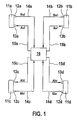
- FIG. 1 schematically shows the braking system of the vehicle.
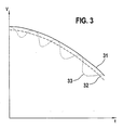
- the FIG. 2 illustrates the process of the embodiment of the invention, while the FIG. 3 reveals the time course of individual wheel speeds or the vehicle speed.
- FIG. 1 shows by the reference numeral 11a to d four wheels of a two-axle vehicle, each wheel having a designated by the reference numeral 12a to d wheel speed sensor.
- the wheel speeds Nij are supplied through lines 14a to d of the evaluation unit 16.
- Each wheel 11a-d is assigned wheel brakes 13a-d whose braking force or braking effect is controlled by the evaluation unit 16 through the lines 15a-d.
- the drive signals Aij are not shown in the FIG. 1 .
- the driver-actuated brake pedal by which the driver specifies a deceleration request of a certain extent.
- the FIG. 1 schematically shows a braking system that at individual wheel brakes, the braking effect can vary independently of the driver.
- step 22 After the starting step 21, the wheel speeds Nij and the drive signals Aij are read in step 22.
- step 23 it is queried whether the ⁇ -split driving situation described above exists.
- a ⁇ -split driving situation can be recognized, for example, by the fact that only one of the vehicle wheels is in an instability control. For this purpose, however, it must be distinguished whether the vehicle is cornering or moves substantially straight ahead. This curve recognition can be done for example by the filtered difference of the speeds on the right and left side of the vehicle.
- a ⁇ -split situation during cornering can be recognized, for example, by the fact that the wheel on the outside of the curve, which is generally subject to a higher load than the inside wheel, first enters an instability control. If, however, the inside wheel first enters an instability control, then, for driving dynamic reasons, no intervention by a special ⁇ -split brake control is generally required. In this case, proceed directly to the final step 25.
- the aforementioned slip control ( ⁇ control) is selected.
- the brake slip ⁇ is set at the high wheels, for example, to 1 to 5%.
- the wheel is then not regulated above the maximum of the ⁇ -slip curve.
- Vref is the vehicle reference speed representing the vehicle longitudinal speed.
- an instability control is made, which means that due to the wheel deceleration and the brake slip, a blocking tendency on the low ⁇ side is prevented.
- the wheel is controlled by the maximum of the ⁇ -slip curve.
- the essence of the invention is that at the low wheel of the rear axle initially also an instability control is made, which is modified so that the brake pressure drops of the low-wheel on the front axle and the low wheel of the rear axle are performed.
- Vref As the vehicle reference speed Vref, which is essential for the slip determination, during the control shown in step 24, substantially the wheel speed of the low wheel on the rear axle is used.
- the FIG. 3 shows first the time course 31 of the vehicle longitudinal speed or the vehicle reference speed.
- the reference numeral 32 the wheel rotational speeds of the high wheels are located on the front and rear axles. Due to the substantially constant distance to the vehicle reference speed 31 it can be seen that the high wheels of the front and rear axles are operated in a slip control.
- the braking effect is set at these wheels so that a brake slip of about 1% to 5% is present.
- the slip threshold must not be constant over the duration of the braking.
- the reference numeral 33 shows the wheel rotational speed of the low wheel on the front axle. It can be seen that this low-wheel on the front axle is brought up to the instability limit and by reducing the braking effect, the wheel speed of the low-wheel on the front axle is again brought up to the vehicle reference speed.
- the invention consists in the fact that the Brems decisivsabbauten also acts on the low-wheel of the rear axle on the low-wheel of the front axle also brems decisivsab constitud.
- the low-wheel is braked on the rear axle so that the rotational speed of the low-wheel can be used at the rear axle as the vehicle reference speed, which advantageously affects the slip control on the high-wheels of the front and rear axles.
Landscapes
- Engineering & Computer Science (AREA)
- Transportation (AREA)
- Mechanical Engineering (AREA)
- Regulating Braking Force (AREA)
- Braking Arrangements (AREA)
Claims (8)
- Procédé de réglage de l'action de freinage sur les roues d'un véhicule automobile qui présente au moins un essieu arrière et un essieu avant ainsi que deux roues (11a-d) situées respectivement à droite et à gauche de la direction de déplacement et à chacune desquelles est associé un dispositif de freinage (13a-d) qui applique une action de freinage sur la roue, dans lequel- des grandeurs (Nij) de vitesse de rotation qui représentent les déplacements de rotation des roues sont détectées,- des signaux de commande (Aij) qui commandent les dispositifs de freinage (13a-d) au moins dans le sens d'une augmentation ou d'un abaissement de l'action de freinage sont déterminés au moins en fonction des grandeurs (Nij) de vitesse de rotation détectées et- une situation prédéterminable (µsplit) est détectée au moins en fonction des grandeurs (Nij) de vitesse de rotation détectées si des valeurs de frottement différentes prévalent d'une manière déterminée sur les roues gauches et les roues droites,caractérisé en ce que
lorsque la situation prédéterminable (µsplit) est détectée:- la commande (Aij) a lieu sur le dispositif de freinage (13a-d) de la roue de l'essieu arrière sur laquelle une plus petite valeur de frottement prévaut (roue dite "basse"), de telle sorte quela diminution de l'action de freinage sur cette roue de l'essieu arrière (roue dite "basse") est réalisée en fonction de la diminution de l'action de freinage sur la roue située du même côté sur l'essieu avant ouaucune action de freinage n'est appliquée sur cette roue de l'essieu arrière (roue dite "basse") et- la commande (Aij) des dispositifs de freinage (13a-d) des roues de l'essieu avant et de l'essieu arrière sur lesquelles une plus grande valeur de frottement prévaut (roues dites "hautes") s'effectue en établissant un glissement prédéterminé de freinage, en formant en particulier le glissement de freinage en fonction des grandeurs de vitesse de rotation et en comparant le glissement de freinage à une valeur de seuil, la commande du dispositif de freinage de ces roues (roues dites "hautes") étant exercée en fonction de la comparaison. - Procédé selon la revendication 1, caractérisé en ce que pour régler le glissement de freinage, au moins le glissement de freinage sur ces roues (roues dites "hautes") de l'essieu avant et de l'essieu arrière est déterminé en fonction de la grandeur de vitesse de rotation qui représente les déplacements de rotation de la roue de l'essieu arrière qui présente une plus petite valeur de frottement (roue dite "basse"), en faisant en particulier intervenir comme vitesse du véhicule ou vitesse de référence du véhicule la grandeur de vitesse de rotation qui représente les déplacements de rotation de la roue de l'essieu arrière qui présente une plus basse valeur de frottement (roue dite "basse") dans la détermination du glissement de freinage.
- Procédé selon la revendication 1, caractérisé en ce que lorsque la situation prédéterminable (µsplit) est détectée, la commande (Aij) des dispositifs de freinage (13a-d) de la roue de l'essieu avant qui présente une plus petite valeur de frottement (roue dite "basse") s'effectue en empêchant le blocage de cette roue, en formant en particulier une valeur d'instabilité qui représente la dynamique de cette roue au moins en fonction des grandeurs de vitesse de rotation et en comparant cette valeur d'instabilité à une valeur de seuil, la commande du dispositif de freinage de cette roue étant exercée en fonction de la comparaison.
- Procédé selon la revendication 1, caractérisé en ce que le réglage de l'action de freinage s'effectue par ajustement d'une pression hydraulique de freinage et en ce que l'augmentation ou la diminution de l'action de freinage sont obtenues en augmentant et en abaissant par des commandes (Aij) appropriées de soupapes de pression la pression de freinage dans le dispositif de freinage (13a-d) des roues, en ce que les commandes (Aij) représentent en particulier la durée de l'établissement d'une pression de freinage ou une disparition de la pression de freinage et en ce que lorsque la situation prédéterminable (µsplit) est détectée, la commande (Aij) des dispositifs de freinage (13a-d) de la roue de l'essieu arrière qui présente une plus petite valeur de frottement (roue dite "basse") s'effectue en commandant la durée de la diminution de pression de freinage sur cette roue en fonction de la durée de la diminution de la pression de freinage sur la roue située du même côté sur l'essieu avant.
- Dispositif de réglage de l'action de freinage sur les roues d'un véhicule automobile qui présente au moins un essieu arrière et un essieu avant ainsi que deux roues (11a-d) situées respectivement à droite et à gauche de la direction de déplacement et à chacune desquelles est associé un dispositif de freinage (13ad) qui applique une action de freinage sur la roue, dans lequel- des détecteurs (12a-d) de vitesse de rotation sont prévus pour détecter des grandeurs (Nij) de vitesse de rotation qui représentent les déplacements de rotation des roues,- des moyens (16) sont prévus pour déterminer des signaux de commande (Aji) qui commandent au moins en fonction des grandeurs (Nij) de vitesse de rotation détectées des dispositifs de freinage (13a-d) au moins dans le sens d'une augmentation ou d'une diminution de l'action de freinage et- les moyens (16) détectent une situation prédéterminable (µsplit) au moins en fonction des grandeurs (Nij) de vitesse de rotation détectées si des valeurs de frottement différentes prévalent d'une manière définie sur les roues droites et les roues gauches,caractérisé en ce que
les moyens (16) sont conçus de telle sorte que lorsque la situation prédéterminable (µsplit) est détectée:- la commande (Aij) a lieu sur le dispositif de freinage (13a-d) de la roue de l'essieu arrière sur laquelle une plus petite valeur de frottement prévaut (roue dite "basse"), de telle sorte quela diminution de l'action de freinage sur cette roue de l'essieu arrière (roue dite "basse") est réalisée en fonction de la diminution de l'action de freinage sur la roue située du même côté sur l'essieu avant ouaucune action de freinage n'est appliquée sur cette roue de l'essieu arrière (roue dite "basse") et- la commande (Aij) des dispositifs de freinage (13a-d) des roues de l'essieu avant et de l'essieu arrière sur lesquelles une plus grande valeur de frottement prévaut (roues dites "hautes") s'effectue en établissant un glissement prédéterminé de freinage, en formant en particulier le glissement de freinage en fonction des grandeurs de vitesse de rotation et en comparant le glissement de freinage à une valeur de seuil, la commande du dispositif de freinage de ces roues (roues dites "hautes") étant exercée en fonction de la comparaison. - Dispositif selon la revendication 5, caractérisé en ce que pour régler le glissement de freinage, au moins le glissement de freinage sur ces roues de l'essieu avant et de l'essieu arrière (roues dites "hautes") est déterminé en fonction de la grandeur de vitesse de rotation qui représente les déplacements de rotation de la roue de l'essieu arrière qui présente une plus petite valeur de frottement (roue dite "basse"), en faisant en particulier intervenir comme vitesse du véhicule ou vitesse de référence du véhicule la grandeur de vitesse de rotation qui représente les déplacements de rotation de la roue de l'essieu arrière qui présente une plus basse valeur de frottement (roue dite "basse") dans la détermination du glissement de freinage.
- Dispositif selon la revendication 5, caractérisé en ce que lorsque la situation prédéterminable (µsplit) est détectée, la commande (Aij) des dispositifs de freinage (13a-d) de la roue de l'essieu avant qui présente une plus petite valeur de frottement (roue dite "basse") s'effectue en empêchant le blocage de cette roue, en formant en particulier une valeur d'instabilité qui représente la dynamique de cette roue au moins en fonction des grandeurs de vitesse de rotation et en comparant cette valeur d'instabilité à une valeur de seuil, la commande du dispositif de freinage de cette roue étant exercée en fonction de la comparaison.
- Dispositif selon la revendication 5, caractérisé en ce que le réglage de l'action de freinage s'effectue par ajustement d'une pression hydraulique de freinage et en ce que l'augmentation ou la diminution de l'action de freinage sont obtenues en augmentant et en abaissant par des commandes (Aij) appropriées de soupapes de pression la pression de freinage dans le dispositif de freinage (13a-d) des roues, en ce que les commandes (Aij) représentent en particulier la durée de l'établissement d'une pression de freinage ou une disparition de la pression de freinage et en ce que lorsque la situation prédéterminable (µsplit) est détectée, la commande (Aij) des dispositifs de freinage (13a-d) de la roue de l'essieu arrière qui présente une plus petite valeur de frottement (roue dite "basse") s'effectue en commandant la durée de la diminution de pression de freinage sur cette roue en fonction de la durée de la diminution de la pression de freinage sur la roue située du même côté sur l'essieu avant.
Applications Claiming Priority (2)
| Application Number | Priority Date | Filing Date | Title |
|---|---|---|---|
| DE19955243A DE19955243A1 (de) | 1999-11-17 | 1999-11-17 | Verfahren und Vorrichtung zur Einstellung der Bremswirkung bei einem Kraftfahrzeug |
| DE19955243 | 1999-11-17 |
Publications (3)
| Publication Number | Publication Date |
|---|---|
| EP1101675A2 EP1101675A2 (fr) | 2001-05-23 |
| EP1101675A3 EP1101675A3 (fr) | 2002-09-11 |
| EP1101675B1 true EP1101675B1 (fr) | 2010-07-07 |
Family
ID=7929312
Family Applications (1)
| Application Number | Title | Priority Date | Filing Date |
|---|---|---|---|
| EP00117765A Expired - Lifetime EP1101675B1 (fr) | 1999-11-17 | 2000-08-18 | Procédé et dispositif d'ajustement de l'effet de freinage dans un véhicule |
Country Status (4)
| Country | Link |
|---|---|
| US (1) | US6375280B1 (fr) |
| EP (1) | EP1101675B1 (fr) |
| JP (1) | JP4954364B2 (fr) |
| DE (2) | DE19955243A1 (fr) |
Families Citing this family (5)
| Publication number | Priority date | Publication date | Assignee | Title |
|---|---|---|---|---|
| US20040201272A1 (en) * | 2003-04-08 | 2004-10-14 | Delphi Technologies Inc. | ABS yaw control with yaw rate sensor |
| JP2013524120A (ja) * | 2010-04-08 | 2013-06-17 | シェフラー テクノロジーズ アクチエンゲゼルシャフト ウント コンパニー コマンディートゲゼルシャフト | 自動化されたクラッチを制御する方法 |
| JP5447447B2 (ja) * | 2011-07-14 | 2014-03-19 | トヨタ自動車株式会社 | 車両用制動力制御装置 |
| JP5644752B2 (ja) * | 2011-12-22 | 2014-12-24 | トヨタ自動車株式会社 | 制動力制御装置 |
| DE102014215306A1 (de) * | 2014-08-04 | 2016-02-04 | Robert Bosch Gmbh | Verfahren und Vorrichtung zum Betreiben eines Fahrzeugs |
Family Cites Families (9)
| Publication number | Priority date | Publication date | Assignee | Title |
|---|---|---|---|---|
| JPS6141657A (ja) * | 1984-07-31 | 1986-02-28 | Nippon Ee B S Kk | アンチスキッド装置用液圧制御装置 |
| JPH07108657B2 (ja) * | 1987-05-16 | 1995-11-22 | 日本エ−ビ−エス株式会社 | アンチスキッド装置用液圧制御装置 |
| DE4225983C2 (de) * | 1992-08-06 | 2002-03-14 | Bosch Gmbh Robert | Verfahren zur Bremsung von Fahrzeugrädern |
| DE4410937C1 (de) * | 1994-03-29 | 1995-08-10 | Knorr Bremse Systeme | Verfahren zur Optimierung von Bremsweg und Fahrzeugstabilität von Fahrzeugen mit einem Antiblockiersystem auf Fahrbahnen mit stark unterschiedlichen Reibwerten und blockiergeschützter Bremskraftregelkreis zur Durchführung des Verfahrens |
| GB2307526A (en) * | 1995-11-27 | 1997-05-28 | Lucas Ind Plc | A braking system for a vehicle |
| JPH09193775A (ja) * | 1996-01-17 | 1997-07-29 | Unisia Jecs Corp | 4輪駆動車用アンチスキッドブレーキ制御装置 |
| DE19707106B4 (de) * | 1996-03-30 | 2008-12-04 | Robert Bosch Gmbh | System zur Ansteuerung von Bremssystemen |
| JPH10315949A (ja) * | 1997-05-16 | 1998-12-02 | Toyota Motor Corp | 車両用制動制御装置 |
| JP3072643B2 (ja) * | 1997-05-16 | 2000-07-31 | トヨタ自動車株式会社 | 車両用制動制御装置 |
-
1999
- 1999-11-17 DE DE19955243A patent/DE19955243A1/de not_active Withdrawn
-
2000
- 2000-08-18 DE DE50015954T patent/DE50015954D1/de not_active Expired - Lifetime
- 2000-08-18 EP EP00117765A patent/EP1101675B1/fr not_active Expired - Lifetime
- 2000-11-10 JP JP2000342877A patent/JP4954364B2/ja not_active Expired - Fee Related
- 2000-11-16 US US09/714,590 patent/US6375280B1/en not_active Expired - Lifetime
Also Published As
| Publication number | Publication date |
|---|---|
| JP4954364B2 (ja) | 2012-06-13 |
| EP1101675A2 (fr) | 2001-05-23 |
| JP2001163210A (ja) | 2001-06-19 |
| US6375280B1 (en) | 2002-04-23 |
| DE19955243A1 (de) | 2001-05-23 |
| DE50015954D1 (de) | 2010-08-19 |
| EP1101675A3 (fr) | 2002-09-11 |
Similar Documents
| Publication | Publication Date | Title |
|---|---|---|
| DE102009031350B4 (de) | Mehrstufige integrierte Fahrzeugbremsunterstützung für ein Kollisionsvorbereitungssystem | |
| EP1047585B1 (fr) | Procede et dispositif destines a stabiliser un vehicule, plus precisement a l'empecher de culbuter | |
| EP1334017B1 (fr) | Procede pour reguler la stabilite de conduite d'un vehicule | |
| EP1016572B1 (fr) | Dispositif et procédé de stabilisation d'un attelage de véhicules constitué d'un tracteur et d'une remorque | |
| DE3933653B4 (de) | Radschlupfregelsystem | |
| DE19703688B4 (de) | Verfahren und Vorrichtung zur Steuerung einer Bremsanlage | |
| DE4419131B4 (de) | Kraftfahrzeug, vorzugweise Personenkraftfahrzeug | |
| DE19545001B4 (de) | Verfahren zur Giermoment-Abschwächung bei einem Antiblockiersystem | |
| EP3642086B1 (fr) | Procédé destiné à déterminer les valeurs de décélération totale atteignables par actionnement de freins de roue d'un véhicule utilitaire, système de freinage destiné à la mise en oeuvre du procédé et véhicule utilitaire comprenant ce dernier | |
| DE102008032544A1 (de) | Verfahren zur Steuerung einer Bremsanlage für ein Fahrzeug | |
| EP1131235B1 (fr) | Procede et dispositif de stabilisation d'un vehicule equipe d'un systeme de freinage a controle de glissement | |
| WO2012016617A1 (fr) | Technique permettant de faire fonctionner un système de freinage dans une situation d'adhérence différenciée | |
| DE19707106A1 (de) | System zur Ansteuerung von Bremssystemen | |
| WO2005014350A1 (fr) | Dispositif de guidage longitudinal pour un vehicule a moteur par intervention sur le systeme de freinage | |
| DE102008027093B4 (de) | Technik zum Betreiben einer Bremsanlage in einer μ-Split-Situation | |
| EP1101675B1 (fr) | Procédé et dispositif d'ajustement de l'effet de freinage dans un véhicule | |
| EP1156952B1 (fr) | Dispositif et procede de regulation du glissement de roues apres detection d'un derapage | |
| DE19944333B4 (de) | Vorrichtung zur Regelung eines Giermoments | |
| DE19542295B4 (de) | Bremssystem für ein Fahrzeug | |
| EP1023211B1 (fr) | Procede et dispositif pour ameliorer la stabilite d'un vehicule et la regulation de la pression de freinage | |
| DE10207378A1 (de) | Verfahren und Vorrichtung zur Verbesserung des Bremsverhaltens | |
| DE102020213413A1 (de) | Gierratenregelungsaktivierung | |
| DE19544090C2 (de) | Verfahren zur Regelung des Bremsdrucks während adhäsionskritischer Bremsvorgänge | |
| DE102024120292A1 (de) | Bremsverfahren, elektronisches Bremssystem und Fahrzeug | |
| DE69834307T2 (de) | Verfahren zur Kraftfahrzeug-Räderbremsdrucksteuerung beim Bremsen in einer Kurve |
Legal Events
| Date | Code | Title | Description |
|---|---|---|---|
| PUAI | Public reference made under article 153(3) epc to a published international application that has entered the european phase |
Free format text: ORIGINAL CODE: 0009012 |
|
| AK | Designated contracting states |
Kind code of ref document: A2 Designated state(s): AT BE CH CY DE DK ES FI FR GB GR IE IT LI LU MC NL PT SE |
|
| AX | Request for extension of the european patent |
Free format text: AL;LT;LV;MK;RO;SI |
|
| PUAL | Search report despatched |
Free format text: ORIGINAL CODE: 0009013 |
|
| AK | Designated contracting states |
Kind code of ref document: A3 Designated state(s): AT BE CH CY DE DK ES FI FR GB GR IE IT LI LU MC NL PT SE |
|
| AX | Request for extension of the european patent |
Free format text: AL;LT;LV;MK;RO;SI |
|
| 17P | Request for examination filed |
Effective date: 20030311 |
|
| AKX | Designation fees paid |
Designated state(s): DE ES FR GB |
|
| 17Q | First examination report despatched |
Effective date: 20070503 |
|
| RIN1 | Information on inventor provided before grant (corrected) |
Inventor name: SONNTAG, EBERHARD Inventor name: POGGENBURG, RUEDIGER Inventor name: DIEHLE, STEFAN |
|
| GRAP | Despatch of communication of intention to grant a patent |
Free format text: ORIGINAL CODE: EPIDOSNIGR1 |
|
| RIC1 | Information provided on ipc code assigned before grant |
Ipc: B60T 8/1764 20060101AFI20100317BHEP |
|
| GRAS | Grant fee paid |
Free format text: ORIGINAL CODE: EPIDOSNIGR3 |
|
| GRAA | (expected) grant |
Free format text: ORIGINAL CODE: 0009210 |
|
| AK | Designated contracting states |
Kind code of ref document: B1 Designated state(s): DE ES FR GB |
|
| REG | Reference to a national code |
Ref country code: GB Ref legal event code: FG4D Free format text: NOT ENGLISH |
|
| REF | Corresponds to: |
Ref document number: 50015954 Country of ref document: DE Date of ref document: 20100819 Kind code of ref document: P |
|
| PLBE | No opposition filed within time limit |
Free format text: ORIGINAL CODE: 0009261 |
|
| STAA | Information on the status of an ep patent application or granted ep patent |
Free format text: STATUS: NO OPPOSITION FILED WITHIN TIME LIMIT |
|
| 26N | No opposition filed |
Effective date: 20110408 |
|
| GBPC | Gb: european patent ceased through non-payment of renewal fee |
Effective date: 20101007 |
|
| PG25 | Lapsed in a contracting state [announced via postgrant information from national office to epo] |
Ref country code: ES Free format text: LAPSE BECAUSE OF FAILURE TO SUBMIT A TRANSLATION OF THE DESCRIPTION OR TO PAY THE FEE WITHIN THE PRESCRIBED TIME-LIMIT Effective date: 20101018 |
|
| REG | Reference to a national code |
Ref country code: DE Ref legal event code: R097 Ref document number: 50015954 Country of ref document: DE Effective date: 20110408 |
|
| PG25 | Lapsed in a contracting state [announced via postgrant information from national office to epo] |
Ref country code: GB Free format text: LAPSE BECAUSE OF NON-PAYMENT OF DUE FEES Effective date: 20101007 |
|
| PGFP | Annual fee paid to national office [announced via postgrant information from national office to epo] |
Ref country code: FR Payment date: 20130820 Year of fee payment: 14 |
|
| REG | Reference to a national code |
Ref country code: FR Ref legal event code: ST Effective date: 20150430 |
|
| PG25 | Lapsed in a contracting state [announced via postgrant information from national office to epo] |
Ref country code: FR Free format text: LAPSE BECAUSE OF NON-PAYMENT OF DUE FEES Effective date: 20140901 |
|
| PGFP | Annual fee paid to national office [announced via postgrant information from national office to epo] |
Ref country code: DE Payment date: 20191021 Year of fee payment: 20 |
|
| REG | Reference to a national code |
Ref country code: DE Ref legal event code: R071 Ref document number: 50015954 Country of ref document: DE |