EP1101677A1 - Bremsregelgerät - Google Patents
Bremsregelgerät Download PDFInfo
- Publication number
- EP1101677A1 EP1101677A1 EP00125443A EP00125443A EP1101677A1 EP 1101677 A1 EP1101677 A1 EP 1101677A1 EP 00125443 A EP00125443 A EP 00125443A EP 00125443 A EP00125443 A EP 00125443A EP 1101677 A1 EP1101677 A1 EP 1101677A1
- Authority
- EP
- European Patent Office
- Prior art keywords
- brake
- pressure
- braking force
- control
- sensor
- Prior art date
- Legal status (The legal status is an assumption and is not a legal conclusion. Google has not performed a legal analysis and makes no representation as to the accuracy of the status listed.)
- Withdrawn
Links
- 239000012530 fluid Substances 0.000 claims description 28
- 230000000881 depressing effect Effects 0.000 claims description 22
- 230000008859 change Effects 0.000 claims description 9
- 230000000994 depressogenic effect Effects 0.000 claims description 5
- 230000015654 memory Effects 0.000 claims description 4
- 230000004044 response Effects 0.000 claims description 4
- 238000000034 method Methods 0.000 description 44
- 230000008569 process Effects 0.000 description 43
- 230000006399 behavior Effects 0.000 description 4
- 230000009467 reduction Effects 0.000 description 4
- 239000000446 fuel Substances 0.000 description 2
- 230000006870 function Effects 0.000 description 2
- 230000002411 adverse Effects 0.000 description 1
- 239000010426 asphalt Substances 0.000 description 1
- 238000010276 construction Methods 0.000 description 1
- 230000003111 delayed effect Effects 0.000 description 1
- 238000010586 diagram Methods 0.000 description 1
- 230000003287 optical effect Effects 0.000 description 1
- 230000010349 pulsation Effects 0.000 description 1
- 230000000087 stabilizing effect Effects 0.000 description 1
Images





Classifications
-
- B—PERFORMING OPERATIONS; TRANSPORTING
- B60—VEHICLES IN GENERAL
- B60T—VEHICLE BRAKE CONTROL SYSTEMS OR PARTS THEREOF; BRAKE CONTROL SYSTEMS OR PARTS THEREOF, IN GENERAL; ARRANGEMENT OF BRAKING ELEMENTS ON VEHICLES IN GENERAL; PORTABLE DEVICES FOR PREVENTING UNWANTED MOVEMENT OF VEHICLES; VEHICLE MODIFICATIONS TO FACILITATE COOLING OF BRAKES
- B60T13/00—Transmitting braking action from initiating means to ultimate brake actuator with power assistance or drive; Brake systems incorporating such transmitting means, e.g. air-pressure brake systems
- B60T13/10—Transmitting braking action from initiating means to ultimate brake actuator with power assistance or drive; Brake systems incorporating such transmitting means, e.g. air-pressure brake systems with fluid assistance, drive, or release
- B60T13/66—Electrical control in fluid-pressure brake systems
- B60T13/68—Electrical control in fluid-pressure brake systems by electrically-controlled valves
- B60T13/686—Electrical control in fluid-pressure brake systems by electrically-controlled valves in hydraulic systems or parts thereof
-
- B—PERFORMING OPERATIONS; TRANSPORTING
- B60—VEHICLES IN GENERAL
- B60T—VEHICLE BRAKE CONTROL SYSTEMS OR PARTS THEREOF; BRAKE CONTROL SYSTEMS OR PARTS THEREOF, IN GENERAL; ARRANGEMENT OF BRAKING ELEMENTS ON VEHICLES IN GENERAL; PORTABLE DEVICES FOR PREVENTING UNWANTED MOVEMENT OF VEHICLES; VEHICLE MODIFICATIONS TO FACILITATE COOLING OF BRAKES
- B60T13/00—Transmitting braking action from initiating means to ultimate brake actuator with power assistance or drive; Brake systems incorporating such transmitting means, e.g. air-pressure brake systems
- B60T13/10—Transmitting braking action from initiating means to ultimate brake actuator with power assistance or drive; Brake systems incorporating such transmitting means, e.g. air-pressure brake systems with fluid assistance, drive, or release
- B60T13/66—Electrical control in fluid-pressure brake systems
- B60T13/662—Electrical control in fluid-pressure brake systems characterised by specified functions of the control system components
-
- B—PERFORMING OPERATIONS; TRANSPORTING
- B60—VEHICLES IN GENERAL
- B60T—VEHICLE BRAKE CONTROL SYSTEMS OR PARTS THEREOF; BRAKE CONTROL SYSTEMS OR PARTS THEREOF, IN GENERAL; ARRANGEMENT OF BRAKING ELEMENTS ON VEHICLES IN GENERAL; PORTABLE DEVICES FOR PREVENTING UNWANTED MOVEMENT OF VEHICLES; VEHICLE MODIFICATIONS TO FACILITATE COOLING OF BRAKES
- B60T7/00—Brake-action initiating means
- B60T7/02—Brake-action initiating means for personal initiation
- B60T7/04—Brake-action initiating means for personal initiation foot actuated
- B60T7/042—Brake-action initiating means for personal initiation foot actuated by electrical means, e.g. using travel or force sensors
-
- B—PERFORMING OPERATIONS; TRANSPORTING
- B60—VEHICLES IN GENERAL
- B60T—VEHICLE BRAKE CONTROL SYSTEMS OR PARTS THEREOF; BRAKE CONTROL SYSTEMS OR PARTS THEREOF, IN GENERAL; ARRANGEMENT OF BRAKING ELEMENTS ON VEHICLES IN GENERAL; PORTABLE DEVICES FOR PREVENTING UNWANTED MOVEMENT OF VEHICLES; VEHICLE MODIFICATIONS TO FACILITATE COOLING OF BRAKES
- B60T7/00—Brake-action initiating means
- B60T7/12—Brake-action initiating means for automatic initiation; for initiation not subject to will of driver or passenger
- B60T7/122—Brake-action initiating means for automatic initiation; for initiation not subject to will of driver or passenger for locking of reverse movement
-
- B—PERFORMING OPERATIONS; TRANSPORTING
- B60—VEHICLES IN GENERAL
- B60T—VEHICLE BRAKE CONTROL SYSTEMS OR PARTS THEREOF; BRAKE CONTROL SYSTEMS OR PARTS THEREOF, IN GENERAL; ARRANGEMENT OF BRAKING ELEMENTS ON VEHICLES IN GENERAL; PORTABLE DEVICES FOR PREVENTING UNWANTED MOVEMENT OF VEHICLES; VEHICLE MODIFICATIONS TO FACILITATE COOLING OF BRAKES
- B60T8/00—Arrangements for adjusting wheel-braking force to meet varying vehicular or ground-surface conditions, e.g. limiting or varying distribution of braking force
- B60T8/32—Arrangements for adjusting wheel-braking force to meet varying vehicular or ground-surface conditions, e.g. limiting or varying distribution of braking force responsive to a speed condition, e.g. acceleration or deceleration
- B60T8/321—Arrangements for adjusting wheel-braking force to meet varying vehicular or ground-surface conditions, e.g. limiting or varying distribution of braking force responsive to a speed condition, e.g. acceleration or deceleration deceleration
- B60T8/3255—Systems in which the braking action is dependent on brake pedal data
- B60T8/3275—Systems with a braking assistant function, i.e. automatic full braking initiation in dependence of brake pedal velocity
-
- B—PERFORMING OPERATIONS; TRANSPORTING
- B60—VEHICLES IN GENERAL
- B60T—VEHICLE BRAKE CONTROL SYSTEMS OR PARTS THEREOF; BRAKE CONTROL SYSTEMS OR PARTS THEREOF, IN GENERAL; ARRANGEMENT OF BRAKING ELEMENTS ON VEHICLES IN GENERAL; PORTABLE DEVICES FOR PREVENTING UNWANTED MOVEMENT OF VEHICLES; VEHICLE MODIFICATIONS TO FACILITATE COOLING OF BRAKES
- B60T8/00—Arrangements for adjusting wheel-braking force to meet varying vehicular or ground-surface conditions, e.g. limiting or varying distribution of braking force
- B60T8/32—Arrangements for adjusting wheel-braking force to meet varying vehicular or ground-surface conditions, e.g. limiting or varying distribution of braking force responsive to a speed condition, e.g. acceleration or deceleration
- B60T8/34—Arrangements for adjusting wheel-braking force to meet varying vehicular or ground-surface conditions, e.g. limiting or varying distribution of braking force responsive to a speed condition, e.g. acceleration or deceleration having a fluid pressure regulator responsive to a speed condition
- B60T8/36—Arrangements for adjusting wheel-braking force to meet varying vehicular or ground-surface conditions, e.g. limiting or varying distribution of braking force responsive to a speed condition, e.g. acceleration or deceleration having a fluid pressure regulator responsive to a speed condition including a pilot valve responding to an electromagnetic force
- B60T8/3615—Electromagnetic valves specially adapted for anti-lock brake and traction control systems
- B60T8/3655—Continuously controlled electromagnetic valves
-
- B—PERFORMING OPERATIONS; TRANSPORTING
- B60—VEHICLES IN GENERAL
- B60T—VEHICLE BRAKE CONTROL SYSTEMS OR PARTS THEREOF; BRAKE CONTROL SYSTEMS OR PARTS THEREOF, IN GENERAL; ARRANGEMENT OF BRAKING ELEMENTS ON VEHICLES IN GENERAL; PORTABLE DEVICES FOR PREVENTING UNWANTED MOVEMENT OF VEHICLES; VEHICLE MODIFICATIONS TO FACILITATE COOLING OF BRAKES
- B60T8/00—Arrangements for adjusting wheel-braking force to meet varying vehicular or ground-surface conditions, e.g. limiting or varying distribution of braking force
- B60T8/32—Arrangements for adjusting wheel-braking force to meet varying vehicular or ground-surface conditions, e.g. limiting or varying distribution of braking force responsive to a speed condition, e.g. acceleration or deceleration
- B60T8/34—Arrangements for adjusting wheel-braking force to meet varying vehicular or ground-surface conditions, e.g. limiting or varying distribution of braking force responsive to a speed condition, e.g. acceleration or deceleration having a fluid pressure regulator responsive to a speed condition
- B60T8/42—Arrangements for adjusting wheel-braking force to meet varying vehicular or ground-surface conditions, e.g. limiting or varying distribution of braking force responsive to a speed condition, e.g. acceleration or deceleration having a fluid pressure regulator responsive to a speed condition having expanding chambers for controlling pressure, i.e. closed systems
- B60T8/4275—Pump-back systems
-
- Y—GENERAL TAGGING OF NEW TECHNOLOGICAL DEVELOPMENTS; GENERAL TAGGING OF CROSS-SECTIONAL TECHNOLOGIES SPANNING OVER SEVERAL SECTIONS OF THE IPC; TECHNICAL SUBJECTS COVERED BY FORMER USPC CROSS-REFERENCE ART COLLECTIONS [XRACs] AND DIGESTS
- Y10—TECHNICAL SUBJECTS COVERED BY FORMER USPC
- Y10S—TECHNICAL SUBJECTS COVERED BY FORMER USPC CROSS-REFERENCE ART COLLECTIONS [XRACs] AND DIGESTS
- Y10S188/00—Brakes
- Y10S188/02—Hill holder
-
- Y—GENERAL TAGGING OF NEW TECHNOLOGICAL DEVELOPMENTS; GENERAL TAGGING OF CROSS-SECTIONAL TECHNOLOGIES SPANNING OVER SEVERAL SECTIONS OF THE IPC; TECHNICAL SUBJECTS COVERED BY FORMER USPC CROSS-REFERENCE ART COLLECTIONS [XRACs] AND DIGESTS
- Y10—TECHNICAL SUBJECTS COVERED BY FORMER USPC
- Y10S—TECHNICAL SUBJECTS COVERED BY FORMER USPC CROSS-REFERENCE ART COLLECTIONS [XRACs] AND DIGESTS
- Y10S303/00—Fluid-pressure and analogous brake systems
- Y10S303/02—Brake control by pressure comparison
- Y10S303/03—Electrical pressure sensor
-
- Y—GENERAL TAGGING OF NEW TECHNOLOGICAL DEVELOPMENTS; GENERAL TAGGING OF CROSS-SECTIONAL TECHNOLOGIES SPANNING OVER SEVERAL SECTIONS OF THE IPC; TECHNICAL SUBJECTS COVERED BY FORMER USPC CROSS-REFERENCE ART COLLECTIONS [XRACs] AND DIGESTS
- Y10—TECHNICAL SUBJECTS COVERED BY FORMER USPC
- Y10S—TECHNICAL SUBJECTS COVERED BY FORMER USPC CROSS-REFERENCE ART COLLECTIONS [XRACs] AND DIGESTS
- Y10S303/00—Fluid-pressure and analogous brake systems
- Y10S303/02—Brake control by pressure comparison
- Y10S303/03—Electrical pressure sensor
- Y10S303/04—Pressure signal used in electrical speed controlled braking circuit
Definitions
- the present invention relates to a brake control device in which brake control can be automatically executed according to a demand based on vehicle behavior in addition to a demand based on a driver's brake pedal operation.
- a braking control for stabilizing vehicle behavior such as anti-skid control
- anti-skid control when a brake pedal is depressed for braking, each vehicle wheel speed is controlled by adjusting braking hydraulic pressure of each wheel cylinder so that a slip ratio of each wheel may fall within a given range in order to obtain optimum braking force in each wheel.
- a hydraulic circuit of a bake control device is provided with electromagnetic valves such as a pressure reduce control valve P1 and a pressure increase control valve P2 for reducing hydraulic pressure of the wheel cylinder or for holding hydraulic pressure of the wheel cylinder.
- the pressure increase control valve P2 is a normally open valve (N/O valve) in which a fluid conduit is normally opened by a spring biasing force and the fluid conduit is closed when a solenoid is energized.
- the pressure reduce control valve P1 is a normally closed valve (N/C valve) in which a fluid conduit is normally closed by a spring biasing force and the fluid conduit is opened when a solenoid is energized.
- the pressure increase control valve P2 is operative to close a fluid conduit from a master cylinder P3 to a wheel cylinder P4 for holding the wheel cylinder hydraulic pressure when the pressure reducing valve P1 is closed and for reducing the wheel cylinder hydraulic pressure when the pressure reducing valve P1 is opened.
- the hydraulic circuit is also provided with a check valve P5 (return valve) in parallel to the pressure increase control valveP2 (other check valves are omitted in the drawing).
- a check valve P5 return valve
- P2 other check valves are omitted in the drawing.
- the check valve P5 serves to return the brake fluid back from a side of the wheel cylinder P4 to a side of the master cylinder P3 so that wheel cylinder pressure may be reduced to lower the braking force, resulting in a longer braking distance.
- the hydraulic circuit of the brake control device is more compact with a less number of brake components and parts but operative with better braking force holding function.
- An object of the present invention is to provide a brake control device having a compact structure with a less number of brake components and parts for executing braking force holding control.
- the brake control device has brake pressure producing means (for example, master cylinder) for producing hydraulic pressure (for example, master cylinder pressure) according to a braking operation of a vehicle driver, wheel braking force generating means (for example, wheel cylinder) for generating braking force to a wheel, a fluid conduit connecting the brake pressure producing means and thewheel braking force generatingmeans for allowing brake fluid flow between the brake pressure producing means and the wheel braking force generating means, a solenoid valve (for example, pressure increase control valve) disposed in the fluid conduit so that the fluid conduit may be provided on a side of the brake pressure producing means with a first hydraulic pressure and on a side of the braking force generating means with a second hydraulic pressure, an electric control unit, and sensor means including a pressure sensor for generating sensor signals representing vehicle states including a value of the first hydraulic pressure, all of which are input to the electric control unit.
- brake pressure producing means for example, master cylinder
- wheel braking force generating means for example, wheel cylinder
- fluid conduit connecting the brake pressure producing
- the electric control unit has memory means for receiving the sensor signal of the pressure sensor and memorizing a peak value of the first hydraulic pressure, determining means for determining from the sensor signals a necessity of a braking force holding control for holding the second hydraulic pressure higher than the first hydraulic pressure when the brake pedal happens to be returned and generating a demand signal for executing the braking force holding control, calculating means for calculating a control amount based on a difference between the peak value of the first hydraulic pressure and an actual value of the first hydraulic pressure to be lowered when the brake pedal is returned, and driving means for driving the solenoid valve so as to restrict brake fluid flow from the braking force generating means to the brake pressure producing means in response to the control amount, when the demand signal is generated, wherein, while an increasing speed of the second hydraulic pressure is substantially equal to that of the first hydraulic pressure when the brake pedal is depressed, a reducing speed of the second hydraulic pressure is lower that that of the first hydraulic pressure during a given time when the brake pedal happens to be returned.
- an anti-skid control circuit provided with a hydraulic pump connected with the fluid conduit for the first hydraulic pressure and a pressure reduce control valve connected with the fluid conduit for the second hydraulic pressure in addition to the pressure increase control valve.
- the braking force holding control is executed when the determining means generates the demand signal by determining based on the sensor signals that the driver depresses rapidly the brake pedal for sudden braking, for example, by determining that a change per time of the brake pedal movement exceeds a predetermined value.
- the braking force holding control is executed when the determining means generates the demand signal by determining that the vehicle stops on a sloping road due to the driver's brake pedal operation or that an engine of the vehicle stops as an idle stop due to the driver's brake pedal operation.
- the sensor signals to be used for determining that the vehicle stops on the sloping road are, for example, signals from a sloping sensor for detecting an inclination angle of the vehicle stopping on the sloping road (the angle is more than a predetermined value), from a brake switch (ON) for detecting the driver's brake pedal depression and from a speed sensor for detecting at least one of a vehicle speed and a wheel speed (zero speed).
- the sensor signals to be used for determining that the engine of the vehicle stops as an idle stop are, for example, signals from a sensor for detecting an engine stop (signal of fuel cut or signal of ignition stop), from a brake switch (ON) for detecting the driver's brake pedal depression and from a speed sensor for detecting at least one of a vehicle speed and a wheel speed (zero speed).
- the solenoid valve is, preferably, a two-position valve driven by the driving means so that current voltage applied thereto is controlled at a duty ratio in proportion to the control amount or a linear solenoid valve driven by the driving means so that a current amount applied thereto is controlled according to the control amount.
- a brake control device includes a hydraulic circuit for executing braking force holding control and braking force termination control in addition to a known anti-skid control and a brake assist control.
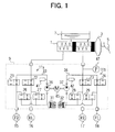
- Fig. 1 shows an outline structure of the brake control device according to the first embodiment.
- a brake pedal 5 is connected via a brake booster 3 to a tandem type master cylinder 1 and a master reservoir 7 is also connected with the master cylinder 1.
- a hydraulic circuit 9 constituting a two line diagonal piping system for adjusting brake pressure is connected with the master cylinder 1.
- the hydraulic circuit 9 has a first hydraulic conduit 11a and a second hydraulic conduit 11b.
- the master cylinder 1 is connected, via the first hydraulic conduit 11a to a wheel cylinder 15 of a front right wheel (FR) and a wheel cylinder 16 of a rear left wheel (RL) and, via the second hydraulic conduit 11b, to a wheel cylinder 17 of a rear right wheel (RR) and a wheel cylinder 18 of a front left wheel (FL).
- the first hydraulic conduit 11a is provided with a pressure increase control valve 21 and a pressure reduce control valve 26 for controlling hydraulic pressure in the FR wheel cylinder 15 and a pressure increase control valve 22 and a pressure reduce control valve 27 for controlling hydraulic pressure in the RL wheel cylinder 16.
- the second hydraulic conduit 11b is provided with a pressure increase control valve 23 and a pressure reduce control valve 28 for controlling hydraulic pressure in the RR wheel cylinder 17 and a pressure increase control valve 24 and a pressure reduce control valve 29 for controlling hydraulic pressure in the FL wheel cylinder 18.
- Each of the pressure increase control valves 21 to 24 is a normally open electromagnetic valve (holding valve) having two positions for opening and closing. Since the pressure reduce control valve is a normally close valve, each of the pressure increase control valves 21 to 24 is operative to open the hydraulic conduit due to a spring biasing force and to close the hydraulic conduit so as to hold wheel cylinder pressure due to a magnetic force when a solenoid is energized.
- the first hydraulic conduit 11a is further provided with a reservoir 31 for storing temporally brake fluid ejected from the respective pressure reduce control valves 26 and 27 and a hydraulic pump 36 for delivering with pressure brake fluid to a conduit 33.
- the conduit 33 is provided with an accumulator 41 for easing an inherent hydraulic pressure pulsation of brake fluid to be delivered from the pump 36.
- the pressure increase control valves 23 and 24, the pressure reduce control valves 28 and 29, a reservoir 32, a hydraulic pump 37 and an accumulator 42 are arranged at positions similar to those of the first hydraulic conduit 11a.
- the hydraulic pumps 36 and 37 are connected to and driven by an electric pump motor 45.
- the first embodiment there are no check valves (return valves) to be positioned in parallel to the pressure increase control valves 21 to 24, as shown in the conventional brake control device. Therefore, as described later in detail, according to a returning operation of the brake pedal 5, wheel cylinder pressure are released by adjusting opening and closing states of the respective pressure increase control valves 21 to 24 not by bypassing brake fluid of the wheel cylinders through the respective return valves.
- a pressure sensor 47 for detecting master cylinder pressure is installed in a conduit 34 extending from the master cylinder 1 to the pressure increase control valves 23 and 24 in the second hydraulic conduit 11b.
- the pressure sensor 47 may be installed in the first hydraulic conduit 11a instead of installing in the second hydraulic conduit 11b, since the master cylinder pressure is identical in each of the first and second hydraulic conduits 11a and 11b.
- the ECU 50 is provided for controlling the brake control device having the hydraulic circuit 9.
- the ECU 50 is composed of a microcomputer having well known CPU 50a, ROM 50b, RAM 50c, input-output portions 50d and bath lines 50 e. Signals from a vehicle speed sensor 51 for detecting vehicle speed, wheel speed sensors for detecting the respective rotating speeds of wheels, a brake switch 54 for detecting depression of the brake pedal 5 and a pressure sensor 47 for detecting the master cylinder pressure, are input to the ECU 50.
- Control signals for driving the electromagnetic valves of the pressure increase and reduce control valves 21 to 24 and 26 to 29 and other actuators such as a control actuator of the pump motor 45 are output from the ECU 50.
- master cylinder pressure (Pm/c) is rapidly increased so that wheel cylinder pressure (Pw/c) is sharply increased, as shown in a solid line t 0 to t 1 in Fig. 3.
- the master cylinder pressure is gradually reduced as shown in a dotted line t 1 to t 2 so that braking force may be reduced because a driver foot is too exhausted to continue the strong depression of the brake pedal or leaves the brake pedal by accident due to a strong reaction of the brake pedal and a brake pedal depressing force is reduced.
- the pressure increase control valves 21 to 24 are driven so as to secure a larger hysteresis of hydraulic pressure at a pressure reducing time. As a result, higher pressure in the wheel cylinder is continuously held for a certain time so that higher braking force may be maintained.
- each of the pressure increase control valves is driven to gradually open the conduit between the wheel cylinder and the master cylinder without making the hydraulic conduit fully open from a scratch, for example, by duty control of current voltage applied to each of the pressure increase control valves 21 to 24.
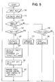
- a flow chart of Fig. 5 shows steps of braking force holding control after the peak of the master cylinder pressure at sudden braking.
- the driver's brake pedal depressing speed is rapid so that wheel cylinder pressure may be rapidly increased at an early stage of the sudden braking (braking force initial control). Further, after the braking force initial control is executed and, then, the master cylinder pressure attains the peak value, wheel cylinder pressure is controlled to hold a higher braking force for a certain time (braking force holding control), as shown later in detail.
- braking force initial control and the braking force holding control is called as brake assist control.
- Step 100 of Fig. 5 master cylinder pressure (Pm/c) is detected based on a signal of the pressure sensor 47 and recorded or memorized in RAM 50c.
- Step 110 a change rate of the master cylinder pressure (d Pm/c) is calculated to judge the sudden braking.
- Step 120 whether the brake assist control (braking force holding control) is executed is determined. If the answer is affirmative, the process goes to Step 130 and, if the answer is negative, the process goes to Step 180.
- Step 180 whether the change rate of the master cylinder pressure (d Pm/c) exceeds a reference value (KdP) for judging the sudden braking is determined. If the answer is affirmative, the process goes to Step 190 as it is presumed that the sudden braking (an initial stage of brake pedal depressing for the sudden braking) is operated. If the answer is negative, the process returns back to the Step 100 in a presumption that the sudden braking is not operated.
- KdP change rate of the master cylinder pressure
- brake assist control starts, if necessary and demanded, by detecting a fact of the early stage of sudden braking. Then, the process returns to the Step 100.
- the braking force initial control is executed at the early stage of sudden braking in such a manner that high master cylinder pressure is applied via the pressure increase control valves 21 to 24 to the respective wheel cylinders 15 to 18 to rapidly increase the braking force.
- Step 130 next to the Step 120 at which it is determined that the brake assist control (braking force holding control) is under way, whether the master cylinder pressure (Pm/c) is below a reference value (KP) for judging a termination of the brake assist control is determined. If determined affirmatively, the process goes to Step 170 in a presumption that the brake assist control (including the braking force initial control and the braking force holding control) has terminated. If the answer is negative, the process goes to Step 140 in a presumption that the brake assist control continues.
- Pm/c master cylinder pressure
- KP reference value
- Step 170 a control for terminating the brake assist control is executed and, then, the process returns back to the Step 100.
- current supply to solenoids of the pressure increase control valves 21 to 24 are shut off so as to fully open the brake fluid conduit.
- wheel cylinder pressure is rapidly lowered to coincide to the master cylinder pressure. In this case, there occurs no hysteresis between changes of the master and wheel cylinder pressure.
- the peak value (Pm/c peak) of master cylinder pressure is calculated as the brake assist control continues. That is, the peak value of master cylinder pressureiscalculatedbasedonadetectedvalueofthepressure sensor 47 to find out a point (Pm/c peak in Fig. 3) where master cylinder pressure is changed from an increasing state to a reducing state.
- the master cylinder pressure may be reduced after a lapse of a certain time during which the driver strongly depresses the brake pedal when the driver's brake pedal depressing force is released due to a reaction force of the brake pedal. Accordingly, a peak point of the master cylinder pressure where the increasing state is changed to the reducing state is detected.
- the calculation process at the Step 140 is not always necessary and may be omitted since the memorized value showing the peak point may be utilized for the subsequent calculation of a target pressure difference (this process is also applied to the other embodiments to be described later) .
- the target pressure difference ⁇ P is calculated for braking force holding control in which higher wheel cylinder pressure (higher braking force)is held even after master cylinder pressure shows the peak and is reduced.
- the target pressure difference ⁇ P is a difference between the peak value (Pm/c peak) and actual master cylinder pressure(pm/c shown in a dotted line of Fig. 3) reducing.
- Step 160 is for calculating a duty ratio of current voltage that is applied to the respective solenoids of the pressure increase control valve 21 to 24 for maintaining wheel cylinder pressure higher by a predetermined value to be decided based on the target pressure difference ⁇ P than actual master cylinder pressure.
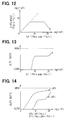
- the predetermined value to be decided based on the target pressure difference ⁇ P is, for example, as shown in Fig. 12 in which a relationship between the target pressure difference AP and the difference pressure by which wheel cylinder pressure is higher than actual master cylinder pressure Pm/c is shown.
- Step 165 braking force holding control is executed by applying current voltage to the solenoids of the pressure increase control valves 21 to 24 so as to realize the duty ratio control mentioned above. Then, the process returns to the Step 100.
- the pressure increase control valves 21 to 24 are not fully opened at once and bring the hysteresis as shown in Fig. 4B. Accordingly, higher wheel cylinder pressure (higher braking force) can be maintained for a necessary period of time as shown in a solid line t 1 to t 2 of Fig. 3.
- the brake assist control is executed at sudden braking.
- a brake pedal depressing force reduction is detected by the peak value of master cylinder pressure and there is a difference between the value of actual master cylinder pressure and the peak value of master cylinder pressure, which is deemed as a demand of holding braking force
- a target value (the target pressure difference ⁇ P) for executing braking force holding control is calculated.
- braking force holding control current voltage applied to the solenoids of the pressure increase control valves 21 to 24 is duty controlled based on the target pressure difference representing a difference between the actual master cylinder pressure and the peak value of master cylinder pressure. Even if the brake pedal depressing force is reduced after the peak of master cylinder pressure, higher wheel cylinder pressure can be maintained by the braking force holding control so that higher braking force may be maintained. As a result, safety on the sudden braking may be much more enhanced.
- the return valves in parallel to the pressure increase control valves 21 to 24 are not provided. Therefore, the hydraulic circuit of the brake control device having less number of components and parts becomes more compact and may be provided at less cost, compared with that of the conventional brake control device.
- Steps 100, 110, 120, 130, 170, 180 and 190 are provided for braking force initial control and termination control at sudden braking
- a gist of the first embodiment is not limited to the case of sudden braking. Accordingly, the first embodiment may be modified to execute the braking force holding control mentioned above whenever master cylinder pressure shows the peak value P m/c peak. In this case, the Steps 100, 110, 120, 130, 170, 180 and 190 may be omitted.
- a brake control device according to a second embodiment is described hereinafter. Explanation of portions similar to those of the first embodiment is omitted or simplified.
- the brake control device can execute braking force holding control based on a demand of holding braking force when the vehicle is stopped on a sloping road and execute the subsequent braking force termination control.
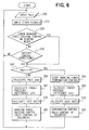
- Step 200 master cylinder pressure (pm/c), which is detected based on a signal from the pressure sensor 47, is input.
- Step 210 other signals representing various states and behaviors of vehicle, which are used for determining whether it is appropriate to execute braking force holding control on the sloping road, are input.
- a signal showing an inclination angle from a slope sensor (not shown) for detecting a state of the sloping road a signal from the brake switch 54 for detecting the driver's depression of the brake pedal 5
- a signal from a vehicle speed sensor 51 (or the wheel speed sensor 53) for detecting vehicle speed (or wheel speed) for detecting vehicle speed (or wheel speed) are all input.
- Step 220 whether braking force holding control on the sloping road is executed is determined. If the answer is affirmative, the process goes to Step 240 and, if negative, the process goes to Step 230.
- Step 230 whether conditions on executing braking force holding control on the sloping road are satisfied is determined. For example, whether the sloping road has an inclination angle more than a given angle, whether the brake pedal 5 is depressed, and whether the vehicle is in a stopping state (that is, the vehicle or wheel speed is zero) are determined. If the answers are affirmative, the process goes to Step 240 and, if negative, the process returns back to the Step 200.
- Step 240 whether master cylinder pressure (Pm/c) is below a reference value (KP in Fig. 7) for terminating braking force holding control on the sloping road is determined.
- Pm/c master cylinder pressure
- KP in Fig. 7 a reference value for terminating braking force holding control on the sloping road is determined. The process goes to Step 290, if the answer is affirmative, and to Step 250, if the answer is negative.
- the peak value is used for this control.
- a target pressure difference ⁇ P1 is calculated.
- a difference between the peak value (Pm/c peak) of master cylinder pressure and an actual value (Pm/c) of master cylinder pressure reducing is calculated as the target pressure difference ⁇ P1.
- a duty ratio of current voltage that is applied to the respective solenoids of the pressure increase control valves 21 to 24 is calculated according to a map or a calculation formula based on the target pressure difference ⁇ P1.
- Step 280 braking force holding control is executed by applying current voltage to the solenoids of the pressure increase control valves 21 to 24 and, then, the process returns to the Step 200.
- Step 290 control necessary for terminating the braking force holding control is executed at Step 290.
- This termination control is not for fully opening the pressure increase control valves 21 to 24 as shown in the first embodiment, but for executing control similar to braking force holding control on the sloping road mentioned above.
- a target pressure difference ⁇ P2 for braking force termination control is calculated. That is, to execute braking force termination control in which wheel cylinder pressure(braking force)is maintained with a given slope, a difference between the reference master cylinder pressure (KP) and an actual master cylinder pressure sharply lowering is calculated as the target pressure difference ⁇ P2.
- FIG. 14 A chart comparing a relationship between a target pressure difference ⁇ P2 and a duty ratio of pressure increase control valve with a relationship between a target pressure difference ⁇ P1 and a duty ratio of pressure increase control valve is shown in Fig. 14. According to this chart, the duty ratio corresponding to the target pressure difference ⁇ P2 is set so as to make the pressure increase control valve more open so that pressure difference between wheel cylinder pressure (Pw/c) andmaster cylinder pressure (Pm/c) is smaller, compared to the duty ratio corresponding to the target pressure difference ⁇ P1.
- a duty ratio of current voltage that is applied to the respective solenoids of the pressure increase control valve 21 to 24 is calculated according to a map or a calculation formula based on the target pressure difference ⁇ P2.
- Step 320 current voltage, which can realize the duty ratio mentioned above, is applied to the solenoids of the pressure increase control valves 21 to 24 to execute braking force termination control and, then, the process returns to the step 200.
- wheel cylinder pressure is not lowered rapidly as is in the conventional brake control device, but gradually reduced by braking force termination control.
- the vehicle may maintain the stopping state on the sloping road even if the brake pedal is once returned for resetting so that driving safety on the sloping road may be improved.
- a brake control device according to a third embodiment is described hereinafter. Explanation of portions similar to those of the first embodiment is omitted or simplified.
- the brake control device can execute braking force holding control based on a demand of holding braking force at an idle stop and the subsequent braking force termination control.
- Step 400 master cylinder pressure (pm/c), which is detected based on a signal from the pressure sensor 47, is input.
- Step 410 other signals representing various states and behaviors of vehicle, which are used for determining whether it is appropriate to execute braking force holding control at the idle stop, are input.
- a signal showing an engine revolution sensor (not shown) for detecting the engine stop (or a signal showing fuel cut or ignition stop)
- a signal from the brake switch 54 for detecting the driver's depression of the brake pedal 5
- a signal from a vehicle speed sensor 51 or the wheel speed sensor 53 for detecting vehicle speed (or wheel speed) for detecting vehicle speed (or wheel speed) for detecting vehicle speed (or wheel speed)
- a signal showing an engine revolution sensor for detecting the engine stop (or a signal showing fuel cut or ignition stop)
- a signal from the brake switch 54 for detecting the driver's depression of the brake pedal 5
- a signal from a vehicle speed sensor 51 or the wheel speed sensor 53
- Step 420 whether braking force holding control at the idle stop is executed is determined. If the answer is affirmative, the process goes to Step 440 and, if negative, the process goes to Step 430.
- Step 430 whether conditions on executing braking force holding control at the idle stop are satisfied is determined. For example, whether the engine is in an idling state, whether the brake pedal 5 is depressed, and whether the vehicle is in a stopping state (that is, the vehicle or wheel speed is zero) are determined. If the answers are affirmative (at a time t 1 of Fig. 9), the process goes to Step 440 and, if negative, the process returns back to the Step 400.
- Step 440 whether master cylinder pressure (Pm/c) is below a reference value (KP in Fig. 9) for terminating braking force holding control at the idle stop is determined.
- the process goes to Step 490, if the answer is affirmative, and to Step 450, if the answer is negative.
- a boosting operation of the booster is adversely affected since the engine stops and intake manifold negative pressure is cancelled.
- driver's brake pedal depression is released so that there exists the peak of master cylinder pressure.
- the peak value is used for this control.
- a target pressure difference ⁇ P1 is calculated.
- a difference between the peak value (Pm/c peak) of master cylinder pressure and an actual value (Pm/c) of master cylinder pressure reducing is calculated as the target pressure difference ⁇ P1.
- a duty ratio of current voltage that is applied to the respective solenoids of the pressure increase control valves 21 to 24 is calculated according to a map or a calculation formula based on the target pressure difference ⁇ P1.
- Step 480 braking force holding control is executed by applying current voltage to the solenoids of the pressure increase control valves 21 to 24 and, then, the process returns to the Step 200.
- Step 440 As the negative answer at the Step 440 means a termination time (a time t 2 of Fig. 9) of braking force holding control at the idle stop, control necessary for terminating the braking force holding control is executed at Step 490.
- This termination control is not for fully opening the pressure increase control valves 21 to 24 as shown in the first embodiment, but for executing control similar to braking force holding control at the idle stop mentioned above.
- a target pressure difference ⁇ P2 for braking force termination control is calculated. That is, to execute braking force termination control in which wheel cylinder pressure (braking force)is maintained with a given slope, a difference between the reference master cylinder pressure (KP) and an actual master cylinder pressure sharply lowering is calculated as the target pressure difference ⁇ P2.
- a duty ratio of current voltage that is applied to the respective solenoids of the pressure increase control valve 21 to 24 is calculated according to a map or a calculation formula based on the target pressure difference ⁇ P2.
- Step 520 current voltage, which can realize the duty ratio mentioned above, is applied to the solenoids of the pressure increase control valves 21 to 24 to execute braking force termination control and, then, the process returns to the step 400.
- the pressure increase control valves 21 to 24 serves to hold wheel cylinder pressure sufficiently so that higher braking force may be secured.
- wheel cylinder pressure is not lowered rapidly as is in the conventional brake control device, but gradually reduced by braking force termination control.
- the vehicle may maintain the stopping state at the idle stop even if the brake pedal is once returned for resetting so that driving safety at the idle stop may be improved.
- a brake control device according to a fourth embodiment is described hereinafter. Explanation of portions similar to those of the first embodiment is omitted or simplified.
- a brake control device has a hydraulic circuit whose construction is a little different from that of the first embodiment.
- pressure increase control valves 51 to 54 are linear solenoid valves whose each valve opening degree is changed in proportion to a current amount to be supplied to each of the solenoids.
- the solenoids of the pressure increase control valves 51 to 54 are not energized by current, the valves are operative to open the fluid conduit by their own spring force and, when the solenoids are energized, to close the fluid conduit in proportion to the current amount supplied thereto. Therefore, after wheel cylinder pressure is increased by master cylinder pressure, wheel cylinder pressure may be adequately held by controlling the current amount supplied to the solenoids of the pressure increase control valves 51 to 54.
- Control processes of the braking force initial control and the subsequent braking force holding control according to the fourth embodiment are nearly same as those of the first embodiment.
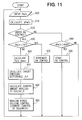
- Step 600 master cylinder pressure (Pm/c) detected based on a signal of the pressure sensor 47 is input.
- a change rate of the master cylinder pressure (d Pm/c) is calculated to judge the sudden braking.
- Step 620 whether the brake assist control is executed is determined. If the answer is affirmative, the process goes to Step 630 and, if the answer is negative, the process goes to Step 680.
- Step 680 whether the change rate of the master cylinder pressure (d Pm/c) exceeds a reference value (KdP) for judging the sudden braking is determined. If the answer is affirmative, the process goes to Step 690 as it is presumed that the sudden braking (an initial stage of brake pedal depressing for the sudden braking) is operated. If the answer is negative, the process returns back to the Step 600 in a presumption that the sudden braking is not operated.
- KdP change rate of the master cylinder pressure
- brake assist control (braking force initial control) starts, if necessary, according to the demand because of the early stage of sudden braking. Then, the process returns to the Step 600.
- Step 690 brake assist control (braking force initial control) starts, if necessary and demanded, by detecting a fact of the early stage of sudden braking. Then, the process returns to the Step 600.
- Step 630 next to the Step 620 at which it is determined that the brake assist control is under way, whether the master cylinder pressure (Pm/c) is below a reference value (KP) for judging a termination of the brake assist control is determined. If determined affirmatively, the process goes to Step 670 in a presumption that the brake assist control (including the braking force initial control and the braking force holding control) has terminated. If the answer is negative, the process goes to Step 640 in a presumption that the brake assist control continues.
- Step 670 a control for terminating the brake assist control is executed and, then, the process returns back to the Step 600.
- the current amount supplied to the solenoids of the pressure increase control valves 51 to 54 becomes zero [0] so as to fully open the brake fluid conduit.
- a peak value (Pm/c peak) of master cylinder pressure is calculated.
- a target pressure difference ⁇ P which is a difference between the peak value (Pm/c peak) of master cylinder pressure and actual master cylinder pressure (Pm/c) gradually reducing, is calculated.
- Step 660 the current amount applied to the respective solenoids of the pressure increase control valve 51 to 54 for maintaining wheel cylinder pressure higher by the target pressure difference ⁇ P than actual master cylinder pressure is calculated.
- a relationship between the target pressure difference AP and the current amount is memorized in advance in ROM 50b as a map or a calculation formula. Accordingly, the current amount corresponding to the target pressure difference ⁇ P calculated may be obtained with reference to, for example, the map.
- Step 665 braking force holding control is executed by applying the current amount to the solenoids of the pressure increase control valves 51 to 54. Then, the process returns to the Step 600.
- the current amount supplied to the solenoids of pressure increase control valves 51 to 54 is controlled for executing braking force holding control so that a difference between master cylinder pressure and wheel cylinder pressure may correspond to the target pressure difference ⁇ P.
- the fourth embodiment as the necessary braking force at sudden braking is held by controlling the current amount for the pressure increase control valves 51 to 54, the return valves in parallel to the pressure increase control valves 51 to 54 are not provided. Therefore, the hydraulic circuit of the brake control device having less number of components and parts becomes more compact and may be provided at less cost, compared with that of the conventional brake control device.
- the braking force termination control may be executed after braking force holding control.
- braking force termination control may be omitted and only braking force holding control is executed.
- a recording medium for recording processes programs or memories for executing the control mentioned above, not only ECU composed of the microcomputer but also a microchip, a floppy disk, a hard disk and an optical disk may be used.
- driver's brake pedal depressing force may be detected and the detected depressing force may be used as a replacement of master cylinder pressure.
- the peak value Pm/c peak of master cylinder pressure and the actual value of the master cylinder pressure (pm/c) reducing instead of the peak value Pm/c peak of master cylinder pressure and the actual value of the master cylinder pressure (pm/c) reducing, a peak value of the depressing force and an actual value of the depressing force reducing may be used.
- the calculated target pressure difference based on the Driver's brake pedal depressing force may be used for duty ratio control or current amount control of the pressure increase control valve.
Landscapes
- Engineering & Computer Science (AREA)
- Transportation (AREA)
- Mechanical Engineering (AREA)
- Physics & Mathematics (AREA)
- Electromagnetism (AREA)
- Fluid Mechanics (AREA)
- Regulating Braking Force (AREA)
Applications Claiming Priority (2)
| Application Number | Priority Date | Filing Date | Title |
|---|---|---|---|
| JP32981599 | 1999-11-19 | ||
| JP32981599 | 1999-11-19 |
Publications (1)
| Publication Number | Publication Date |
|---|---|
| EP1101677A1 true EP1101677A1 (de) | 2001-05-23 |
Family
ID=18225551
Family Applications (1)
| Application Number | Title | Priority Date | Filing Date |
|---|---|---|---|
| EP00125443A Withdrawn EP1101677A1 (de) | 1999-11-19 | 2000-11-20 | Bremsregelgerät |
Country Status (2)
| Country | Link |
|---|---|
| US (1) | US6364436B1 (de) |
| EP (1) | EP1101677A1 (de) |
Cited By (4)
| Publication number | Priority date | Publication date | Assignee | Title |
|---|---|---|---|---|
| EP1459950A1 (de) * | 2003-03-19 | 2004-09-22 | Advics Co., Ltd. | Bremsdrucksteuervorrichtung in einer Bremsanlage |
| US8498794B2 (en) | 2006-10-31 | 2013-07-30 | Advics Co., Ltd. | Anti-skid control apparatus configured to compensate for hydraulic pressure fluctuations |
| CN109229083A (zh) * | 2018-10-12 | 2019-01-18 | 华东交通大学 | 一种制动轮缸液压力可控的电子液压制动方法 |
| CN119459609A (zh) * | 2024-12-19 | 2025-02-18 | 浙江吉利控股集团有限公司 | 踏板组件、制动方法和车辆 |
Families Citing this family (24)
| Publication number | Priority date | Publication date | Assignee | Title |
|---|---|---|---|---|
| DE10301471A1 (de) * | 2002-01-18 | 2003-08-07 | Hitachi Unisia Automotive Ltd | Vorrichtung und Verfahren zur Bremssteuerung |
| DE10250719A1 (de) * | 2002-10-31 | 2004-05-19 | Robert Bosch Gmbh | Verfahren und Vorrichtung zur Steuerung der Bremsanlage eines Kraftfahrzeugs |
| JP4367051B2 (ja) * | 2003-08-25 | 2009-11-18 | 株式会社アドヴィックス | 電気ブレーキシステム |
| US6966338B2 (en) * | 2004-01-08 | 2005-11-22 | Husco International, Inc. | Electrohydraulic valve for controlling operation of an engine cylinder valve |
| JP2006088732A (ja) * | 2004-09-21 | 2006-04-06 | Honda Motor Co Ltd | ブレーキ力保持装置 |
| DE102005029891A1 (de) * | 2005-06-27 | 2007-01-04 | Robert Bosch Gmbh | Zustandsabhängige Anhalteruck-Begrenzungsfunktion für Kfz-Bremsanlagen |
| US7600827B2 (en) * | 2005-09-23 | 2009-10-13 | Gm Global Technology Operations, Inc. | Rollback reduction in hybrid or conventional powertrain vehicle via vehicle stability enhancement system (VSES) |
| JP2007237777A (ja) * | 2006-03-06 | 2007-09-20 | Advics:Kk | 車両用ブレーキ制御装置 |
| JP4473898B2 (ja) * | 2007-07-25 | 2010-06-02 | 日信工業株式会社 | 車両用ブレーキ液圧制御装置 |
| US7934589B2 (en) * | 2008-01-24 | 2011-05-03 | Eaton Corporation | Foundation brake hill start aide system |
| JP5211921B2 (ja) * | 2008-07-31 | 2013-06-12 | 株式会社アドヴィックス | 制動力保持制御装置 |
| US8579765B2 (en) * | 2009-12-09 | 2013-11-12 | Ford Global Technologies, Llc | Hybrid electric vehicle hold function |
| US8936322B2 (en) * | 2010-04-20 | 2015-01-20 | Robert Bosch Gmbh | Brake system with selector valve for selecting between two modes of operation |
| US8192328B2 (en) * | 2010-04-30 | 2012-06-05 | Ford Global Technologies, Llc | Methods and systems for assisted direct start control |
| US8328687B2 (en) | 2010-07-09 | 2012-12-11 | Ford Global Technologies, Llc | Method for controlling an engine that may be automatically stopped |
| US8414456B2 (en) | 2010-07-09 | 2013-04-09 | Ford Global Technologies, Llc | Method for starting an engine |
| US8864623B2 (en) | 2010-07-09 | 2014-10-21 | Ford Global Technologies, Llc | Method for controlling a transmission coupled to an engine that may be automatically stopped |
| JP5563004B2 (ja) * | 2012-03-28 | 2014-07-30 | 日信工業株式会社 | 車両用ブレーキ液圧制御装置 |
| DE102012024950B4 (de) * | 2012-12-19 | 2026-02-19 | Zf Active Safety Gmbh | Hydraulisches Bremssystem mit einem Zwischenspeicher |
| WO2014157161A1 (ja) * | 2013-03-29 | 2014-10-02 | 日信工業株式会社 | 車両用ブレーキ液圧制御装置 |
| JP5856133B2 (ja) * | 2013-12-11 | 2016-02-09 | 本田技研工業株式会社 | 車両用制動システム |
| US10315640B2 (en) | 2016-12-08 | 2019-06-11 | Robert Bosch Gmbh | Vehicle having brake system and method of operating |
| DE102018205512A1 (de) * | 2018-04-12 | 2019-10-17 | Robert Bosch Gmbh | Verfahren zur Bestimmung eines Ansteuersignals für ein elektronisch steuerbares Druckmittelsteuerventil einer elektronisch schlupfregelbaren Fremdkraftbremsanlage |
| CN116022111A (zh) * | 2022-12-21 | 2023-04-28 | 上海千顾汽车科技有限公司 | 一种改进电磁阀设计的集成式制动系统 |
Citations (3)
| Publication number | Priority date | Publication date | Assignee | Title |
|---|---|---|---|---|
| US5052531A (en) * | 1989-08-23 | 1991-10-01 | Mazda Motor Corporation | Neutral control device of automatic transmission |
| EP0895914A1 (de) * | 1996-04-26 | 1999-02-10 | Toyota Jidosha Kabushiki Kaisha | Bremskraftsteuergerät |
| EP0895915A1 (de) * | 1996-04-26 | 1999-02-10 | Toyota Jidosha Kabushiki Kaisha | Bremskraftsteuergerät |
Family Cites Families (7)
| Publication number | Priority date | Publication date | Assignee | Title |
|---|---|---|---|---|
| JPS63195052A (ja) | 1987-02-10 | 1988-08-12 | Fuji Heavy Ind Ltd | 自動車のアンチスキツド装置 |
| JPH07125617A (ja) | 1993-11-02 | 1995-05-16 | Hino Motors Ltd | 坂道発進補助装置 |
| US5484044A (en) * | 1994-11-07 | 1996-01-16 | Mario Sergio Helmeister | Device for the automatic control of vehicular brake systems on hills |
| JPH0958428A (ja) | 1995-08-22 | 1997-03-04 | Isuzu Motors Ltd | 車両の制動力保持装置 |
| DE19611359C1 (de) * | 1996-03-22 | 1997-08-28 | Daimler Benz Ag | Verfahren zum Verhindern unbeabsichtigten Wegrollens eines Fahrzeugs |
| JPH10250541A (ja) | 1997-03-17 | 1998-09-22 | Toyota Autom Loom Works Ltd | ブレーキ液圧制御装置 |
| JPH11124018A (ja) | 1997-10-23 | 1999-05-11 | Jkc Truck Brake Systems:Kk | 坂道発進補助装置を備えたブレーキ制御システム |
-
2000
- 2000-11-16 US US09/713,019 patent/US6364436B1/en not_active Expired - Fee Related
- 2000-11-20 EP EP00125443A patent/EP1101677A1/de not_active Withdrawn
Patent Citations (3)
| Publication number | Priority date | Publication date | Assignee | Title |
|---|---|---|---|---|
| US5052531A (en) * | 1989-08-23 | 1991-10-01 | Mazda Motor Corporation | Neutral control device of automatic transmission |
| EP0895914A1 (de) * | 1996-04-26 | 1999-02-10 | Toyota Jidosha Kabushiki Kaisha | Bremskraftsteuergerät |
| EP0895915A1 (de) * | 1996-04-26 | 1999-02-10 | Toyota Jidosha Kabushiki Kaisha | Bremskraftsteuergerät |
Cited By (5)
| Publication number | Priority date | Publication date | Assignee | Title |
|---|---|---|---|---|
| EP1459950A1 (de) * | 2003-03-19 | 2004-09-22 | Advics Co., Ltd. | Bremsdrucksteuervorrichtung in einer Bremsanlage |
| US8498794B2 (en) | 2006-10-31 | 2013-07-30 | Advics Co., Ltd. | Anti-skid control apparatus configured to compensate for hydraulic pressure fluctuations |
| DE102007000565B4 (de) * | 2006-10-31 | 2013-11-21 | Advics Co., Ltd. | Antiblockiersteuergerät |
| CN109229083A (zh) * | 2018-10-12 | 2019-01-18 | 华东交通大学 | 一种制动轮缸液压力可控的电子液压制动方法 |
| CN119459609A (zh) * | 2024-12-19 | 2025-02-18 | 浙江吉利控股集团有限公司 | 踏板组件、制动方法和车辆 |
Also Published As
| Publication number | Publication date |
|---|---|
| US6364436B1 (en) | 2002-04-02 |
Similar Documents
| Publication | Publication Date | Title |
|---|---|---|
| US6364436B1 (en) | Brake control device | |
| US6460944B2 (en) | Braking system wherein brake operating force is made larger than a value corresponding to booster output | |
| US6957870B2 (en) | Braking pressure control apparatus capable of switching between two brake operating states using power-operated and manually operated pressure sources, respectively | |
| US7140699B2 (en) | Method for regulating a predetermined modifiable brake pressure | |
| US6322164B1 (en) | Braking device | |
| US8303046B2 (en) | Brake apparatus, brake control unit, and brake control method | |
| US6273525B1 (en) | Method and device for determining a value representing the system pressure in a brake circuit | |
| JP3484342B2 (ja) | バキュームブースタ装置およびブレーキ装置 | |
| US8876660B2 (en) | Vehicle controller system | |
| US7926887B2 (en) | Brake control system and brake control method | |
| EP1067032A2 (de) | Kraftfahrzeugbremssystem | |
| JPH034612Y2 (de) | ||
| JPH10502887A (ja) | 自動車のアンチロックブレーキシステムの操作方法 | |
| US20150232076A1 (en) | Brake Control Device | |
| US8290674B2 (en) | Brake control system and brake control method | |
| US6247762B1 (en) | Vehicle braking system with a stroke simulator and a servo device | |
| US8029075B2 (en) | Brake control apparatus and process | |
| US5407257A (en) | Traction control system for automotive vehicles | |
| US6402265B1 (en) | Method and device for compensating for the accumulator pressure in an electrohydraulic braking system | |
| US20050110343A1 (en) | Vehicle brake system with active hydraulic brake force reinforcement | |
| US20050173978A1 (en) | Vehicle braking system with active hydraulic brake force assistance and control method for the same | |
| US20020000752A1 (en) | Brake control device for a vehicle | |
| US8414090B2 (en) | Assistance-limit recognizing device, assistance-limit recognizing method, and vehicle brake system including the assistance-limit recognizing device | |
| US8303047B2 (en) | Method for preventing drag in vehicular brake system | |
| EP0908367B1 (de) | Manuelle Hinterbremssteuerung für eine elektro-hydraulische Bremsanlage |
Legal Events
| Date | Code | Title | Description |
|---|---|---|---|
| PUAI | Public reference made under article 153(3) epc to a published international application that has entered the european phase |
Free format text: ORIGINAL CODE: 0009012 |
|
| AK | Designated contracting states |
Kind code of ref document: A1 Designated state(s): DE FR GB |
|
| AX | Request for extension of the european patent |
Free format text: AL;LT;LV;MK;RO;SI |
|
| 17P | Request for examination filed |
Effective date: 20010425 |
|
| 17Q | First examination report despatched |
Effective date: 20020104 |
|
| AKX | Designation fees paid |
Free format text: DE FR GB |
|
| STAA | Information on the status of an ep patent application or granted ep patent |
Free format text: STATUS: THE APPLICATION IS DEEMED TO BE WITHDRAWN |
|
| 18D | Application deemed to be withdrawn |
Effective date: 20021230 |