EP1101929B1 - Verfahren und Vorrichtung zur Beeinflussung des Schalls im Ansaugtrakt eines Verbrennungsmotors - Google Patents
Verfahren und Vorrichtung zur Beeinflussung des Schalls im Ansaugtrakt eines Verbrennungsmotors Download PDFInfo
- Publication number
- EP1101929B1 EP1101929B1 EP00124963A EP00124963A EP1101929B1 EP 1101929 B1 EP1101929 B1 EP 1101929B1 EP 00124963 A EP00124963 A EP 00124963A EP 00124963 A EP00124963 A EP 00124963A EP 1101929 B1 EP1101929 B1 EP 1101929B1
- Authority
- EP
- European Patent Office
- Prior art keywords
- intake duct
- combustion engine
- internal combustion
- opening
- sound
- Prior art date
- Legal status (The legal status is an assumption and is not a legal conclusion. Google has not performed a legal analysis and makes no representation as to the accuracy of the status listed.)
- Expired - Lifetime
Links
- 238000000034 method Methods 0.000 title claims abstract description 12
- 238000002485 combustion reaction Methods 0.000 title claims description 32
- 230000010355 oscillation Effects 0.000 claims description 6
- 230000033001 locomotion Effects 0.000 claims description 5
- 230000008859 change Effects 0.000 claims description 3
- SGPGESCZOCHFCL-UHFFFAOYSA-N Tilisolol hydrochloride Chemical compound [Cl-].C1=CC=C2C(=O)N(C)C=C(OCC(O)C[NH2+]C(C)(C)C)C2=C1 SGPGESCZOCHFCL-UHFFFAOYSA-N 0.000 claims 1
- 238000006073 displacement reaction Methods 0.000 claims 1
- 230000000737 periodic effect Effects 0.000 abstract description 2
- 238000010586 diagram Methods 0.000 description 5
- 230000010349 pulsation Effects 0.000 description 5
- 230000009467 reduction Effects 0.000 description 4
- 238000012217 deletion Methods 0.000 description 3
- 230000037430 deletion Effects 0.000 description 3
- 230000007480 spreading Effects 0.000 description 3
- 230000008901 benefit Effects 0.000 description 2
- 238000013461 design Methods 0.000 description 2
- 230000000694 effects Effects 0.000 description 2
- 239000012528 membrane Substances 0.000 description 2
- 230000002265 prevention Effects 0.000 description 2
- 238000012545 processing Methods 0.000 description 2
- 230000009471 action Effects 0.000 description 1
- 230000006978 adaptation Effects 0.000 description 1
- 238000004364 calculation method Methods 0.000 description 1
- 238000013500 data storage Methods 0.000 description 1
- 230000001419 dependent effect Effects 0.000 description 1
- 238000000151 deposition Methods 0.000 description 1
- 238000001514 detection method Methods 0.000 description 1
- 238000011161 development Methods 0.000 description 1
- 230000018109 developmental process Effects 0.000 description 1
- 230000001681 protective effect Effects 0.000 description 1
- 230000005855 radiation Effects 0.000 description 1
- 230000002123 temporal effect Effects 0.000 description 1
Images

Classifications
-
- F—MECHANICAL ENGINEERING; LIGHTING; HEATING; WEAPONS; BLASTING
- F02—COMBUSTION ENGINES; HOT-GAS OR COMBUSTION-PRODUCT ENGINE PLANTS
- F02M—SUPPLYING COMBUSTION ENGINES IN GENERAL WITH COMBUSTIBLE MIXTURES OR CONSTITUENTS THEREOF
- F02M35/00—Combustion-air cleaners, air intakes, intake silencers, or induction systems specially adapted for, or arranged on, internal-combustion engines
- F02M35/12—Intake silencers ; Sound modulation, transmission or amplification
- F02M35/1244—Intake silencers ; Sound modulation, transmission or amplification using interference; Masking or reflecting sound
- F02M35/125—Intake silencers ; Sound modulation, transmission or amplification using interference; Masking or reflecting sound by using active elements, e.g. speakers
Definitions
- the invention relates to a method and a device to influence the sound in the intake tract of an internal combustion engine, especially with regard to noise reduction or prevention, according to the genre of the procedure and the device claim.
- a device is known from DE 196 10 292 A1, where the sound conditions of the sound-conducting channel, e.g. of the intake tract of an internal combustion engine and targeted in terms of noise reduction be influenced.
- some engine data such as. the crankshaft position, the amount of air in the intake tract, the position of the throttle valve and a residual sound at the exit of the intake tract with suitable detectors detected.
- the control unit generates a signal for a loudspeaker in the intake tract, here in the area of the air filter, which is so excited is that the resulting residual noise is reduced becomes.
- the loudspeaker provides a in the known arrangement vibrating wall with which within certain limits a noise, is in principle extinguished with anti-noise. in this connection can be those mentioned above, originating from the noise source Signals a prediction of the sound waves enable.
- Such active influencing of a Sound event with a loudspeaker membrane as e-electro-acoustic Converter is disadvantageous in that this membrane is limited in strength and not one impressed, non-reactive vibration is capable, that is not affected by the sound event.
- WO 91/09214 describes a device for influencing of the sound in the intake tract of an internal combustion engine known. This device works with two switching or throttle valves, which are dependent on the signal a sensor, which is arranged at the sound outlet is controlled, the two switching flaps controlled independently of each other via stepper motors become.
- the invention has for its object a method and a device for influencing the sound in the intake tract to create an internal combustion engine in which in a simple way a largely non-reactive Sound reduction or cancellation is possible.
- the air flow is influenced by a at least partial closure of the flow channel in the Intake system. This happens at predetermined, essentially periodically recurring times when no or a low air mass transport in the flow channel takes place.
- the area of the flow cross-section is advantageous of the intake tract according to the Adjusted air mass flow drawn by the internal combustion engine.
- a control program is easy a control signal for amplitude and phase control regarding the closing and opening of the flow cross-section of the intake tract at least depending from the speed of the internal combustion engine, however can also be generated depending on other sizes.
- the closing and opening is done with a suitable one first frequency and the vibration ranges over the half and a quarter flow cross-section of the intake tract are advantageously in multiples selected this first frequency.
- the control program can continue to easily shift the zero position the vibrations of the air mass flow with the change take into account the speed. Especially in full load operation of the internal combustion engine are also in the trend the pulsation amplitude and the air mass flow with the Motor speed increases monotonically, so that the zero position the swing deflection must be set.
- the direct form of control of the previously described silent converter would be entering data from a Map that covers all acoustic events. To do this, an abundance of values would have to be stored, one would make electronic storage very expensive. A pure regulation requires the smallest amount of memory data but is time critical.
- the influencing of the sound can be carried out such that the data of the internal combustion engine and the intake system on the basis of a previously determined acoustic model for the sound-conducting parts are evaluated and thus that Control program is running.
- This output signal is available thanks to the high possible computing speed available in time and can either the form of a periodic time signal or the Form a list of complex numbers in the frequency domain to have. In each of these forms it can be used for determination of the cancellation signal can be used.
- the deviation of the microphone signal from the deletion target can be determined by a Refinement and adaptation of the acoustic model slight being held. The advantage here is that the control loop only little is used and the data storage effort low compared to the effort for a map is.
- control signals in the area of the noise source Internal combustion engine and the connected Suction components are recorded, can be via a corresponding Control program in a control device that Guide the control element in such a way that it swings on the sound wave coming from the internal combustion engine without significantly hindering the air mass flow.
- the amplitude and the phase position of the movement of the actuator is used for the various single tones of engine noise set so that deletion is always possible occurs, thus preventing the sound wave from spreading becomes.
- control elements must the greatest possible adaptability to control of the flow cross-section in the intake tract, accordingly of the current drawn by the internal combustion engine Airflow.
- oscillation wave amplitudes of the actuator in an advantageous manner to reduce of the noise in the intake tract take effect.
- control element is advantageous Way a single or multi-axis flap that by rotation about at least one axis between one Closure and a release of the flow cross section is controllable.
- control element is moved transversely to the direction of flow Piston, slide or similar device that by moving in the direction of stroke between a closure and a release of the flow cross section is controllable.
- control element is an iris diaphragm, which is characterized by a appropriate guidance of the blind slats between one Closure and a release of the flow cross section is controllable.
- An internal combustion engine is shown schematically in block 1 in FIG indicated, for example in the crankshaft position and rotation speed with in conventional Detection means 2 constructed in this way is detected.
- about an intake tract 3 is used for combustion in engine 1 necessary air with the reciprocating piston movement of the internal combustion engine 1 induced suction impulses.
- the air mass flow caused thereby is with a Air mass sensor 4 in particular with regard to the temporal History recorded.
- an actuator 5 in the embodiment shown is a flap rotating according to arrow 6.
- the position of the flap 5 can here with a sensor 7 are detected, in the event that the flap 5 with a stepper motor is driven, this sensor 7 too can be omitted.
- a control unit 10 is also present, in which the signal of the crankshaft position at an input 11, the output signal at an input 12 of the air mass sensor 4, the signal at an input 13 of the actuator sensor 7 and the control signal at an output 14 for the rotatable flap 5.
- the flap 5 is in detail shown in different rotational positions in the intake tract 3.
- the position 5.1 shows a fully open Flap 5, position 5.2 a half-open flap 5 and position 5.3 a closed flap 5.
- the Air mass flow according to arrows 9 can largely as explained below, pass the flap 5, however become sound waves 15, which from the suction pulses represent caused engine noise on the flap by means of a suitable, time-controlled flap control at least prevented from spreading further.
- control signals at the output 14 of the control unit 10 is the rotation of the flap 5 via a control program led in such a way that it swings on from the internal combustion engine Coming sound wave 15 acts without the Air mass flow 9 to hinder significantly.
- the amplitude and the phase position of the movement of the flap 5 is for the different individual tones of the engine noise are set so that deletion occurs whenever possible and thus preventing the sound wave 15 from spreading becomes.
- FIG. 3 to 4 some diagrams are shown which show the structure of the Show sound waves 15.
- FIG. 3 shows a time signal 20 in a meaningful way Time signal cycle T, which depends on the engine speed.
- the dominant vibration contained in the time signal has the frequency of the cylinders of the internal combustion engine 1 outgoing pulsation of the air mass flow 9.
- the others superimposed vibrations are weaker here, however, they also have one to consider acoustic meaning.
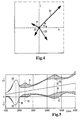
- Figure 4 are in a complex Vector diagram with the imaginary part on the Vertical and the real share on the horizontal the first harmonic 21, the second harmonic Harmonic 22, the third harmonic harmonic 23 and the fourth harmonic 24 is shown. It's out of here recognizable that in particular the fourth harmonic 24 has a significant proportion of engine noise.
- the pulsation volume flow is in the diagram according to FIG +/- V recorded over the engine speed rpm, here in particular the pulsation volume flow, the caused by the fourth harmonic 24 is between lines 30 and the pulsation volume flow, who the whole event including the hatched area between lines 31 is shown. It can also be seen here that the Vibrations only at a fixed engine speed Show zero position and that the zero position of the vibrations increases with increasing speed. You can do this various resonances indicated by dashed lines 32 occur which the vibration deflection when reaching certain frequencies increase several times can leave.
- the flap 5 at the output 14 of the control unit 10 deal with the aforementioned a number of boundary conditions, which is taken into account with a suitable control program can be.
- Closing and opening the flap 5 should take place with a suitable first frequency and the vibration ranges over half and a quarter Cross section of the intake tract 3 with multiples of this first Frequency.
- a suitable control with realistic Engine speeds can e.g. with a first frequency of 100 Hz for closing and opening, a second frequency of 200 Hz for the vibration range over half Cross section and a third frequency of 400 to 800 Hz for the range of motion over a quarter of the cross-section respectively.
Landscapes
- Engineering & Computer Science (AREA)
- Chemical & Material Sciences (AREA)
- Combustion & Propulsion (AREA)
- Mechanical Engineering (AREA)
- General Engineering & Computer Science (AREA)
- Characterised By The Charging Evacuation (AREA)
- Soundproofing, Sound Blocking, And Sound Damping (AREA)
- Exhaust Gas After Treatment (AREA)
- Exhaust Silencers (AREA)
Description
Claims (8)
- Verfahren zur Beeinflussung des Schalls im Ansaugtrakt eines Verbrennungsmotors, bei demdie einen Saugpuls verursachenden Betriebszustände im Ansaugtrakt (3) und/oder am Verbrennungsmotor (3) erfasst werden und der Schall durch eine Beeinflussung der akustischen Verhältnisse im Ansaugtrakt (3) vermindert wird, unddie Beeinflussung des Schalls durch einen zumindest teilweisen Verschluss des Strömungskanals im Ansaugtrakt (3) zu vorgegebenen, periodisch wiederkehrenden Zeiten erfolgt, in denen kein oder ein geringer Luftmassentransport im Strömungskanal stattfindet, wobeimit einem Steuerprogramm ein Steuersignal zur Amplituden- und Phasensteuerung hinsichtlich des Verschließens und Öffnens des Durchströmungsquerschnitts des Ansaugtraktes (3) zumindest in Abhängigkeit von der Drehzahl des Verbrennungsmotors (1) erzeugt wird, dadurch gekennzeichnet, dassdas Verschließen und Öffnen mit einer geeigneten ersten Frequenz erfolgt und die Schwingweiten über den halben und den viertel Durchströmungsquerschnitt des Ansaugtraktes (3) mit Vielfachen dieser ersten Frequenz erfolgt.
- Verfahren nach Anspruch 1, dadurch gekennzeichnet, dassdas Steuerprogramm zur Amplituden- und Phasensteuerung hinsichtlich des Verschließens und Öffnens des Durchströmungsquerschnitts eine Verschiebung der Nullage der Schwingungen des Luftmassenstroms mit der Änderung der Drehzahl des Verbrennungsmotors (1) berücksichtigt.
- Verfahren nach Anspruch 1 oder 2, dadurch gekennzeichnet, dassdas Steuerprogramm das Verschließen und Öffnen des Durchströmungsquerschnitts derart steuert, dass eine erste Frequenz von 100 Hz zum Verschließen und Öffnen des Durchströmungsquerschnitts, eine zweite Frequenz von 200 Hz für die Schwingweite über den halben Querschnitt und eine dritte Frequenz von 400 bis 800 Hz für die Schwingweite über ein Viertel des Querschnitts erzeugt wird.
- Verfahren nach einem der vorhergehenden Ansprüche, dadurch gekennzeichnet, dassdie Beeinflussung des Schalls derart durchgeführt wird, dass die Daten des Verbrennungsmotors und des Ansaugtraktes unter Zugrundelegung eines zuvor ermittelten akustischen Modells für die schallführenden Teile auswertet werden und damit das Steuerprogramm ausgeführt wird.
- Vorrichtung zur Durchführung des Verfahrens nach Anspruch 1, dadurch gekennzeichnet, dassim Ansaugtrakt (3) ein in Amplitude und Phasenlage steuerbares, Stellglied (5) vorhanden ist, mit dem der Luftmassenstrom (9) beeinflussbar ist, wobei die einen Saugpuls verursachenden Betriebszustände im Ansaugtrakt (3) und/oder am Verbrennungsmotor (3) erfasst werden und der Schall durch eine Beeinflussung der akustischen Verhältnisse im Ansaugtrakt (3) vermindert wird, und wobei ein Steuerprogramm vorgesehen ist zur Erzeugung eines Steuersignals zur Amplituden- und Phasensteuerung hinsichtlich des Verschließens und des Öffnens des Durchströmungsquerschnittes des Ansaugtrakts (3) in Abhängigkeit von der Drehzahl des Verbrennungsmotors (1), wobei das Verschließen und Öffnen mit einer geeigneten ersten Frequenz erfolgt und die Schwingweiten über den halben und den viertel Durchströmungsquerschnitt des Ansaugtraktes (3) mit Vielfachen dieser ersten Frequenz erfolgt.
- Vorrichtung nach Anspruch 5, dadurch gekennzeichnet, dassdas Stellglied eine ein- oder mehrachsige Klappe (5) ist, die durch Rotation um mindestens eine Achse zwischen einem Verschluss und einer Freigabe des Durchströmungsquerschnitts steuerbar ist.
- Vorrichtung nach Anspruch 5, dadurch gekennzeichnet, dassdas Stellglied ein quer zur Strömungsrichtung bewegter Kolben, Schieber oder ähnliche Vorrichtung ist, die durch eine Bewegung in Hubrichtung zwischen einem Verschluss und einer Freigabe des Durchströmungsquerschnitts steuerbar ist.
- Vorrichtung nach Anspruch 5, dadurch gekennzeichnet, dassdas Stellglied eine Irisblende ist, die durch eine entsprechende Führung der Blendlamellen zwischen einem Verschluss und einer Freigabe des Durchströmungsquerschnitts steuerbar ist.
Applications Claiming Priority (2)
| Application Number | Priority Date | Filing Date | Title |
|---|---|---|---|
| DE19955900 | 1999-11-20 | ||
| DE19955900 | 1999-11-20 |
Publications (3)
| Publication Number | Publication Date |
|---|---|
| EP1101929A2 EP1101929A2 (de) | 2001-05-23 |
| EP1101929A3 EP1101929A3 (de) | 2002-07-10 |
| EP1101929B1 true EP1101929B1 (de) | 2004-05-26 |
Family
ID=7929753
Family Applications (1)
| Application Number | Title | Priority Date | Filing Date |
|---|---|---|---|
| EP00124963A Expired - Lifetime EP1101929B1 (de) | 1999-11-20 | 2000-11-16 | Verfahren und Vorrichtung zur Beeinflussung des Schalls im Ansaugtrakt eines Verbrennungsmotors |
Country Status (3)
| Country | Link |
|---|---|
| EP (1) | EP1101929B1 (de) |
| AT (1) | ATE267955T1 (de) |
| DE (2) | DE10055399A1 (de) |
Families Citing this family (8)
| Publication number | Priority date | Publication date | Assignee | Title |
|---|---|---|---|---|
| DE10044604B4 (de) * | 2000-09-09 | 2004-07-15 | Heinrich Gillet Gmbh | Verfahren zum Erzeugen eines an harmonischen Frequenzen reichen, sportlich klingenden Ansaug- und/oder Auspuffgeräusches bei Viertaktmotoren |
| DE20207299U1 (de) | 2002-05-10 | 2002-09-12 | Filterwerk Mann + Hummel GmbH, 71638 Ludwigsburg | Vorrichtung zur Beeinflussung des Schalls im Ansaugtrakt eines Verbrennungsmotors |
| DE20207300U1 (de) | 2002-05-10 | 2002-09-05 | Filterwerk Mann + Hummel GmbH, 71638 Ludwigsburg | Vorrichtung zur Beeinflussung des Schalls im Ansaugtrakt eines Verbrennungsmotors |
| DE10248607A1 (de) * | 2002-10-17 | 2004-05-06 | Deutsche Montan Technologie Gmbh | Verfahren zum Erzeugen eines Frequenzspektrums in einer Auspuffrohrleitung einer Hubkolbenmaschine |
| DE10248609A1 (de) * | 2002-10-17 | 2004-05-06 | Deutsche Montan Technologie Gmbh | Verfahren zur Beeinflussung des Vebrennungsvorganges einer Brennkraftmaschine |
| DE10251117A1 (de) * | 2002-11-02 | 2004-05-19 | Deutsche Montan Technologie Gmbh | Vorrrichtung zum Erzeugen eines Frequenzspektrums in einer Rohrleitung |
| DE102015013696B4 (de) | 2015-10-22 | 2018-04-19 | KÖTTER Consulting Engineers GmbH & Co. KG | Pulsationsdämpfereinheit mit dynamisch veränderlichem Verlustbeiwert |
| DE102020200118A1 (de) * | 2020-01-08 | 2021-07-08 | Volkswagen Aktiengesellschaft | Verfahren zur Detektion eines kritischen Zustands bei einem Kältemittelkreislauf eines Fahrzeuges |
Family Cites Families (5)
| Publication number | Priority date | Publication date | Assignee | Title |
|---|---|---|---|---|
| DE3613828A1 (de) * | 1986-04-24 | 1987-10-29 | Bayerische Motoren Werke Ag | Ansauggeraeuschdaempfer, insbesondere fuer brennkraftmaschinen |
| GB8928052D0 (en) * | 1989-12-12 | 1990-02-14 | Lotus Group Plc | Control of pressure vibrations in ducts |
| FR2693505B1 (fr) * | 1992-07-07 | 1994-09-09 | Centre Ntl Recherche Scient | Ligne d'admission ou d'échappement pour machine alternative. |
| JPH08246969A (ja) | 1995-03-15 | 1996-09-24 | Unisia Jecs Corp | 自動車用アクティブ騒音制御装置 |
| DE19752142A1 (de) | 1997-11-25 | 1999-05-27 | Mann & Hummel Filter | Verfahren und Vorrichtung zur Bestimmung der akustischen Eigenschaften eines schallführenden Kanals |
-
2000
- 2000-11-09 DE DE10055399A patent/DE10055399A1/de not_active Withdrawn
- 2000-11-16 DE DE50006582T patent/DE50006582D1/de not_active Expired - Fee Related
- 2000-11-16 AT AT00124963T patent/ATE267955T1/de not_active IP Right Cessation
- 2000-11-16 EP EP00124963A patent/EP1101929B1/de not_active Expired - Lifetime
Also Published As
| Publication number | Publication date |
|---|---|
| EP1101929A3 (de) | 2002-07-10 |
| ATE267955T1 (de) | 2004-06-15 |
| EP1101929A2 (de) | 2001-05-23 |
| DE50006582D1 (de) | 2004-07-01 |
| DE10055399A1 (de) | 2001-05-23 |
Similar Documents
| Publication | Publication Date | Title |
|---|---|---|
| DE102004007717B4 (de) | Helmholtz-Resonator | |
| DE69319783T2 (de) | Geräuschminderungssystem | |
| DE69422033T2 (de) | Hybrides analog/digital schwingungsunterdrückungssystem | |
| DE69223238T2 (de) | Verfahren und Vorrichtung zur Dämpfung akustischer Schwingungen in einem Medium | |
| EP1101929B1 (de) | Verfahren und Vorrichtung zur Beeinflussung des Schalls im Ansaugtrakt eines Verbrennungsmotors | |
| DE112006002343B4 (de) | Verfahren und Vorrichtung zur Regelung des Schalls eines Motors durch Schaltfrequenzanalyse | |
| EP1221158A1 (de) | Verfahren und vorrichtung zur aktiven beeinflussung des ansauggeräusches einer brennkraftmaschine | |
| DE102016100542A1 (de) | Verfahren zur Erzeugung eines Ansteuerungssignals für einen in einem Motorfahrzeug angeordneten Lautsprecher sowie Abgasanlage für einen Motor und Soundsystem für eine Fahrgastzelle | |
| DE102015222587A1 (de) | Adaptiver Schwingungsdämpfer | |
| WO1997046797A1 (de) | Luftdurchströmungsvorrichtung | |
| EP1152132B1 (de) | Leitungssystem mit elektromechanischem Wandler zur Erzeugung eines Korrekturgeräusches | |
| DE102017126761A1 (de) | Vakuumbetätigter mehrfrequenz-viertelwellenresonator für einen verbrennungsmotor | |
| EP0242797B1 (de) | Ansauggeräuschdämpfer, insbesondere für Brennkraftmaschinen | |
| DE19548039B4 (de) | Vibrationsisoliervorrichtung | |
| EP0805431B1 (de) | Verfahren und Vorrichtung zur aktiven Schallreduzierung von Gasstromen | |
| DE4108734A1 (de) | Verfahren und anordnung zur daempfung von ruckelschwingungen eines kraftfahrzeugs | |
| EP1233161A2 (de) | Ansaugvorrichtung für eine Brennkraftmaschine und Verfahren zu deren Betrieb | |
| DE10062107C1 (de) | Aktorregelung | |
| DE102010040622A1 (de) | Verfahren zum Betreiben einer direkteinspritzenden Brennkraftmaschine und direkteinspritzende Brennkraftmaschine | |
| DE4113248C2 (de) | ||
| DE102014213253B4 (de) | Verfahren zum Betrieb eines Nockenwellenverstellers und Regelvorrichtung für einen Nockenwellenversteller | |
| DE4446080B4 (de) | Schallabsorptionssystem für Kraftfahrzeuge | |
| DE10226205B4 (de) | Vorrichtung zur Beeinflussung des Schalls im Ansaugtrakt eines Verbrenungsmotors | |
| EP2073195A1 (de) | Verfahren und Vorrichtung zum Unterdrücken, zumindest aber zum Verringern von störenden Vibrationen in einem motorbetriebenen Gerät, insbesondere einem Hausgerät | |
| DE19849036C2 (de) | Verfahren und Einrichtung zum Regeln eines elektromechanischen Stellantriebs |
Legal Events
| Date | Code | Title | Description |
|---|---|---|---|
| PUAI | Public reference made under article 153(3) epc to a published international application that has entered the european phase |
Free format text: ORIGINAL CODE: 0009012 |
|
| AK | Designated contracting states |
Kind code of ref document: A2 Designated state(s): AT BE CH CY DE DK ES FI FR GB GR IE IT LI LU MC NL PT SE TR |
|
| AX | Request for extension of the european patent |
Free format text: AL;LT;LV;MK;RO;SI |
|
| PUAL | Search report despatched |
Free format text: ORIGINAL CODE: 0009013 |
|
| AK | Designated contracting states |
Kind code of ref document: A3 Designated state(s): AT BE CH CY DE DK ES FI FR GB GR IE IT LI LU MC NL PT SE TR |
|
| AX | Request for extension of the european patent |
Free format text: AL;LT;LV;MK;RO;SI |
|
| 17P | Request for examination filed |
Effective date: 20021011 |
|
| AKX | Designation fees paid |
Designated state(s): AT BE CH CY DE DK ES FI FR GB GR IE IT LI LU MC NL PT SE TR |
|
| GRAP | Despatch of communication of intention to grant a patent |
Free format text: ORIGINAL CODE: EPIDOSNIGR1 |
|
| RAP1 | Party data changed (applicant data changed or rights of an application transferred) |
Owner name: MANN + HUMMEL GMBH |
|
| GRAS | Grant fee paid |
Free format text: ORIGINAL CODE: EPIDOSNIGR3 |
|
| GRAA | (expected) grant |
Free format text: ORIGINAL CODE: 0009210 |
|
| AK | Designated contracting states |
Kind code of ref document: B1 Designated state(s): AT BE CH CY DE DK ES FI FR GB GR IE IT LI LU MC NL PT SE TR |
|
| PG25 | Lapsed in a contracting state [announced via postgrant information from national office to epo] |
Ref country code: IT Free format text: LAPSE BECAUSE OF FAILURE TO SUBMIT A TRANSLATION OF THE DESCRIPTION OR TO PAY THE FEE WITHIN THE PRESCRIBED TIME-LIMIT;WARNING: LAPSES OF ITALIAN PATENTS WITH EFFECTIVE DATE BEFORE 2007 MAY HAVE OCCURRED AT ANY TIME BEFORE 2007. THE CORRECT EFFECTIVE DATE MAY BE DIFFERENT FROM THE ONE RECORDED. Effective date: 20040526 Ref country code: CY Free format text: LAPSE BECAUSE OF FAILURE TO SUBMIT A TRANSLATION OF THE DESCRIPTION OR TO PAY THE FEE WITHIN THE PRESCRIBED TIME-LIMIT Effective date: 20040526 Ref country code: IE Free format text: LAPSE BECAUSE OF FAILURE TO SUBMIT A TRANSLATION OF THE DESCRIPTION OR TO PAY THE FEE WITHIN THE PRESCRIBED TIME-LIMIT Effective date: 20040526 Ref country code: TR Free format text: LAPSE BECAUSE OF FAILURE TO SUBMIT A TRANSLATION OF THE DESCRIPTION OR TO PAY THE FEE WITHIN THE PRESCRIBED TIME-LIMIT Effective date: 20040526 Ref country code: NL Free format text: LAPSE BECAUSE OF FAILURE TO SUBMIT A TRANSLATION OF THE DESCRIPTION OR TO PAY THE FEE WITHIN THE PRESCRIBED TIME-LIMIT Effective date: 20040526 Ref country code: FI Free format text: LAPSE BECAUSE OF FAILURE TO SUBMIT A TRANSLATION OF THE DESCRIPTION OR TO PAY THE FEE WITHIN THE PRESCRIBED TIME-LIMIT Effective date: 20040526 |
|
| REG | Reference to a national code |
Ref country code: GB Ref legal event code: FG4D Free format text: NOT ENGLISH |
|
| REG | Reference to a national code |
Ref country code: CH Ref legal event code: EP |
|
| REG | Reference to a national code |
Ref country code: IE Ref legal event code: FG4D Free format text: GERMAN |
|
| REF | Corresponds to: |
Ref document number: 50006582 Country of ref document: DE Date of ref document: 20040701 Kind code of ref document: P |
|
| PG25 | Lapsed in a contracting state [announced via postgrant information from national office to epo] |
Ref country code: GR Free format text: LAPSE BECAUSE OF FAILURE TO SUBMIT A TRANSLATION OF THE DESCRIPTION OR TO PAY THE FEE WITHIN THE PRESCRIBED TIME-LIMIT Effective date: 20040826 Ref country code: SE Free format text: LAPSE BECAUSE OF FAILURE TO SUBMIT A TRANSLATION OF THE DESCRIPTION OR TO PAY THE FEE WITHIN THE PRESCRIBED TIME-LIMIT Effective date: 20040826 Ref country code: DK Free format text: LAPSE BECAUSE OF FAILURE TO SUBMIT A TRANSLATION OF THE DESCRIPTION OR TO PAY THE FEE WITHIN THE PRESCRIBED TIME-LIMIT Effective date: 20040826 |
|
| PG25 | Lapsed in a contracting state [announced via postgrant information from national office to epo] |
Ref country code: ES Free format text: LAPSE BECAUSE OF FAILURE TO SUBMIT A TRANSLATION OF THE DESCRIPTION OR TO PAY THE FEE WITHIN THE PRESCRIBED TIME-LIMIT Effective date: 20040906 |
|
| GBT | Gb: translation of ep patent filed (gb section 77(6)(a)/1977) |
Effective date: 20040901 |
|
| PG25 | Lapsed in a contracting state [announced via postgrant information from national office to epo] |
Ref country code: AT Free format text: LAPSE BECAUSE OF NON-PAYMENT OF DUE FEES Effective date: 20041116 Ref country code: LU Free format text: LAPSE BECAUSE OF NON-PAYMENT OF DUE FEES Effective date: 20041116 |
|
| PG25 | Lapsed in a contracting state [announced via postgrant information from national office to epo] |
Ref country code: BE Free format text: LAPSE BECAUSE OF NON-PAYMENT OF DUE FEES Effective date: 20041130 Ref country code: MC Free format text: LAPSE BECAUSE OF NON-PAYMENT OF DUE FEES Effective date: 20041130 Ref country code: LI Free format text: LAPSE BECAUSE OF NON-PAYMENT OF DUE FEES Effective date: 20041130 Ref country code: CH Free format text: LAPSE BECAUSE OF NON-PAYMENT OF DUE FEES Effective date: 20041130 |
|
| NLV1 | Nl: lapsed or annulled due to failure to fulfill the requirements of art. 29p and 29m of the patents act | ||
| REG | Reference to a national code |
Ref country code: IE Ref legal event code: FD4D |
|
| ET | Fr: translation filed | ||
| PLBE | No opposition filed within time limit |
Free format text: ORIGINAL CODE: 0009261 |
|
| STAA | Information on the status of an ep patent application or granted ep patent |
Free format text: STATUS: NO OPPOSITION FILED WITHIN TIME LIMIT |
|
| 26N | No opposition filed |
Effective date: 20050301 |
|
| BERE | Be: lapsed |
Owner name: *MANN + HUMMEL G.M.B.H. Effective date: 20041130 |
|
| REG | Reference to a national code |
Ref country code: CH Ref legal event code: PL |
|
| PGFP | Annual fee paid to national office [announced via postgrant information from national office to epo] |
Ref country code: DE Payment date: 20051110 Year of fee payment: 6 Ref country code: FR Payment date: 20051110 Year of fee payment: 6 |
|
| PGFP | Annual fee paid to national office [announced via postgrant information from national office to epo] |
Ref country code: GB Payment date: 20051121 Year of fee payment: 6 |
|
| PG25 | Lapsed in a contracting state [announced via postgrant information from national office to epo] |
Ref country code: DE Free format text: LAPSE BECAUSE OF NON-PAYMENT OF DUE FEES Effective date: 20070601 |
|
| GBPC | Gb: european patent ceased through non-payment of renewal fee |
Effective date: 20061116 |
|
| REG | Reference to a national code |
Ref country code: FR Ref legal event code: ST Effective date: 20070731 |
|
| PG25 | Lapsed in a contracting state [announced via postgrant information from national office to epo] |
Ref country code: GB Free format text: LAPSE BECAUSE OF NON-PAYMENT OF DUE FEES Effective date: 20061116 |
|
| BERE | Be: lapsed |
Owner name: *MANN + HUMMEL G.M.B.H. Effective date: 20041130 |
|
| PG25 | Lapsed in a contracting state [announced via postgrant information from national office to epo] |
Ref country code: PT Free format text: LAPSE BECAUSE OF NON-PAYMENT OF DUE FEES Effective date: 20041026 |
|
| PG25 | Lapsed in a contracting state [announced via postgrant information from national office to epo] |
Ref country code: FR Free format text: LAPSE BECAUSE OF NON-PAYMENT OF DUE FEES Effective date: 20061130 |