EP1102130A2 - Dispositif pour rendre étanche un palier d'arbre dans des unités de développement de machines de reproduction électrographique - Google Patents
Dispositif pour rendre étanche un palier d'arbre dans des unités de développement de machines de reproduction électrographique Download PDFInfo
- Publication number
- EP1102130A2 EP1102130A2 EP00124298A EP00124298A EP1102130A2 EP 1102130 A2 EP1102130 A2 EP 1102130A2 EP 00124298 A EP00124298 A EP 00124298A EP 00124298 A EP00124298 A EP 00124298A EP 1102130 A2 EP1102130 A2 EP 1102130A2
- Authority
- EP
- European Patent Office
- Prior art keywords
- developer
- housing
- sealing
- developer material
- bearing
- Prior art date
- Legal status (The legal status is an assumption and is not a legal conclusion. Google has not performed a legal analysis and makes no representation as to the accuracy of the status listed.)
- Withdrawn
Links
- 238000007789 sealing Methods 0.000 title claims abstract description 60
- 239000000463 material Substances 0.000 claims abstract description 50
- 230000020169 heat generation Effects 0.000 claims description 2
- 239000002245 particle Substances 0.000 description 18
- 230000032258 transport Effects 0.000 description 12
- 239000004810 polytetrafluoroethylene Substances 0.000 description 2
- 229920001343 polytetrafluoroethylene Polymers 0.000 description 2
- 230000002028 premature Effects 0.000 description 2
- 125000006850 spacer group Chemical group 0.000 description 2
- OKTJSMMVPCPJKN-UHFFFAOYSA-N Carbon Chemical compound [C] OKTJSMMVPCPJKN-UHFFFAOYSA-N 0.000 description 1
- 230000005684 electric field Effects 0.000 description 1
- 239000011888 foil Substances 0.000 description 1
- 229910002804 graphite Inorganic materials 0.000 description 1
- 239000010439 graphite Substances 0.000 description 1
- 230000005484 gravity Effects 0.000 description 1
- 239000004519 grease Substances 0.000 description 1
- 230000035515 penetration Effects 0.000 description 1
- 230000002093 peripheral effect Effects 0.000 description 1
- 229920001296 polysiloxane Polymers 0.000 description 1
- 230000001850 reproductive effect Effects 0.000 description 1
- 230000000717 retained effect Effects 0.000 description 1
Images


Classifications
-
- G—PHYSICS
- G03—PHOTOGRAPHY; CINEMATOGRAPHY; ANALOGOUS TECHNIQUES USING WAVES OTHER THAN OPTICAL WAVES; ELECTROGRAPHY; HOLOGRAPHY
- G03G—ELECTROGRAPHY; ELECTROPHOTOGRAPHY; MAGNETOGRAPHY
- G03G15/00—Apparatus for electrographic processes using a charge pattern
- G03G15/06—Apparatus for electrographic processes using a charge pattern for developing
- G03G15/08—Apparatus for electrographic processes using a charge pattern for developing using a solid developer, e.g. powder developer
- G03G15/0896—Arrangements or disposition of the complete developer unit or parts thereof not provided for by groups G03G15/08 - G03G15/0894
- G03G15/0898—Arrangements or disposition of the complete developer unit or parts thereof not provided for by groups G03G15/08 - G03G15/0894 for preventing toner scattering during operation, e.g. seals
-
- G—PHYSICS
- G03—PHOTOGRAPHY; CINEMATOGRAPHY; ANALOGOUS TECHNIQUES USING WAVES OTHER THAN OPTICAL WAVES; ELECTROGRAPHY; HOLOGRAPHY
- G03G—ELECTROGRAPHY; ELECTROPHOTOGRAPHY; MAGNETOGRAPHY
- G03G15/00—Apparatus for electrographic processes using a charge pattern
- G03G15/06—Apparatus for electrographic processes using a charge pattern for developing
- G03G15/08—Apparatus for electrographic processes using a charge pattern for developing using a solid developer, e.g. powder developer
- G03G15/0822—Arrangements for preparing, mixing, supplying or dispensing developer
Definitions
- the present invention relates generally to a device for sealing Shaft bearings of a developer station in electrographic reproduction facilities.
- the dielectric carrier element In conventional, commercially available electrographic reproduction devices (e.g. Copiers, printers etc.) is a latent charge image on a uniformly charged, the charge image-storing photoconductor element with dielectric properties (in Hereinafter referred to as the dielectric carrier element).
- This latent Charge image attracts pigmented marking particles, which the image on the develop dielectric carrier element.
- a receiving element for. B. a sheet of paper, foil or other medium with the dielectric Carrier element brought into contact and an electric field applied so that by the marking particle developed image from the dielectric carrier element on the Receiving element is transmitted.
- the illustrated Recording element moved away from the dielectric carrier element and the image by heat and pressure on the receiving element fixed (melted), so that a permanent Picture arises.
- a widely used type of electrostatographic reproduction equipment Developer stations is the developer station with a magnetic brush, e.g. in the US 4,887,132.
- This includes a housing that has a variety of elements contains and forms a reservoir for the developer material.
- the Developer material can e.g. B. be designed as a two-component developer material, the magnetic carrier particle and smaller pigmented compared to this Contains marking particles.
- the developer station includes one in the reservoir arranged mixing device, for. B. a paddle wheel, a screw mixer or a Belt mixer, by means of which the carrier particles and the marking particles are stirred to triboelectrically charge the particles so that the marking particles on the Stick surface of the carrier particles.
- a transport device transports that Developer material from the reservoir into one generated by a variety of magnets Field, the magnets being arranged within a rotating sleeve.
- the sleeve is usually referred to as a toner roller. It is possible that the magnets rotate while the sleeve remains stationary, or that the sleeve with another Angular velocity as the magnets rotate.
- the rotating sleeve and the magnetic Fields cause the marking particles to come close to the latent charge image brought to the dielectric carrier element and applied to the charge image, so that this is developed.
- the drive shafts of the mixing device and the transport device in the Developer station of the electrographic reproduction device run through the Developer station and are in, in the side walls of the housing of the developer station arranged, stored bearings.
- the bearings are usually sealed protected. Due to the properties of the developer material, the well-known offer However, sealing arrangements do not provide complete protection for the bearings. Since the Particles of the developer material are tiny, the developer material can Seals penetrate into the bearings, causing premature wear of the Caused storage.
- the object of the present invention is to provide a device for sealing Shaft bearings in developer stations in electrographic reproduction facilities create the unwanted intrusion of developer material into the bearings in the developer station essentially prevented.
- a shaft has a plurality of Assigned sealing elements which in the direction of the longitudinal axis of the drive shaft Housing with the developer material increasingly towards the outside run and at least one of which is rotatable with the drive shaft, while the adjacent sealing elements are arranged stationary.
- This sealing arrangement according to the invention has proven to be very effective and Bearing life extended significantly.
- the sealing elements are made of one Material made with a low coefficient of friction, so that when the Sealing elements with respect to each other the friction and heat generation is reduced.
- the sealing elements are advantageously arranged like a labyrinth. Reduced here the developer material trapped in the labyrinthine seal assembly is the one of developer material entering the recess for the seal Pressure and thus forms another sealing element.
- seal assembly doesn't just protect against Pollution of the bearings serves, but also prevents bearing grease in the Housing of the developer station penetrates and contaminates the developer material.
- the developer station 10 with magnetic brush comprises a housing 12, the interconnected areas 12a-12c defines the chambers, including a lower region 12a, which as Storage container for developer material D is used.
- the developer material is for example, a two-component material made of magnetic carrier particles mixed with compared to these smaller, pigmented marking particles.
- the upper region 12b of the housing 12 comprises a toner roller 14 for applying the Marking particles on those formed on a dielectric carrier element 16 Charge pattern.
- the carrier element 16 moves along a path P which is on a Opening O in the upper housing section 12b passes.
- the toner roller 14 of the developer station 10 with a magnetic brush comprises a core 18 um a plurality of magnets 20 are arranged on the peripheral surface thereof.
- the core 18 is of a non-magnetic, substantially cylindrical shell 22 surrounded, the longitudinal axis of which is offset with respect to the longitudinal axis of the core 18.
- This offset arrangement causes a reduction in the field strength of the magnets 20 in that of the magnet 20 more distant area of the casing 22, so that Developer material in this area has a lower tendency to coat stick and get back into the reservoir instead.
- the core and / or the Sheathing can be fixed or rotatable in a known manner; the respective Arrangement only needs to ensure that the developer material is in the from the magnet 20 generated field and comes into contact with the dielectric carrier element 16.
- the toner roller 14 shown in FIG. 1 rotates the core 18 (with the magnet 20) in the Clockwise while the jacket 22 rotates counterclockwise.
- the Marking particles in the developer material are separated from that on the dielectric Carrier element 16 formed latent charge pattern attracted and go Adhesion with the charge pattern, whereby the pattern is developed.
- the developed pattern can then on an arcuate receiving element transferred and fixed by exposure to heat and / or pressure or else be fixed directly on the dielectric carrier element, so that the desired Reproduction of the picture arises.
- the developer material D in that formed by the housing portion 12a Storage container is stirred by a mixing device 24.
- the mixing arrangement 24 is z. B. formed as a band mixer, the spiral inner band 28a and spiral outer band 28b, which is connected via arms 30 to a shaft 32 are.
- the shaft 32 is, as will be explained in more detail below, with respect to the housing 12 rotatably supported about the longitudinal axis of the shaft.
- the slopes of bands 28a and 28b run in opposite directions so that when the belts rotate through the shaft 32 the developer material along the length of the mixer in opposite directions is moved and stirred. This creates a triboelectric charge, due to which adhesion of the marking particles to the carrier particles is brought about.
- the present invention can also be used for other types of Mixing devices, e.g. B. paddle wheels or a screw mixer can be used.
- the mixing device 24 also moves the developer material radially with respect to the Mixer, so that the material in the designated by reference numeral 12c Arrives housing section in which a transport device 34 is arranged.
- the Device 34 comprises a plurality of driving elements 40, which are connected to a shaft 42 arranged and rotatable with this. As explained in more detail below, the shaft 42 rotatably supported about its longitudinal axis with respect to the housing 12.
- the Driving elements 40 are used to transport the developer material into the Magnet 20 of the toner roller 14 generated field.
- the driving elements 40 can, for. B. as Troughs are formed when the shaft 42 rotates through the developer material be moved while absorbing developer material.
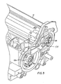
- Fig. 2 shows an actuating mechanism 50 which the drive shaft 32 of the band mixer of Mixer assembly 24 at a fixed horizontal distance from the inner wall of the Housing portion 12a of the housing 12 of the developer station and the shaft 32 in parallel to the shaft 42 of the transport device 34.
- the adjusting mechanism 50 is such formed that in each case one end of the shafts in a at the rear end 12d of the Housing 12 of the developer station arranged gear box 52 is mounted and that other end of the shafts in a bearing closure device 54 at the front end 12e of the Housing is mounted so that the gear box 52 for positioning the belt mixer serves the mixing device 24 and the troughs of the transport device 34.
- the bearing closure device 54 includes a Pair of bearing brackets 62a, 64a that support bearings 62 and 64, respectively. In camps 62 and 64, the ends of the shafts 32 and 42 are in turn supported.
- a spacer e.g.
- an arm 66 forms a stable connection of the bearing brackets 62a, 64a with each other.
- the spacer arm 66 is designed such that between the bearing brackets 62a, 64a there is a predetermined distance.
- the longitudinal axes of the shaft 32 are the Mixing device 24 and the shaft 42 of the transport device 34 in one predetermined distance from each other.
- Both the horizontal and the vertical distance between the bearings 62, 64 corresponds to the distance between the Drive the mixing device and the drive of the transport device in the Gearbox 52 so that the parallel arrangement of the shaft 32 of the mixing device and the shaft 42 of the transport device is retained.
- the present invention proposes a new seal assembly 70 in front.
- the new seal arrangement more effectively prevents damage to the Bearings of the drive shafts in a developer station from
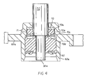
- the seal assembly 70 includes a variety of cooperating sealing elements which are in a recess in the housing of the Developer station are arranged like a labyrinth, and between the bearings and Developer material in the housing.
- the multitude of interacting Sealing elements form several arranged essentially in a row Sealing points and thus create a multiple seal. Some of the Sealing elements are arranged so that they rotate with the associated shaft, while other sealing elements are stationary.
- the Sealing arrangement 70 four sealing elements 70a-70d in the recess 71. It can a different number of sealing elements can also be provided, provided it the desired labyrinthine arrangement is created.
- the seal assembly 70 is in here Relation to that stored in the bearing 62 supported by the bearing bracket 62a Shaft 32 of the mixing device shown, but can of course also the other waves of Developer station 10 may be assigned, for. B. also the shaft 42 of the transport device.
- the first sealing element 70a is in the direction of the longitudinal axis of the associated shaft 32 considered closest to the chambers of the developer material D. Housing 12 of the developer station for the developer material is arranged. The remaining Sealing elements of the sealing arrangement 70 are along the longitudinal axis of the shaft 32 arranged at an increasing distance from the chambers for the developer material and form a labyrinthine arrangement.
- the first sealing element 70a has some clearance with respect to the shaft 32, so that it remains stationary in the bearing holder 62a when the shaft 32 rotates.
- the second Sealing element 70b is fixedly arranged on the shaft 32, so that it is in contact with this turns.
- the following third sealing element 70c again has a shaft 32 some leeway so that it remains stationary with respect to the bearing bracket 62a, and that fourth sealing element 70d is adjacent to the step on stepped portion 32a of FIG Shaft 32 and arranged on the bearing 62.
- the sealing elements 70a-70d can be made from any suitable Material be made, e.g. B. from silicone filled PTFE or from graphite filled PTFE. At least the sealing elements 70a, 70b and 70c are furthermore preferably made of a material with a low coefficient of friction (e.g. between 0.15 and 0.35), so that when the sealing elements rotate with respect each other the friction and heat build-up are reduced.
- the fourth sealing element 70d is provided to prevent it from possibly entering the first group of Sealing elements penetrated developer material in the vicinity of the inner Tread and the contact surface between the bearing 62 and the sealing element reached.
- the contact surface between the bearing 62 and the sealing element 70d forms the Area in which material can possibly enter the warehouse. That in the However, labyrinthine seal assembly 70 traps developer material reduced the developer material entering the recess for the seal applied pressure and thus forms a further sealing element.
Landscapes
- Physics & Mathematics (AREA)
- General Physics & Mathematics (AREA)
- Dry Development In Electrophotography (AREA)
Applications Claiming Priority (2)
| Application Number | Priority Date | Filing Date | Title |
|---|---|---|---|
| US444181 | 1999-11-19 | ||
| US09/444,181 US6295425B1 (en) | 1999-11-19 | 1999-11-19 | Seal assembly for electrographic reproduction apparatus development station |
Publications (2)
| Publication Number | Publication Date |
|---|---|
| EP1102130A2 true EP1102130A2 (fr) | 2001-05-23 |
| EP1102130A3 EP1102130A3 (fr) | 2002-05-02 |
Family
ID=23763837
Family Applications (1)
| Application Number | Title | Priority Date | Filing Date |
|---|---|---|---|
| EP00124298A Withdrawn EP1102130A3 (fr) | 1999-11-19 | 2000-11-15 | Dispositif pour rendre étanche un palier d'arbre dans des unités de développement de machines de reproduction électrographique |
Country Status (5)
| Country | Link |
|---|---|
| US (1) | US6295425B1 (fr) |
| EP (1) | EP1102130A3 (fr) |
| AU (1) | AU4708101A (fr) |
| DE (1) | DE10056721A1 (fr) |
| WO (1) | WO2001044876A2 (fr) |
Families Citing this family (10)
| Publication number | Priority date | Publication date | Assignee | Title |
|---|---|---|---|---|
| JP4124992B2 (ja) * | 2001-10-25 | 2008-07-23 | キヤノン株式会社 | トナー補給容器 |
| JP4011411B2 (ja) * | 2002-06-07 | 2007-11-21 | シャープ株式会社 | 印刷装置 |
| JP2004226695A (ja) * | 2003-01-23 | 2004-08-12 | Ricoh Co Ltd | 画像形成装置用現像装置の軸受シール構造、現像装置、及び画像形成装置 |
| DE102007009190B4 (de) * | 2007-02-26 | 2008-10-16 | OCé PRINTING SYSTEMS GMBH | Vorrichtung und Verfahren zur Abdichtung einer Welle gegen den Durchtritt eines Tonergemischs |
| JP6127881B2 (ja) * | 2013-09-30 | 2017-05-17 | ブラザー工業株式会社 | 現像装置 |
| JP6287348B2 (ja) * | 2014-03-04 | 2018-03-07 | コニカミノルタ株式会社 | トナー搬送装置および画像形成装置 |
| JP6528481B2 (ja) * | 2015-03-16 | 2019-06-12 | 富士ゼロックス株式会社 | 現像剤の収容体および画像形成装置 |
| JP6743469B2 (ja) * | 2015-04-23 | 2020-08-19 | 株式会社リコー | 粉体搬送装置、現像装置、プロセスカートリッジ、及び画像形成装置 |
| JP6631874B2 (ja) * | 2015-10-07 | 2020-01-15 | 株式会社リコー | 画像形成装置およびプロセスカートリッジ |
| JP2018081196A (ja) * | 2016-11-16 | 2018-05-24 | 株式会社リコー | 現像装置、プロセスカートリッジ、及び画像形成装置 |
Citations (1)
| Publication number | Priority date | Publication date | Assignee | Title |
|---|---|---|---|---|
| US4887132A (en) | 1984-04-06 | 1989-12-12 | Eastman Kodak Company | Electrographic development apparatus having a ribbon blender |
Family Cites Families (11)
| Publication number | Priority date | Publication date | Assignee | Title |
|---|---|---|---|---|
| JPS5857158A (ja) * | 1981-10-01 | 1983-04-05 | Canon Inc | 現像装置 |
| JPH02248974A (ja) * | 1989-03-22 | 1990-10-04 | Ricoh Co Ltd | 電子写真式記録装置の現像装置 |
| JPH0313977A (ja) * | 1989-06-13 | 1991-01-22 | Canon Inc | 現像装置 |
| JP2892456B2 (ja) * | 1989-08-04 | 1999-05-17 | キヤノン株式会社 | 現像装置 |
| JP2899079B2 (ja) * | 1990-07-10 | 1999-06-02 | キヤノン株式会社 | 現像装置 |
| US5450169A (en) * | 1994-06-23 | 1995-09-12 | Xerox Corporation | Multi-lobe magnetic seals |
| US5552864A (en) * | 1995-01-17 | 1996-09-03 | Xerox Corporation | Magnetic seal with tapered shunts |
| US5742875A (en) * | 1997-02-10 | 1998-04-21 | Xerox Corporation | Roll seal blade support for a xerographic development unit using magnetic toner |
| US5742876A (en) * | 1997-03-03 | 1998-04-21 | Xerox Corporation | Donor roll configuration of a xerographic development unit using magnetic toner |
| JP3448188B2 (ja) * | 1997-07-23 | 2003-09-16 | シャープ株式会社 | 現像剤処理装置 |
| JP3541919B2 (ja) * | 1997-08-26 | 2004-07-14 | 株式会社リコー | トナーカートリッジ |
-
1999
- 1999-11-19 US US09/444,181 patent/US6295425B1/en not_active Expired - Lifetime
-
2000
- 2000-11-14 AU AU47081/01A patent/AU4708101A/en not_active Abandoned
- 2000-11-14 WO PCT/US2000/042176 patent/WO2001044876A2/fr not_active Ceased
- 2000-11-15 DE DE10056721A patent/DE10056721A1/de not_active Withdrawn
- 2000-11-15 EP EP00124298A patent/EP1102130A3/fr not_active Withdrawn
Patent Citations (1)
| Publication number | Priority date | Publication date | Assignee | Title |
|---|---|---|---|---|
| US4887132A (en) | 1984-04-06 | 1989-12-12 | Eastman Kodak Company | Electrographic development apparatus having a ribbon blender |
Also Published As
| Publication number | Publication date |
|---|---|
| AU4708101A (en) | 2001-06-25 |
| WO2001044876A3 (fr) | 2002-02-07 |
| EP1102130A3 (fr) | 2002-05-02 |
| US6295425B1 (en) | 2001-09-25 |
| DE10056721A1 (de) | 2001-06-13 |
| WO2001044876A2 (fr) | 2001-06-21 |
Similar Documents
| Publication | Publication Date | Title |
|---|---|---|
| DE69711815T2 (de) | Dichtungsmechanismus und damit ausgerüsteter Behälter | |
| DE2545494C2 (de) | Magnetbürsten-Entwicklungseinrichtung | |
| DE69015446T2 (de) | Entwicklungsvorrichtungen für elektrofotografische Geräte. | |
| DE3031593C2 (de) | Entwicklungsvorrichtung für ein elektrophotographisches Kopiergerät | |
| DE69314889T2 (de) | In einem elektrophotographischen Gerät verwendeten Entwicklungs- und Reinigungsvorrichtung | |
| DE2161852C3 (de) | Vorrichtung zur Magnetbürstenentwicklung elektrostatischer latenter Bilder | |
| DE69612429T2 (de) | Mischer und mit dem Mischer ausgerüstete Tonerkartusche | |
| DE69725787T2 (de) | Rührer und Tonerkartusche mit Rührer | |
| DE3686164T2 (de) | Elektrographisches magnetbuerstenentwicklungsgeraet. | |
| DE3018906A1 (de) | Entwicklungsvorrichtung | |
| DE3225883C2 (de) | Entwicklungseinrichtung für ein Kopiergerät | |
| DE2816621B2 (de) | Dichtungsanordnung in einer Entwicklungsvorrichtung eines Kopiergerätes | |
| DE69824492T2 (de) | Entwicklerbehandlungsgerät mit Dichtungselement und Dichtungsschicht an der Halterung eines drehbaren Elements | |
| DE69627225T2 (de) | Magnetische Abdichtung für Entwicklungsgerät | |
| EP1102130A2 (fr) | Dispositif pour rendre étanche un palier d'arbre dans des unités de développement de machines de reproduction électrographique | |
| DE3223275C2 (fr) | ||
| DE10152892A1 (de) | Verfahren und Vorrichtung zur Reinigung von Trägerelementen in Druckern oder Kopierern unter Anwendung von Magnetfeldern | |
| DE19517329C2 (de) | Entwicklungsvorrichtung und Bilderzeugungsapparat unter Verwendung der Entwicklungsvorrichtung | |
| DE2730903A1 (de) | Entwicklerstation fuer ein elektrophotographisches kopiergeraet | |
| DE4427853A1 (de) | Vorrichtung zur Bilderzeugung | |
| DE3515000C2 (de) | Entwicklungsvorrichtung | |
| DE102007009190B4 (de) | Vorrichtung und Verfahren zur Abdichtung einer Welle gegen den Durchtritt eines Tonergemischs | |
| DE3228636A1 (de) | Entwicklungsvorrichtung mit magnetischer buerste | |
| DE69007768T2 (de) | Entwicklungsgerät für elektrostatische latente Bilder. | |
| DE69011323T2 (de) | Entwicklungsgerät mit zwei ineinander greifenden schaufelmischern. |
Legal Events
| Date | Code | Title | Description |
|---|---|---|---|
| PUAI | Public reference made under article 153(3) epc to a published international application that has entered the european phase |
Free format text: ORIGINAL CODE: 0009012 |
|
| AK | Designated contracting states |
Kind code of ref document: A2 Designated state(s): AT BE CH CY DE DK ES FI FR GB GR IE IT LI LU MC NL PT SE TR |
|
| AX | Request for extension of the european patent |
Free format text: AL;LT;LV;MK;RO;SI |
|
| PUAL | Search report despatched |
Free format text: ORIGINAL CODE: 0009013 |
|
| AK | Designated contracting states |
Kind code of ref document: A3 Designated state(s): AT BE CH CY DE DK ES FI FR GB GR IE IT LI LU MC NL PT SE TR |
|
| AX | Request for extension of the european patent |
Free format text: AL;LT;LV;MK;RO;SI |
|
| 17P | Request for examination filed |
Effective date: 20020405 |
|
| AKX | Designation fees paid |
Free format text: AT BE CH CY DE DK ES FI FR GB GR IE IT LI LU MC NL PT SE TR |
|
| STAA | Information on the status of an ep patent application or granted ep patent |
Free format text: STATUS: THE APPLICATION IS DEEMED TO BE WITHDRAWN |
|
| 18D | Application deemed to be withdrawn |
Effective date: 20030602 |