EP1103099B1 - Systeme und verfahren zum einstellen des verbrauchs und der leistung in einem funkempfänger- abwärtsumsetzer - Google Patents
Systeme und verfahren zum einstellen des verbrauchs und der leistung in einem funkempfänger- abwärtsumsetzer Download PDFInfo
- Publication number
- EP1103099B1 EP1103099B1 EP99930728A EP99930728A EP1103099B1 EP 1103099 B1 EP1103099 B1 EP 1103099B1 EP 99930728 A EP99930728 A EP 99930728A EP 99930728 A EP99930728 A EP 99930728A EP 1103099 B1 EP1103099 B1 EP 1103099B1
- Authority
- EP
- European Patent Office
- Prior art keywords
- gain
- low noise
- amplifier
- noise amplifier
- wireless device
- Prior art date
- Legal status (The legal status is an assumption and is not a legal conclusion. Google has not performed a legal analysis and makes no representation as to the accuracy of the status listed.)
- Expired - Lifetime
Links
Images
Classifications
-
- H—ELECTRICITY
- H04—ELECTRIC COMMUNICATION TECHNIQUE
- H04B—TRANSMISSION
- H04B1/00—Details of transmission systems, not covered by a single one of groups H04B3/00 - H04B13/00; Details of transmission systems not characterised by the medium used for transmission
- H04B1/06—Receivers
- H04B1/10—Means associated with receiver for limiting or suppressing noise or interference
-
- H—ELECTRICITY
- H03—ELECTRONIC CIRCUITRY
- H03G—CONTROL OF AMPLIFICATION
- H03G3/00—Gain control in amplifiers or frequency changers
- H03G3/20—Automatic control
- H03G3/30—Automatic control in amplifiers having semiconductor devices
- H03G3/3052—Automatic control in amplifiers having semiconductor devices in bandpass amplifiers (H.F. or I.F.) or in frequency-changers used in a (super)heterodyne receiver
- H03G3/3068—Circuits generating control signals for both R.F. and I.F. stages
-
- H—ELECTRICITY
- H03—ELECTRONIC CIRCUITRY
- H03G—CONTROL OF AMPLIFICATION
- H03G1/00—Details of arrangements for controlling amplification
- H03G1/0005—Circuits characterised by the type of controlling devices operated by a controlling current or voltage signal
- H03G1/0088—Circuits characterised by the type of controlling devices operated by a controlling current or voltage signal using discontinuously variable devices, e.g. switch-operated
-
- H—ELECTRICITY
- H03—ELECTRONIC CIRCUITRY
- H03F—AMPLIFIERS
- H03F2203/00—Indexing scheme relating to amplifiers with only discharge tubes or only semiconductor devices as amplifying elements covered by H03F3/00
- H03F2203/72—Indexing scheme relating to gated amplifiers, i.e. amplifiers which are rendered operative or inoperative by means of a control signal
- H03F2203/7239—Indexing scheme relating to gated amplifiers, i.e. amplifiers which are rendered operative or inoperative by means of a control signal the gated amplifier being switched on or off by putting into parallel or not, by choosing between amplifiers and shunting lines by one or more switch(es)
Definitions
- the present invention relates to receiver down converters and more particularly to receiver down converters for use in radiotelephones and radiotelephone equipment.
- CDMA Code Division Multiple Access
- the linearity of the low noise amplifier may be critical to meeting the requirements of CDMA.
- increasing the third order intercept point to increase the linearity of the amplifier generally requires an increase in the current drawn by the amplifier.
- the requirements of CDMA may directly conflict with the goal of low power consumption.
- the RF Micro Devices RF9906 down converter includes adjustable mixer gain which allows for high gain to overcome the higher filter loss of CDMA mode and a low gain for use in AMPS/DAMPS mode.
- the RF9986 device of RF Micro Devices allows for strong signal conditions in CDMA mode by having a switchable third order intercept point which may be increased by 10db by connecting Vcc to the IP3 pin of the device which causes the LNA current consumption to increase by 10 mA. While these devices allow the wireless telephone to meet the various requirements of the modes of operation of the wireless telephone, there continues to be a need to reduce the down converter's power requirements while still meeting the operational requirements of the wireless telephone.
- United States Patent No. 5,722,061 to Hutchison, IV et al. describes a method for adjusting the gain of a receive circuit to improve the receiver's immunity to interference.
- a low noise amplifier is enabled or disabled based on received signal strength.
- a further object of the present invention is to provide a down converter capable of handling strong signal conditions.
- Still another object of the present invention is to allow an increase in the battery life to radiotelephones.
- Another object of the present invention is to provide a down converter with reduced power consumption in multiple modes of operation of a radiotelephone.
- the performance of the down converter may be adjusted to the operating conditions of the telephone. Furthermore, the gains and third order intercept point may be adjusted to reduce the power consumption of the down converter. Thus, as the signal strength increases the performance of the down converter may be maintained while reducing the power required by the down converter. The total power required to operate the radiotelephone may be decreased and battery life correspondingly increased.
- the gains of the low noise amplifier and mixer amplifier of the down converter may be set by bypassing the low noise amplifier.
- the gains are selected between two gain levels for the amplifiers.
- the receiver of the wireless device may be disabled if the wireless device is in sleep mode.
- the received signal strength may be between about - 94 dBm and about -60 dBm.
- the present invention can allow the down converter to meet the performance criteria of CDMA while still conserving power.
- the receiver of the radiotelephone is disabled if the radiotelephone is in sleep mode.
- the third order intercept point of the low noise amplifier may be set to a low third order intercept point, the gain of the low noise amplifier set to a high gain and the gain of the mixer amplifier set to a low gain if the received signal strength is less than a first predefined signal strength threshold.
- the third order intercept of the low noise amplifier may be set to a low third order intercept point, the gain of the low noise amplifier set to a high gain and the gain of the mixer amplifier set to a low gain if the received signal strength is greater than the first predefined signal strength threshold an less than a second predefined signal strength threshold.
- the gain of the low noise amplifier may also be set to a low gain and the gain of the mixer amplifier set to a low gain if the received signal strength is greater than the second predefined signal strength threshold.
- the operation of a receiver of a radiotelephone so as to reduce the power consumption of the receiver by determining the received signal strength of a signal received by the radiotelephone and controlling the power consumption of a down converter of the receiver of the radiotelephone based upon the determined received signal strength.
- This determination may include determining if the received signal strength is above a first threshold value, if the received signal strength is between the first threshold value and a second threshold value and if the received signal strength is above the second threshold value.
- the gain of the low noise amplifier may then be set to a low gain and the gain of the mixer amplifier to a low gain if the signal strength is above the second threshold value, the gain of a low noise amplifier of the down converter set to a high gain and the gain of a mixer amplifier of the down converter set to a low gain if the received signal strength is between the first threshold value and the second threshold value and the gain of a low noise amplifier of the down converter set to a high gain and the gain of a mixer amplifier of the down converter set to a high gain if the received signal strength is below the first threshold value.
- the first threshold value is about -94 dBm
- the second threshold value is about -60 dBm.
- the power consumption of the down converter may be reduced without sacrificing performance.
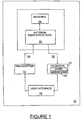
- radiotelephone 10 which includes a down converter 15 according to the present invention is depicted in the block diagram of Figure 1.
- radiotelephone 10 typically includes a transmitter 12, a receiver 14, a user interface 16 and an antenna system 18.
- the antenna system 18 may include an antenna feed structure 22 and an antenna 20.
- transmitter 12 converts the information which is to be transmitted by radiotelephone 10 into an electromagnetic signal suitable for radio communications.
- Receiver 14 demodulates electromagnetic signals which are received by radiotelephone 10 so as to provide the information contained in the signals to user interface 16 in a format which is understandable to the user.
- transmitters 12, receivers 14, user interfaces 16 e.g., microphones, keypads, rotary dials
- user interfaces 16 e.g., microphones, keypads, rotary dials
- radiotelephone 10 The design of radiotelephone 10 is well known to those of skill in the art and will not be further described herein.
- the present invention relates to the down converter 15 incorporated in receiver 14.
- the radiotelephone 10 includes as part of the receiver 14 a down converter 15.
- a radiotelephone incorporating the present invention also preferably includes circuitry and programming for measuring the signal strength received by the radiotelephone.
- Such circuitry and programming are well known to those of skill in the art and, therefore, will not be described in detail herein.
- it is preferable that such circuitry also contribute to the control of the output power of the transmitter portion of the radiotelephone.
- the output power of the transmitter 12 is preferably controlled, at least in part, by the received signal strength such that when the received signal strength is low the output power of the transmitter 12 is high and when the received signal strength is high the output power of the transmitter 12 is reduced.
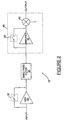
- a down converter 15 of the present invention utilizes information about the signal conditions and operational state of the radiotelephone to control the operation of the down converter 15 to reduce power consumption. Such control may be accomplished by selectively changing the linearity of an amplifier or amplifiers by changing the third order intercept of an amplifier or amplifiers in the down converter 15, by adjusting the gain of an amplifier or amplifiers in the down converter 15 or by selectively bypassing portions of the down converter 15.
- One embodiment of a down converter 15 which allows for such control is illustrated in Figure 2.
- the down converter 15 preferably includes a low noise amplifier (LNA) 30 which may receive and amplify the incoming signal.
- LNA low noise amplifier
- a switch 32 allows the LNA 30 to be bypassed.
- any number of switching devices may be utilized to bypass the LNA 30 such as a transistor, relay or other such switching devices known to those of skill in the art.
- the LNA 30 may be disabled so that it draws no power. Accordingly, bypassing LNA 30 may reduce the total power requirements of the radiotelephone 10.
- the output of the LNA 30 or the switch 32 is provided to an interstage filter, such as a band pass filter 34 and the output of the filter 34 provided to a variable gain mixer 46.
- the variable gain mixer 46 is illustrated as having an amplifier component 38 and a mixer component 40.
- the amplifier 38 of the variable gain mixer 46 may also be bypassed by a switch 42. By bypassing amplifier 38, the amplifier may be disabled so that it does not add to the power requirements of radiotelephone 10.
- Amplifiers 30 and 38 may be variable gain amplifiers and amplifier 30 may have an adjustable third order intercept point. Alternatively, fixed gain amplifiers may be utilized and the amplifier bypassed as described herein to provide two gain settings including a high gain when the amplifier is incorporated in the down converter and a low or no gain when the amplifier is bypassed.
- Amplifiers which provide an adjustable third order intercept point or variable gain include, for example, the PCS Low Noise Amplifier/Mixer RF9986 and the CDMA/FM Low Noise Amplifier/Mixer RF9906 of RF Micro Devices of Greensboro, North Carolina.
- While these devices may allow for variable gain or variable intercept points, there is no indication of how these devices may be intelligently controlled to provide the optimum tradeoff between power consumption and signal handling over the operating range of the radiotelephone 10.
- the gain and third order intercept point the power requirements of the amplifiers may be adjusted.
- the gain of the amplifiers 30 and 38 the power required by these amplifiers may be reduced.
- the present invention is described as bypassing amplifiers 30 and 38 with a switch, as will be appreciated by those of skill in the art, other methods of allowing a signal through the amplifier without requiring the amplifier to be active may be utilized while still benefiting from the teachings of the present invention.
- the present invention is not limited to two amplifier systems but may be utilized in systems having any number of amplifiers including single amplifier systems such as systems without an amplifier 38 in the mixer 46.
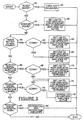
- FIG. 3 is a flowchart illustrating the operation of a down converter utilizing the present invention.
- each block of the flowchart illustration, and combinations of blocks in the flowchart illustration can be implemented by computer program instructions.
- These program instructions may be provided to a processor to produce a machine, such that the instructions which execute on the processor create means for implementing the functions.specified in the flowchart block or blocks.
- the computer program instructions may be executed by a processor to cause a series of operational steps to be performed by the processor to produce a computer implemented process such that the instructions which execute on the processor provide steps for implementing the functions specified in the flowchart block or blocks.
- blocks of the flowchart illustration support combinations of means for performing the specified functions, combinations of steps for performing the specified functions and program instruction means for performing the specified functions. It will also be understood that each block of the flowchart illustration, and combinations of blocks in the flowchart illustration, can be implemented by special purpose hardware-based systems which perform the specified functions or steps, or combinations of special purpose hardware and computer instructions.
- Figure 3 illustrates the operations of a radiotelephone according to the present invention which is capable of operating in either CDMA mode or AMPS/DAMPS mode.
- the present invention may be suitable for use in radiotelephones implementing a single communication mode.
- the current required by the down converter 15 is reduced by using a low third order intercept for the LNA 30.
- the down converter 15 may be placed in one of TX-2, TX-3 or TX-4 modes described below.
- the radiotelephone 10 is not in standby mode, then it is determined if the transmitter is transmitting at maximum power (block 58 ) . Alternatively, it could be determined if the received signal strength is below a minimum threshold. If the transmitter is transmitting at maximum power, then it may be determined if the radiotelephone 10 is operating in CDMA mode (block 60 ) . If not, then the radiotelephone is operating in AMPS/DAMPS mode (AMPS/DAMPS Maximum Gain Mode) and the LNA 30 is set to a high gain with a low intercept point and the mixer or inter-stage amplifier 38 is not bypassed (block 62 ) as described above with regard to standby mode. If, however, the radiotelephone 10 is in CDMA mode (CDMA TX-1 Mode), then the LNA is set to a high gain and a high intercept point and the mixer amplifier 38 is not bypassed (block 64 ) .
- CDMA TX-1 Mode CDMA TX-1 Mode
- the transmitter is not transmitting at maximum power or the received signal strength is above the minimum threshold, then it is determined if the received signal strength is between -84 and -94 dBm (block 66 ) . If this is the case, then it is determined if the radiotelephone is operating in CDMA mode (block 68 ) . If not, then the radiotelephone is operating in AMPS/DAMPS mode(AMPS/DAMPS Reduced Gain Mode) and the LNA 30 is set to a high gain with a low intercept point and the mixer or inter-stage amplifier 38 is bypassed (block 72 ) . Thus, switch 32 would be open and switch 42 would be closed. This provides a high gain for the LNA 30 and a low gain for the mixer amplifier 38.
- mixer amplifier 38 is bypassed, as described above it may be disabled so that it requires no current. If radiotelephone 10 is in CDMA mode(CDMA TX-2 Mode), the LNA 30 is set to a high gain with a high intercept point and the mixer or inter-stage amplifier 38 is bypassed (block 70 ) as described above. This mode of operation may be used in full duplex operation with the transmitter in the mid power range.
- the received signal strength is not between -84 and -94 dBm, then it is determined if the received signal strength is between -60 and -84 dBm (block 74 ) . If this is the case, then it is determined if the radiotelephone is operating in CDMA mode (block 76 ) . If not, then the radiotelephone is operating in AMPS/DAMPS mode (AMPS/DAMPS Reduced Gain Mode) and the LNA 30 is set to a high gain with a low intercept point and the mixer or inter-stage amplifier 38 is bypassed (block 72 ) as described above.
- AMPS/DAMPS mode AMPS/DAMPS Reduced Gain Mode
- radiotelephone 10 is in CDMA mode(CDMA TX-3 Mode)
- the LNA 30 is bypassed and the mixer or inter-stage amplifier 38 is active (block 78 ) .
- switch 32 would be closed and switch 42 would be open.
- This provides a low gain for the LNA 30 and a high gain for the mixer amplifier 38.
- LNA 30 is bypassed, as described above it may be disabled so that it requires no current. This mode of operation may be used in full duplex operation with the transmitter in the mid to low power range.
- the received signal strength is not between -60 and -84 dBm, then it is determined if the received signal strength is greater than -60 dBm (block 80 ) . If this is the case, then in either mode (AMPS/DAMPS Minimum Gain Mode, CDMA TX-4 Mode) both the LNA 30 and the mixer amplifier 38 are bypassed and may be disable to draw no current. Thus, switch 32 would be closed and switch 42 would be closed. This provides a low gain for the LNA 30 and a low gain for the mixer amplifier 38. This mode of operation may be used to protect the receiver from high signal levels.
- Table 1 illustrates the gain, intercept point (IP) and current drawn for each of the six CDMA modes of operation.
- CDMA 1900 MHz Operation Mode LNA IP (dBm) LNA Gain (dB) Mixer Gain (dB) Receiver Sensitivity (dBM) Receiver IP (dBm) Current (ma) Sleep x x x x x 0 Standby +6 14 15 -106.3 -1.6 29.5 TX-1 +12 14 15 -106.0 -1.4 38 TX-2 +12 14 5 -101.8 +7.0 33 TX-3 x -5 15 -92.9 +16.4 26 TX-4 x -5 5 -84.2 +21.2 21
- Table 2 illustrates the gain, intercept point and current required for each of the modes of operation.
- AMPS/DAMPS 800 MHz Operation Mode LNA IP (dBm) LNA Gain (dB) Mixer Gain (dB) Receiver Sensitivity (dBM) Receiver IP (dBm) Current (ma) Sleep x x x x x 0 Maximum Gain +7 14 15 -118.4 -15.7 25.5 Reduced Gain +7 14 5 -113.7 -5.8 20.5 Minimum Gain +18 -5 5 -95.9 +12.7 17
- third order intercept point As described herein, changes in third order intercept point are described as setting a "high" third order intercept point and a "low” third order intercept point. While these specific values may change from system to system, the present invention should not be limited to any specific set of values. Furthermore, while particular ranges of signal strength are described herein, the present invention should not be construed as limited to those ranges or to the particular number of power levels described herein. The present invention has been described with respect to CDMA and AMPS/DAMPS but should not be limited to such modes. Finally, while the present invention has been described with respect to a radiotelephone, as will be appreciated by those of skill in the art, the present invention may also be suitable for use in other wireless devices such as a Personal Data Assistant (PDA) .
- PDA Personal Data Assistant
Landscapes
- Engineering & Computer Science (AREA)
- Computer Networks & Wireless Communication (AREA)
- Signal Processing (AREA)
- Transceivers (AREA)
- Circuits Of Receivers In General (AREA)
- Mobile Radio Communication Systems (AREA)
- Control Of Amplification And Gain Control (AREA)
- Input Circuits Of Receivers And Coupling Of Receivers And Audio Equipment (AREA)
Claims (17)
- Verfahren zum Steuern des Betriebs eines Empfängers (14) einer drahtlosen Vorrichtung (10), um den Energieverbrauch des Empfängers (14) zu reduzieren, wobei das Verfahren folgendes aufweist:wobei der Verstärker (30) niedrigen Rauschens einen ersten Intercept Point dritter Ordnung und einen zweiten Intercept Point dritter Ordnung hat, wobei der zweite Intercept Point dritter Ordnung ein höherer Intercept Point dritter Ordnung als der erste Intercept Point dritter Ordnung ist; und wobei der Verstärker niedrigen Rauschens eine erste Verstärkung und eine zweite Verstärkung hat, wobei die zweite Verstärkung eine höhere Verstärkung als die erste Verstärkung ist, und wobei die Schritte zum selektiven Ändern vom Intercept Point dritter Ordnung, zum selektiven Ändern der Verstärkung des Verstärkers (30) niedrigen Rauschens und zum selektiven Ändern der Verstärkung des Mischerverstärkers (38) den folgenden Schritt aufweisen:selektives Ändern vom Intercept Point dritter Ordnung eines Verstärkers (30) niedrigen Rauschens des Empfängers (14) basierend auf wenigstens einem von einer Stärke eines durch die drahtlose Vorrichtung (10) empfangenen Signals und von einer Sendeleistung eines Senders (12) der drahtlosen Vorrichtung (10); undselektives Ändern der Verstärkung des Verstärkers (30) niedrigen Rauschens basierend auf einer Sendeleistung eines Senders (12) der drahtlosen Vorrichtung (10);selektives Ändern der Verstärkung eines Verstärkers (38), der zu einem Mischer (40) des Empfängers (14) der drahtlosen Vorrichtung (10) gehört, basierend auf wenigstens einem von einer Stärke eines durch die drahtlose Vorrichtung (10) empfangenen Signals und von einer Sendeleistung eines Senders (12) der drahtlosen Vorrichtung (10),Auswählen vom Intercept Point dritter Ordnung des Verstärkers (30) niedrigen Rauschens, um der erste Intercept Point dritter Ordnung zu sein, der Verstärkung des Verstärkers (30) niedrigen Rauschens, um die zweite Verstärkung zu sein, und der Verstärkung des Mischerverstärkers (38), um eine dritte Verstärkung zu sein, wenn der Sender (12) ausgeschaltet ist;Auswählen vom Intercept Point dritter Ordnung des Verstärkers (30) niedrigen Rauschens, um der zweite Intercept Point dritter Ordnung zu sein, der Verstärkung des Verstärkers (30) niedrigen Rauschens, um die zweite Verstärkung zu sein, und der Verstärkung des Mischerverstärkers (38), um die dritte Verstärkung zu sein, wenn die drahtlose Vorrichtung (10) in einem CDMA-Mode arbeitet und der Sender (12) bei einer Ausgangsleistung über einer vordefinierten Schwellenausgangsleistung arbeitet;Auswählen vom Intercept Point dritter Ordnung des Verstärkers (30) niedrigen Rauschens, um der erste Intercept Point dritter Ordnung zu sein, der Verstärkung des Verstärkers (30) niedrigen Rauschens, um die zweite Verstärkung zu sein, und der Verstärkung des Mischerverstärkers (38) um eine vierte Verstärkung zu sein, wobei die vierte Verstärkung kleiner als die dritte Verstärkung ist, wenn die drahtlose Vorrichtung (10) in einem AMPS/DMAPS-Mode arbeitet, der Sender (12) bei einer Ausgangsleistung unter der vordefinierten Schwellenausgangsleistung arbeitet und die empfangene Signalstärke größer als eine erste vordefinierte Signalstärkenschwelle und kleiner als eine zweite vordefinierte Signalstärkenschwelle ist; undAuswählen der Verstärkung des Verstärkers (30) niedrigen Rauschens, um die erste Verstärkung zu sein, und der Verstärkung des Mischerverstärkers (38) um die vierte Verstärkung zu sein, wenn die drahtlose Vorrichtung (10) in einem AMPS/DAMPS-Mode arbeitet, der Sender (12) bei einer Ausgangsleistung unter der vordefinierten Schwellenausgangsleistung arbeitet und die empfangene Signalstärke größer als die zweite vordefinierte Signalstärkenschwelle ist.
- Verfahren nach Anspruch 1, wobei der Schritt zum Auswählen der Verstärkung des Verstärkers (30) niedrigen Rauschens den Schritt zum selektiven Umgehen des Verstärkers (30) niedrigen Rauschens aufweist.
- Verfahren nach Anspruch 1, wobei der Schritt zum Auswählen der Verstärkung des Verstärkers (38), der zu dem Mischer gehört, den Schritt zum selektiven Umgehen des Verstärkers (38) aufweist, der zu dem Mischer (40) gehört.
- Verfahren nach Anspruch 1, das weiterhin die folgenden Schritte aufweist:Bestimmen, ob die drahtlose Vorrichtung (10) in einem Schlafmode bzw. Ruhemode ist; undSperren des Empfängers (14), wenn die drahtlose Vorrichtung (10) im Schlafmode ist.
- Verfahren nach Anspruch 1, wobei die Schritte zum selektiven Ändern vom Intercept Point dritter Ordnung, zum selektiven Ändern der Verstärkung des Verstärkers (30) niedrigen Rauschens und zum selektiven Ändern der Verstärkung des Mischerverstärkers (38) weiterhin den folgenden Schritt aufweist:Auswählen vom Intercept Point dritter Ordnung des Verstärkers (30) niedrigen Rauschens, um der zweite Intercept Point dritter Ordnung zu sein, der Verstärkung des Verstärkers (30) niedrigen Rauschens, um die zweite Verstärkung zu sein, und der Verstärkung des Mischerverstärkers (38), um die vierte Verstärkung zu sein, wenn die drahtlose Vorrichtung (10) in einem CDMA-Mode arbeitet und der Sender (12) bei einer Ausgangsleistung unter der vordefinierten Schwellenausgangsleistung arbeitet und die empfangene Signalstärke kleiner als die erste vordefinierte Signalstärke und größer als eine dritte vordefinierte Signalstärke ist.
- Verfahren nach Anspruch 5, wobei die Schritte zum selektiven Ändern vom Intercept Point dritter Ordnung, zum selektiven Ändern der Verstärkung des Verstärkers (30) niedrigen Rauschens und zum selektiven Ändern der Verstärkung des Mischerverstärkers (38) weiterhin die folgenden Schritte aufweisen:Auswählen der Verstärkung des Verstärkers (30) niedrigen Rauschens, um die erste Verstärkung zu sein, und der Verstärkung des Mischerverstärkers (38), um die dritte Verstärkung zu sein, wenn die drahtlose Vorrichtung (10) in einem CDMA-Mode arbeitet, der Sender (12) bei einer Ausgangsleistung unter der vordefinierten Schwellenausgangsleistung arbeitet und die empfangene Signalstärke größer als die erste vordefinierte Signalstärkenschwelle und kleiner als die zweite vordefinierte Signalstärkenschwelle ist.
- Verfahren nach Anspruch 6, wobei die Schritte zum selektiven Ändern vom Intercept Point dritter Ordnung, zum selektiven Ändern der Verstärkung des Verstärkers (30) niedrigen Rauschens und zum selektiven Ändern der Verstärkung des Mischerverstärkers (38) weiterhin den folgenden Schritt aufweisen:Auswählen der Verstärkung des Verstärkers (30) niedrigen Rauschens, um die erste Verstärkung zu sein, und der Verstärkung des Mischerverstärkers (38), um die vierte Verstärkung zu sein, wenn die drahtlose Vorrichtung (10) in einem CDMA-Mode arbeitet, der Sender (12) bei einer Ausgangsleistung unter der vordefinierten Schwellenausgangsleistung arbeitet und die empfangene Signalstärke größer als die zweite vordefinierte Signalstärkenschwelle ist.
- Abwärtsmischer (15) für einen Empfänger (14) einer drahtlosen Vorrichtung (10), welcher Mischer folgendes aufweist:wobei der Verstärker niedrigen Rauschens einen ersten Intercept Point dritter Ordnung und einen zweiten Intercept Point dritter Ordnung hat, wobei der zweite Intercept Point dritter Ordnung ein höherer Intercept Point dritter Ordnung als der erste Intercept Point dritter Ordnung ist; und wobei der Verstärker niedrigen Rauschens eine erste Verstärkung und eine zweite Verstärkung hat, wobei die zweite Verstärkung eine höhere Verstärkung als die erste Verstärkung ist, undeinen Verstärker (30) niedrigen Rauschens;eine Einrichtung zum selektiven Ändern vom Intercept Point dritter Ordnung des Verstärkers (30) niedrigen Rauschens basierend auf wenigstens einem von einer Stärke eines durch die drahtlose Vorrichtung (10) empfangenen Signals und von einer Sendeleistung eines Senders (12) der drahtlosen Vorrichtung (10); undeine Einrichtung zum selektiven Ändern der Verstärkung des Verstärkers (30) niedrigen Rauschens basierend auf der Sendeleistung eines Senders (12) der drahtlosen Vorrichtung (10);einen Verstärker (38), der zu einem Mischer (40) des Empfängers (14) gehört;eine Einrichtung zum selektiven Auswählen der Verstärkung des Verstärkers (38), der zu dem Mischer (40) des Empfängers (14) der drahtlosen Vorrichtung (10) gehört, basierend auf wenigstens einem von der Stärke des durch die drahtlose Vorrichtung (10) empfangenen Signals und von der Sendeleistung des Senders (12) der drahtlosen Vorrichtung (10);
wobei die Einrichtung zum selektiven Ändern vom Intercept Point dritter Ordnung, die Einrichtung zum selektiven Ändern der Verstärkung des Verstärkers (30) niedrigen Rauschens und die Einrichtung zum selektiven Ändern der Verstärkung des Mischerverstärkers (38) eine Einrichtung zum Auswählen vom Intercept Point dritter Ordnung des Verstärkers (30) niedrigen Rauschens, um der ersten Intercept Point dritter Ordnung zu sein, der Verstärkung des Verstärkers (30) niedrigen Rauschens, um die zweite Verstärkung zu sein, und der Verstärkung des Mischerverstärkers (38), um eine dritte Verstärkung zu sein, wenn der Sender (12) ausgeschaltet ist, aufweist;
eine Einrichtung zum Auswählen vom Intercept Point dritter Ordnung des Verstärkers (30) niedrigen Rauschens, um der zweite Intercept Point dritter Ordnung zu sein, der Verstärkung des Verstärkers (30) niedrigen Rauschens, um die zweite Verstärkung zu sein, und der Verstärkung des Mischerverstärkers (38), um eine dritte Verstärkung zu sein, wenn die drahtlose Vorrichtung (10) in einem CDMA-Mode arbeitet und der Sender (12) bei einer Ausgangsleistung über einer vordefinierten Schwellenausgangsleistung arbeitet;
eine Einrichtung zum Auswählen vom Intercept Point dritter Ordnung des Verstärkers (30) niedrigen Rauschens, um der erste Intercept Point dritter Ordnung zu sein, der Verstärkung des Verstärkers (30) niedrigen Rauschens, um die zweite Verstärkung zu sein, und der Verstärkung des Mischerverstärkers (38), um eine vierte Verstärkung zu sein, wobei die vierte Verstärkung kleiner als die dritte Verstärkung ist, wenn die drahtlose Vorrichtung (10) in einem AMPS/DAMPS-Mode arbeitet, der Sender (12) bei einer Ausgangsleistung unter der vordefinierten Schwellenausgangsleistung arbeitet und die empfangene Signalstärke größer als eine erste vordefinierte Signalstärkenschwelle und kleiner als eine zweite vordefinierte Signalstärkenschwelle ist; und
eine Einrichtung zum Auswählen der Verstärkung des Verstärkers (30) niedrigen Rauschens, um die erste Verstärkung zu sein, und der Verstärkung des Mischerverstärkers (38), um die vierte Verstärkung zu sein, wenn die drahtlose Vorrichtung (10) in einen AMPS/DAMPS-Mode arbeitet und die empfangene Signalstärke größer als die zweite vordefinierte Signalstärkenschwelle ist. - Abwärtsmischer (15) nach Anspruch 8, wobei die Einrichtung zum selektiven Ändern der Verstärkung des Verstärkers (30) niedrigen Rauschens eine Einrichtung zum selektiven Umgehen des Verstärkers (30) niedrigen Rauschens aufweist.
- Abwärtsmischer (15) nach Anspruch 9, wobei die Einrichtung zum Umgehen einen Schalter aufweist.
- Abwärtsmischer (15) nach Anspruch 8, wobei die Einrichtung zum selektiven Ändern der Verstärkung des Verstärkers (38), der zu dem Mischer gehört, eine Einrichtung (42) zum selektiven Umgehen des Verstärkers (38) aufweist, der zu dem Mischer (40) gehört.
- Abwärtsmischer (15) nach Anspruch 11, wobei die Einrichtung (42) zum Umgehen des Verstärkers (38), der zu dem Mischer (40) gehört, einen Schalter aufweist.
- Abwärtsmischer (15) nach Anspruch 8, der weiterhin folgendes aufweist:eine Einrichtung zum Bestimmen, ob die drahtlose Vorrichtung (10) in einem Schlafmode ist; undeine Einrichtung zum Sperren des Empfängers (14), wenn die drahtlose Vorrichtung (10) im Schlafmode ist.
- Abwärtsmischer (15) nach Anspruch 8, wobei die drahtlose Vorrichtung (10) ein Funktelefon ist.
- Abwärtsmischer (15) nach Anspruch 8, wobei die Einrichtung zum selektiven Ändern vom Intercept Point dritter Ordnung, die Einrichtung zum selektiven Ändern der Verstärkung des Verstärkers (30) niedrigen Rauschens und die Einrichtung zum selektiven Ändern der Verstärkung des Mischerverstärkers (31) weiterhin folgendes aufweisen:eine Einrichtung zum Auswählen vom Intercept Point dritter Ordnung des Verstärkers (30) niedrigen Rauschens, um der zweite Intercept Point dritter Ordnung zu sein, der Verstärkung des Verstärkers (30) niedrigen Rauschens, um die zweite Verstärkung zu sein, und der Verstärkung des Mischerverstärkers (38), um die vierte Verstärkung zu sein, wenn die drahtlose Vorrichtung (10) in einem CDMA-Mode arbeitet und der Sender (12) bei einer Ausgangsleistung unter der vordefinierten Schwellenausgangsleistung arbeitet und die empfangene Signalstärke größer als eine dritte vordefinierte Signalstärkenschwelle und kleiner als eine erste vordefinierte Signalstärkenschwelle ist.
- Abwärtsmischer (15) nach Anspruch 15, wobei die Einrichtung zum selektiven Ändern vom Intercept Point dritter Ordnung, die Einrichtung zum selektiven Ändern der Verstärkung des Verstärkers (30) niedrigen Rauschens und die Einrichtung zum selektiven Ändern der Verstärkung des Mischerverstärkers (38) weiterhin folgendes aufweisen:eine Einrichtung zum Auswählen der Verstärkung des Verstärkers (30) niedrigen Rauschens, um die erste Verstärkung zu sein, und der Verstärkung des Mischerverstärkers (38), um die dritte Verstärkung zu sein, wenn die drahtlose Vorrichtung (10) in einem CDMA-Mode arbeitet, der Sender (12) bei einer Ausgangsleistung unter der vordefinierten Schwellenausgangsleistung arbeitet und die empfangene Signalstärke größer als die erste vordefinierte Signalstärkenschwelle und kleiner als die vordefinierte Signalstärkenschwelle ist.
- Abwärtsmischer (15) nach Anspruch 16, wobei die Einrichtung zum selektiven Ändern vom Intercept Point dritter Ordnung, die Einrichtung zum selektiven Ändern der Verstärkung des Verstärkers (30) niedrigen Rauschens und die Einrichtung zum selektiven Ändern der Verstärkung des Mischerverstärkers (38) weiterhin folgendes aufweisen:eine Einrichtung zum Auswählen der Verstärkung des Verstärkers (30) niedrigen Rauschens, um die erste Verstärkung zu sein, und der Verstärkung des Mischerverstärkers (38) um die vierte Verstärkung zu sein, wenn die drahtlose Vorrichtung (10) in einem CDMA-Mode arbeitet, der Sender (12) bei einer Ausgangsleistung unter der vordefinierten Schwellenausgangsleistung arbeitet und die empfangene Signalstärke größer als die zweite vordefinierte Signalstärkenschwelle ist.
Applications Claiming Priority (3)
| Application Number | Priority Date | Filing Date | Title |
|---|---|---|---|
| US129854 | 1998-08-06 | ||
| US09/129,854 US6487419B1 (en) | 1998-08-06 | 1998-08-06 | Systems and methods for management of current consumption and performance in a receiver down converter of a wireless device |
| PCT/US1999/014433 WO2000008752A1 (en) | 1998-08-06 | 1999-06-25 | Systems and methods for management of current consumption and performance in a receiver down converter of a wireless device |
Publications (2)
| Publication Number | Publication Date |
|---|---|
| EP1103099A1 EP1103099A1 (de) | 2001-05-30 |
| EP1103099B1 true EP1103099B1 (de) | 2005-08-24 |
Family
ID=22441923
Family Applications (1)
| Application Number | Title | Priority Date | Filing Date |
|---|---|---|---|
| EP99930728A Expired - Lifetime EP1103099B1 (de) | 1998-08-06 | 1999-06-25 | Systeme und verfahren zum einstellen des verbrauchs und der leistung in einem funkempfänger- abwärtsumsetzer |
Country Status (14)
| Country | Link |
|---|---|
| US (1) | US6487419B1 (de) |
| EP (1) | EP1103099B1 (de) |
| JP (1) | JP2002522938A (de) |
| KR (1) | KR20010072268A (de) |
| CN (1) | CN1311919A (de) |
| AU (1) | AU753043B2 (de) |
| BR (1) | BR9912762A (de) |
| CA (1) | CA2338470A1 (de) |
| DE (1) | DE69926898T2 (de) |
| EE (1) | EE200100069A (de) |
| HK (1) | HK1040008A1 (de) |
| PL (1) | PL345821A1 (de) |
| TR (1) | TR200100275T2 (de) |
| WO (1) | WO2000008752A1 (de) |
Families Citing this family (21)
| Publication number | Priority date | Publication date | Assignee | Title |
|---|---|---|---|---|
| US6668164B2 (en) * | 2000-06-01 | 2003-12-23 | Motorola, Inc. | Method and apparatus for reducing intermodulation distortion in a low current drain automatic gain control system |
| US6785830B1 (en) * | 2000-07-21 | 2004-08-31 | Sierra Wireless, Inc. | PC radio card capable of operating at a nonstandard power output level by limiting the current being drawn from a power amplifier |
| US7061993B2 (en) * | 2001-08-29 | 2006-06-13 | Sony Corporation | CDMA receiver architecture for lower bypass switch point |
| US7469136B2 (en) * | 2001-11-30 | 2008-12-23 | Motorola, Inc. | RF receivers and methods therefor |
| US7394505B2 (en) * | 2002-02-19 | 2008-07-01 | Sige Semiconductor Inc. | High linearity, low noise figure tuner front end circuit |
| KR20040062783A (ko) * | 2003-01-03 | 2004-07-09 | 주식회사 케이티 | Tdsl 기반 t-lan 전송장치에 의한 누화간섭 영향저감 장치 |
| US7161422B2 (en) * | 2003-01-03 | 2007-01-09 | Junghyun Kim | Multiple power mode amplifier with bias modulation option and without bypass switches |
| US7023270B2 (en) * | 2003-01-03 | 2006-04-04 | Junghyun Kim | High efficiency power amplifier |
| KR100518938B1 (ko) * | 2003-01-03 | 2005-10-05 | 주식회사 웨이브아이씨스 | 고효율 다중 모드 전력 증폭 장치 |
| US20040259502A1 (en) * | 2003-06-19 | 2004-12-23 | Weidner Michael N. | Method and apparatus for mitigating IM interference effects in two-way radio subscriber units |
| KR100704686B1 (ko) * | 2004-09-14 | 2007-04-06 | 아바고테크놀로지스코리아 주식회사 | 다이오드 전압제어를 통한 전력증폭기의 온도보상회로 |
| KR100654646B1 (ko) * | 2004-10-11 | 2006-12-08 | 아바고테크놀로지스코리아 주식회사 | 전력증폭기의 온도보상 바이어스 회로 |
| KR100689407B1 (ko) * | 2005-07-05 | 2007-03-08 | 삼성전자주식회사 | 무선 송수신기에서 iip3 조절 장치 및 방법 |
| US7616054B2 (en) * | 2007-01-09 | 2009-11-10 | Avago Technologies Wireless Ip (Singapore) Pte. Ltd. | Multiple output power mode amplifier |
| US7554392B2 (en) * | 2007-04-24 | 2009-06-30 | Avago Technologies Wireless Ip (Singapore) Pte. Ltd. | Multiple output power mode amplifier |
| WO2009138125A1 (en) * | 2008-05-15 | 2009-11-19 | Telefonaktiebolaget Lm Ericsson (Publ) | Wcdma agc receiver snr adjustment and signalling |
| US8538365B2 (en) * | 2011-09-30 | 2013-09-17 | Silicon Laboratories Inc. | Performing power control in a receiver based on environmental noise |
| WO2016108576A1 (en) * | 2014-12-31 | 2016-07-07 | Samsung Electronics Co., Ltd. | Apparatus and method for controlling power in a communication system |
| WO2018093929A1 (en) | 2016-11-15 | 2018-05-24 | Wilson Electronics, Llc | Desktop signal booster |
| KR102740151B1 (ko) | 2020-05-27 | 2024-12-09 | 삼성전자주식회사 | 복수의 안테나 모듈을 포함하는 전자 장치 및 그 구동 방법 |
| CN112737627B (zh) * | 2020-12-29 | 2022-05-03 | 维沃移动通信有限公司 | 射频电路、电子设备、信号处理方法和可读存储介质 |
Citations (2)
| Publication number | Priority date | Publication date | Assignee | Title |
|---|---|---|---|---|
| EP0777334A2 (de) * | 1995-12-07 | 1997-06-04 | Nec Corporation | Funkempfänger mit Funktion zur Reduzierung des Stromverbrauchs |
| US5815821A (en) * | 1994-01-12 | 1998-09-29 | Telefonaktiebolaget Lm Ericsson | Method and a device for conserving power in a battery powered transceiver |
Family Cites Families (17)
| Publication number | Priority date | Publication date | Assignee | Title |
|---|---|---|---|---|
| JPH0773385B2 (ja) | 1989-04-03 | 1995-08-02 | 三菱電機株式会社 | 移動電話装置 |
| US5179724A (en) * | 1991-01-15 | 1993-01-12 | Ericsson G.E. Mobile Communications Holding Inc. | Conserving power in hand held mobile telephones during a receiving mode of operation |
| JPH08125469A (ja) * | 1994-10-21 | 1996-05-17 | Nec Corp | 電力増幅器の出力制御装置 |
| US5722061A (en) * | 1994-12-16 | 1998-02-24 | Qualcomm Incorporated | Method and apparatus for increasing receiver immunity to interference |
| US5722063A (en) * | 1994-12-16 | 1998-02-24 | Qualcomm Incorporated | Method and apparatus for increasing receiver immunity to interference |
| US5778026A (en) | 1995-04-21 | 1998-07-07 | Ericsson Inc. | Reducing electrical power consumption in a radio transceiver by de-energizing selected components when speech is not present |
| JPH08307182A (ja) * | 1995-04-27 | 1996-11-22 | Sony Corp | パワーコントロール回路 |
| US5852770A (en) * | 1995-09-19 | 1998-12-22 | Sanyo Electric Co., Ltd. | Transmission power control device for a portable terminal |
| JPH09261122A (ja) * | 1996-03-26 | 1997-10-03 | Oki Electric Ind Co Ltd | Cdma送信装置 |
| SE9601620L (sv) | 1996-04-29 | 1997-10-30 | Radio Design Innovation Tj Ab | Anpassningsbar radiomottagarapparat |
| JP2994274B2 (ja) * | 1996-09-19 | 1999-12-27 | 静岡日本電気株式会社 | 携帯移動無線端末装置 |
| US5991635A (en) * | 1996-12-18 | 1999-11-23 | Ericsson, Inc. | Reduced power sleep modes for mobile telephones |
| US6009129A (en) * | 1997-02-28 | 1999-12-28 | Nokia Mobile Phones | Device and method for detection and reduction of intermodulation distortion |
| US6081558A (en) * | 1997-08-20 | 2000-06-27 | Integration Associates, Inc. | Apparatus and method for low power operation with high sensitivity in a communications receiver |
| US6223056B1 (en) * | 1997-12-31 | 2001-04-24 | Samsung Electronics Co., Ltd. | Systems and methods for dynamically controlling a variable power amplifier |
| US6298221B1 (en) * | 1998-04-01 | 2001-10-02 | Denso Corporation | Adaptive receiver linearity techniques for a radio transceiver |
| US6052566A (en) * | 1998-06-26 | 2000-04-18 | Lucent Technologies Inc. | Combined RSSI/SNR-driven intermodulation-mitigation scheme for CDMA terminals |
-
1998
- 1998-08-06 US US09/129,854 patent/US6487419B1/en not_active Expired - Fee Related
-
1999
- 1999-06-25 KR KR1020017001538A patent/KR20010072268A/ko not_active Ceased
- 1999-06-25 CN CN99809372A patent/CN1311919A/zh active Pending
- 1999-06-25 BR BR9912762-8A patent/BR9912762A/pt not_active IP Right Cessation
- 1999-06-25 JP JP2000564293A patent/JP2002522938A/ja active Pending
- 1999-06-25 WO PCT/US1999/014433 patent/WO2000008752A1/en not_active Ceased
- 1999-06-25 EP EP99930728A patent/EP1103099B1/de not_active Expired - Lifetime
- 1999-06-25 PL PL99345821A patent/PL345821A1/xx unknown
- 1999-06-25 CA CA002338470A patent/CA2338470A1/en not_active Abandoned
- 1999-06-25 DE DE69926898T patent/DE69926898T2/de not_active Expired - Fee Related
- 1999-06-25 AU AU47205/99A patent/AU753043B2/en not_active Ceased
- 1999-06-25 TR TR2001/00275T patent/TR200100275T2/xx unknown
- 1999-06-25 EE EEP200100069A patent/EE200100069A/xx unknown
- 1999-06-25 HK HK02101526.9A patent/HK1040008A1/zh unknown
Patent Citations (2)
| Publication number | Priority date | Publication date | Assignee | Title |
|---|---|---|---|---|
| US5815821A (en) * | 1994-01-12 | 1998-09-29 | Telefonaktiebolaget Lm Ericsson | Method and a device for conserving power in a battery powered transceiver |
| EP0777334A2 (de) * | 1995-12-07 | 1997-06-04 | Nec Corporation | Funkempfänger mit Funktion zur Reduzierung des Stromverbrauchs |
Also Published As
| Publication number | Publication date |
|---|---|
| CA2338470A1 (en) | 2000-02-17 |
| AU4720599A (en) | 2000-02-28 |
| KR20010072268A (ko) | 2001-07-31 |
| PL345821A1 (en) | 2002-01-14 |
| US6487419B1 (en) | 2002-11-26 |
| EP1103099A1 (de) | 2001-05-30 |
| WO2000008752A1 (en) | 2000-02-17 |
| DE69926898T2 (de) | 2006-04-27 |
| CN1311919A (zh) | 2001-09-05 |
| AU753043B2 (en) | 2002-10-03 |
| JP2002522938A (ja) | 2002-07-23 |
| BR9912762A (pt) | 2001-05-15 |
| HK1040008A1 (zh) | 2002-05-17 |
| EE200100069A (et) | 2002-06-17 |
| TR200100275T2 (tr) | 2001-05-21 |
| DE69926898D1 (de) | 2005-09-29 |
Similar Documents
| Publication | Publication Date | Title |
|---|---|---|
| EP1103099B1 (de) | Systeme und verfahren zum einstellen des verbrauchs und der leistung in einem funkempfänger- abwärtsumsetzer | |
| KR100760490B1 (ko) | 저 전력소모로 무선전화기 송신전력 증폭을 위한 방법 및장치 | |
| US5758269A (en) | High-efficient configurable power amplifier for use in a portable unit | |
| KR100592767B1 (ko) | 개선된 전력증폭기 효율을 가진 듀얼 안테나 다이버시티송신기 및 시스템 | |
| EP1116337B1 (de) | Interferezbasierte Regelung von Empfängerlinearität | |
| US5179724A (en) | Conserving power in hand held mobile telephones during a receiving mode of operation | |
| US6272327B1 (en) | High power wireless telephone with over-voltage protection | |
| US6226275B1 (en) | Wide band high power ultralinear RF transreceiver | |
| US5815821A (en) | Method and a device for conserving power in a battery powered transceiver | |
| JPH11317690A (ja) | ラジオトランシ―バ用受信機直線性の適応制御技術 | |
| US6240279B1 (en) | Transmission power control apparatus and a radio communication apparatus including the transmission power control apparatus | |
| EP1057276B1 (de) | Interne schaltung zur adaptiven modeauswahl eines integrierten multimode-funkfrequenz-schaltkreises | |
| US6725026B2 (en) | Intermodulation control device and method in mobile communication system | |
| KR20000049037A (ko) | 간섭에 대한 수신기 이뮤니티를 증가시키는 방법 및 장치 | |
| US6687490B2 (en) | Transmission apparatus and method for a mobile communication terminal | |
| KR100222427B1 (ko) | 아날로그/ 코드분할 다중접속 방식 겸용 부스터 및 그 제어방법 | |
| JP2002217774A (ja) | 携帯電話機 | |
| JPH08228165A (ja) | 無線通信機におけるアンテナスイッチ制御装置 | |
| JP2000299643A (ja) | 受信機 | |
| HK1110444A (en) | Apparatus for increasing receiver immunity to interference and receiver circuit | |
| JPH0568155U (ja) | コードレス電話装置 |
Legal Events
| Date | Code | Title | Description |
|---|---|---|---|
| PUAI | Public reference made under article 153(3) epc to a published international application that has entered the european phase |
Free format text: ORIGINAL CODE: 0009012 |
|
| 17P | Request for examination filed |
Effective date: 20010226 |
|
| AK | Designated contracting states |
Kind code of ref document: A1 Designated state(s): BE DE DK ES FI FR GB IT NL SE |
|
| 17Q | First examination report despatched |
Effective date: 20020826 |
|
| RAP1 | Party data changed (applicant data changed or rights of an application transferred) |
Owner name: ERICSSON INC. |
|
| GRAP | Despatch of communication of intention to grant a patent |
Free format text: ORIGINAL CODE: EPIDOSNIGR1 |
|
| GRAS | Grant fee paid |
Free format text: ORIGINAL CODE: EPIDOSNIGR3 |
|
| GRAA | (expected) grant |
Free format text: ORIGINAL CODE: 0009210 |
|
| AK | Designated contracting states |
Kind code of ref document: B1 Designated state(s): BE DE DK ES FI FR GB IT NL SE |
|
| PG25 | Lapsed in a contracting state [announced via postgrant information from national office to epo] |
Ref country code: NL Free format text: LAPSE BECAUSE OF FAILURE TO SUBMIT A TRANSLATION OF THE DESCRIPTION OR TO PAY THE FEE WITHIN THE PRESCRIBED TIME-LIMIT Effective date: 20050824 Ref country code: IT Free format text: LAPSE BECAUSE OF FAILURE TO SUBMIT A TRANSLATION OF THE DESCRIPTION OR TO PAY THE FEE WITHIN THE PRESCRIBED TIME-LIMIT;WARNING: LAPSES OF ITALIAN PATENTS WITH EFFECTIVE DATE BEFORE 2007 MAY HAVE OCCURRED AT ANY TIME BEFORE 2007. THE CORRECT EFFECTIVE DATE MAY BE DIFFERENT FROM THE ONE RECORDED. Effective date: 20050824 Ref country code: FI Free format text: LAPSE BECAUSE OF FAILURE TO SUBMIT A TRANSLATION OF THE DESCRIPTION OR TO PAY THE FEE WITHIN THE PRESCRIBED TIME-LIMIT Effective date: 20050824 Ref country code: BE Free format text: LAPSE BECAUSE OF FAILURE TO SUBMIT A TRANSLATION OF THE DESCRIPTION OR TO PAY THE FEE WITHIN THE PRESCRIBED TIME-LIMIT Effective date: 20050824 |
|
| REG | Reference to a national code |
Ref country code: GB Ref legal event code: FG4D |
|
| REF | Corresponds to: |
Ref document number: 69926898 Country of ref document: DE Date of ref document: 20050929 Kind code of ref document: P |
|
| PG25 | Lapsed in a contracting state [announced via postgrant information from national office to epo] |
Ref country code: SE Free format text: LAPSE BECAUSE OF FAILURE TO SUBMIT A TRANSLATION OF THE DESCRIPTION OR TO PAY THE FEE WITHIN THE PRESCRIBED TIME-LIMIT Effective date: 20051124 Ref country code: DK Free format text: LAPSE BECAUSE OF FAILURE TO SUBMIT A TRANSLATION OF THE DESCRIPTION OR TO PAY THE FEE WITHIN THE PRESCRIBED TIME-LIMIT Effective date: 20051124 |
|
| PG25 | Lapsed in a contracting state [announced via postgrant information from national office to epo] |
Ref country code: ES Free format text: LAPSE BECAUSE OF FAILURE TO SUBMIT A TRANSLATION OF THE DESCRIPTION OR TO PAY THE FEE WITHIN THE PRESCRIBED TIME-LIMIT Effective date: 20051205 |
|
| NLV1 | Nl: lapsed or annulled due to failure to fulfill the requirements of art. 29p and 29m of the patents act | ||
| PGFP | Annual fee paid to national office [announced via postgrant information from national office to epo] |
Ref country code: FR Payment date: 20060620 Year of fee payment: 8 |
|
| PGFP | Annual fee paid to national office [announced via postgrant information from national office to epo] |
Ref country code: GB Payment date: 20060626 Year of fee payment: 8 |
|
| PLBE | No opposition filed within time limit |
Free format text: ORIGINAL CODE: 0009261 |
|
| STAA | Information on the status of an ep patent application or granted ep patent |
Free format text: STATUS: NO OPPOSITION FILED WITHIN TIME LIMIT |
|
| 26N | No opposition filed |
Effective date: 20060526 |
|
| EN | Fr: translation not filed | ||
| PG25 | Lapsed in a contracting state [announced via postgrant information from national office to epo] |
Ref country code: FR Free format text: LAPSE BECAUSE OF FAILURE TO SUBMIT A TRANSLATION OF THE DESCRIPTION OR TO PAY THE FEE WITHIN THE PRESCRIBED TIME-LIMIT Effective date: 20061020 |
|
| GBPC | Gb: european patent ceased through non-payment of renewal fee |
Effective date: 20070625 |
|
| PG25 | Lapsed in a contracting state [announced via postgrant information from national office to epo] |
Ref country code: GB Free format text: LAPSE BECAUSE OF NON-PAYMENT OF DUE FEES Effective date: 20070625 |
|
| PGFP | Annual fee paid to national office [announced via postgrant information from national office to epo] |
Ref country code: DE Payment date: 20090629 Year of fee payment: 11 |
|
| PG25 | Lapsed in a contracting state [announced via postgrant information from national office to epo] |
Ref country code: DE Free format text: LAPSE BECAUSE OF NON-PAYMENT OF DUE FEES Effective date: 20110101 |