EP1106470B2 - Procédé pour détecter des obstacles sur des sections de voie de chemin de fer - Google Patents
Procédé pour détecter des obstacles sur des sections de voie de chemin de fer Download PDFInfo
- Publication number
- EP1106470B2 EP1106470B2 EP00440305A EP00440305A EP1106470B2 EP 1106470 B2 EP1106470 B2 EP 1106470B2 EP 00440305 A EP00440305 A EP 00440305A EP 00440305 A EP00440305 A EP 00440305A EP 1106470 B2 EP1106470 B2 EP 1106470B2
- Authority
- EP
- European Patent Office
- Prior art keywords
- sensors
- evaluation
- route
- sensor
- obstacle
- Prior art date
- Legal status (The legal status is an assumption and is not a legal conclusion. Google has not performed a legal analysis and makes no representation as to the accuracy of the status listed.)
- Expired - Lifetime
Links
- 238000000034 method Methods 0.000 title claims abstract description 23
- 238000011156 evaluation Methods 0.000 claims abstract description 22
- 230000000873 masking effect Effects 0.000 claims abstract description 6
- 230000005540 biological transmission Effects 0.000 claims description 17
- 230000003287 optical effect Effects 0.000 claims description 13
- 238000012544 monitoring process Methods 0.000 claims description 7
- 230000008901 benefit Effects 0.000 abstract description 3
- 238000012854 evaluation process Methods 0.000 abstract 1
- 238000001514 detection method Methods 0.000 description 11
- 239000007787 solid Substances 0.000 description 7
- 230000000903 blocking effect Effects 0.000 description 3
- 230000001934 delay Effects 0.000 description 3
- 230000008569 process Effects 0.000 description 3
- 238000004891 communication Methods 0.000 description 2
- 238000005516 engineering process Methods 0.000 description 2
- 231100001261 hazardous Toxicity 0.000 description 2
- 230000001960 triggered effect Effects 0.000 description 2
- 230000009471 action Effects 0.000 description 1
- 238000013459 approach Methods 0.000 description 1
- 230000004888 barrier function Effects 0.000 description 1
- 230000015572 biosynthetic process Effects 0.000 description 1
- 238000006243 chemical reaction Methods 0.000 description 1
- 238000010276 construction Methods 0.000 description 1
- 238000013144 data compression Methods 0.000 description 1
- 238000013461 design Methods 0.000 description 1
- 238000011161 development Methods 0.000 description 1
- 230000008030 elimination Effects 0.000 description 1
- 238000003379 elimination reaction Methods 0.000 description 1
- 239000000835 fiber Substances 0.000 description 1
- 238000009434 installation Methods 0.000 description 1
- 230000007257 malfunction Effects 0.000 description 1
- 238000010295 mobile communication Methods 0.000 description 1
- 239000005304 optical glass Substances 0.000 description 1
- 238000004091 panning Methods 0.000 description 1
- 230000004044 response Effects 0.000 description 1
- 239000013589 supplement Substances 0.000 description 1
- 238000012546 transfer Methods 0.000 description 1
- 230000005641 tunneling Effects 0.000 description 1
- 230000000007 visual effect Effects 0.000 description 1
Images
Classifications
-
- B—PERFORMING OPERATIONS; TRANSPORTING
- B61—RAILWAYS
- B61L—GUIDING RAILWAY TRAFFIC; ENSURING THE SAFETY OF RAILWAY TRAFFIC
- B61L27/00—Central railway traffic control systems; Trackside control; Communication systems specially adapted therefor
- B61L27/04—Automatic systems, e.g. controlled by train; Change-over to manual control
-
- B—PERFORMING OPERATIONS; TRANSPORTING
- B61—RAILWAYS
- B61L—GUIDING RAILWAY TRAFFIC; ENSURING THE SAFETY OF RAILWAY TRAFFIC
- B61L23/00—Control, warning or like safety means along the route or between vehicles or trains
- B61L23/04—Control, warning or like safety means along the route or between vehicles or trains for monitoring the mechanical state of the route
- B61L23/041—Obstacle detection
Definitions
- the invention relates to a method for detecting obstacles of any kind on available for an automatically controlled and driverless driving railroad tracks.
- a method for optical clearance monitoring is disclosed.
- the method is used to detect foreign objects in the spatial areas of buildings and in sections of outdoor facilities, where the presence of objects that the room area or outdoor area section does not have in its normal state (nominal state) should be reported automatically.
- the method is used for track space monitoring in stations or in the track area of city / U-Bohnhaltestellen.
- a room is viewed with cameras.
- the normal state of the room is stored in the form of a 3-D model in a computer. Deviations from the model are determined by stereo correspondence formation of image features.
- An alarm signal is generated when an impermissible deviation is detected.
- An advantage of the invention is that the railway lines are divided into certain, known track parts, which are each monitored by a sensor, whereby the evaluation is simplified. If the sensors are designed, for example, as video cameras, a comparison of still images may suffice for the evaluation.
- the components required to carry out the process essentially only have to be built up once along the railway lines, instead of on all trains.
- existing components such as poles, and laid along the railway lines telecommunication cables and power cables can be used. This has a cost-effective especially at high tensile density.
- the automatic obstacle detection is used as a supplement to the track release message.
- Usual methods for track vacancy use axle counters.
- the axle counters count the axes of a passing train.
- an axle counter is arranged in each case. If the axle counter registers an incoming train at the beginning, the track section is blocked for further trains. If the axle counter registers the outgoing train at the end, the section will be released again.
- automatic obstacle detection can be used.
- the automatic obstacle detection is coupled with a track free reporting device. If no obstacles are detected, the corresponding section will be automatically unlocked.
- Another advantage of the invention is that obstacles of any kind can be detected. This way people on the train tracks are recognized. Thereby, e.g. a sabotage attempt is detected early and appropriate measures are taken.
- the entire available railway lines can be monitored simultaneously. This makes it possible to detect obstacles as early as possible. Appropriate measures to remove the obstacles can be initiated as soon as possible. Obstacles delays are thus minimized.
- video cameras are used as sensors, they can be arranged, for example, rigidly or pivotably. Furthermore, it is possible to implement a telemetric drive. From a central point, a person can select a camera specifically, for example, the one who has just recognized an obstacle and makes himself felt for example by an audible and / or visual alarm signal. The person can then, for example telemetrically pan the camera, zoom the camera and focus the obstacle.
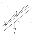
- the railroad section 1 is for example part of a subway or S-Bru line. Vehicles should be automatically controlled and run without a driver on the railway line. This requires, inter alia, obstacle detection.
- sensors are arranged, which observe the railway line.
- the sensors 2, 3 are designed as video cameras.
- the video cameras capture still images.
- the video cameras are connected via an optical line 4 to a central station 5.
- the optical line 4 is designed, for example, as an optical glass fiber line.
- the center 5 includes, for example, a processor and a memory.
- the images excluded from the video cameras are transmitted via the optical line 4 to the central station 5.
- Each video camera is assigned an address, which is transmitted with each transmission, in order to sort the images received in the center 5 can.
- Each video camera can subject the captured images to data compression before transmission.
- the images are converted electrically / optically before transmission.
- the images of all video cameras are transmitted, for example, in time-division multiplex to the central station 5.
- the images of all video cameras are evaluated centrally. For this purpose, the central station 5 compares the current images with reference images. If there is no difference between the current fixed image and the reference image in a comparison, the corresponding section of the route is free of obstacles.
- a classification of the obstacle can also be carried out.
- typical obstacles are stored as images in a memory.
- Typical obstacles include, for example, a train, a person, a fallen tree trunk, an animal.
- a comparison of a detected obstacle with a stored obstacle image can lead to early, automatic classification of the detected obstacle, which can result in various measures of elimination.
- the solid images can be made of a masking use. By comparison with the route of travel of a particular train present in the center 5, non-relevant obstacles, such as obstacles, can be detected. Countermatches are hidden. It is done in this way a masking of the track.
- one sensor or more than one sensor can be used for a track part of a railway track with at least two parallel tracks, one track being usually intended for the execution and another for the return direction.
- each currently transmitted solid image is divided into a plurality of solid images, wherein the number of solid images corresponds to the number of tracks. In each split solid image, a route is masked and an evaluation is made for this route. Using more than one sensor increases redundancy and security.
- Each sensor is essentially directed to a track and provided for monitoring a track. Due to the proximity of the tracks, a masking of individual routes will be necessary during the evaluation.
- the volume of data to be transferred is determined by the number of sensors. The more sensors used, the more data volume must be transferred.
- the viewing angles of the sensors overlap. In particular, in the event of a failure of a sensor, the fixed image recorded by a neighboring sensor can be used to evaluate the track to be monitored for the failed sensor. This increases security.
- the monitoring of individual parts of the track can already be done before a certain part of the track is released for a train to drive. If there are doubts as to whether an obstacle disturbs the flow of traffic, an alarm is triggered and a person can check the situation and decide on release or blocking on the basis of a monitor image.
- the sensors 2, 3 are designed such that they can be controlled telemetrically from the central station 5.
- the control takes place via the optical line 4.
- the control includes, for example, the pivoting of the sensors 2, 3.
- an attached to the sensor motor is provided in each case.
- each sensor 2, 3 includes a zoom. By telemetrically actuating the zoom, partial areas of the self-field can be enlarged. In the event of a malfunction, an operator is able to locate, call, establish a real-time connection and telemetrically control the sensor 2, 3 triggered by the central unit 5.
- the selection of a sensor 2, 3 via the optical line 4 by transmitting the address of the sensor 2, 3. After receiving a corresponding predetermined signal, the sensor 2, 3 switches to continuous operation.
- the center 5 has a control panel with several monitors and an overview of the railway line guidance and the sensors 2, 3.
- the center 5 By the real-time transmission of consecutive fixed images are transmitted to the center 5.
- video cameras the operator then sees a real-time video film from the disturbed track portion on a monitor. If necessary, sound is also transmitted.
- telemetry panning the camera and zooming the operator can focus the obstacle to better recognize it and then take appropriate action.
- the route clearance device has the task of releasing or blocking individual route parts for trains depending on the routes and currently traveled route sections. This is done e.g. et al using axle counters.
- a section of the track is now also blocked if a camera monitoring this section of the route detects an obstacle.
- a corresponding signal e.g. transmit a pre-known, stored alarm signal or control signal to the track device. This receives the signal and then blocks the stretch of road. If the route facility is responsible for locking and unlocking several parts of the route, the center 5 additionally transmits information about the route part to be blocked. After removing the obstacle of the corresponding track section is released again.
- sensors can be placed closer to each other for better monitoring compared to straight-lined, accessible areas.
- the automatic obstacle detection can be combined with arranged on the railway track sensors 2, 3 with the arranged on trains obstacle detection.
- video cameras are used as sensors, which operate in the optical range.
- sensors which work in the infrared range or in the area of radio waves (radar). By using these areas, the observation is largely independent of the weather.
- the evaluation of the recorded solid images is done centrally in the center.
- the sensors are very inexpensive to produce. Due to the high number of sensors, the implementation of the entire system is therefore cost-effective.
- the evaluation can be done completely or partially in the sensors. If a processor and a memory are provided in each sensor, then each sensor can compare current still images with a stored reference image and perform the obstacle detection autonomously for a route part. The result of the comparison is transmitted, for example, to the central office, which then initiates the further steps.
- the transmission volume can be reduced if in the normal case, i.
- a status message e.g. OK
- the corresponding fixed image or an alarm message can also be transmitted directly to a train which approaches the section of the route.
- the transmission is e.g. over radio or balises. The train receives in this way current and almost instantaneous alarm messages and can then initiate the braking process.
- an optical line between sensors and control center is used.
- an electrical line instead of an optical line, an electrical line, radio or a power line can be used.
- the electrical line eliminates the electro / optical conversion, so that the sensors can be made even cheaper.
- electrical lines are already available on the railway lines in most cases, so that a new installation is eliminated.
- the electrical lines are used, for example, for the transmission of Achszöhlersignale.
- the transmission takes place in a fixed transmission protocol.
- the protocol can also be used for transmitting the sensor signals. This eliminates the development of a new protocol.
- GSM Global System for Mobile Communication.
- time division multiplexing is used for the transmission of the sensor signals to the control center.
- Frequency Division Multiplexing or Code Division Multiplexing can also be used instead of time division multiplexing.
Landscapes
- Engineering & Computer Science (AREA)
- Mechanical Engineering (AREA)
- Train Traffic Observation, Control, And Security (AREA)
Claims (10)
- Procédé de détection d'obstacles de tout type sur des voies de chemin de fer (1) mises à disposition pour un moyen de transport à pilotage automatique et sans conducteur,
caractérisé en ce que
des capteurs (2, 3) sont disposés le long des voies de chemin de fer (1), capteurs au moyen desquels les voies de chemin de fer (1) sont observées,
les voies de chemin de fer (1) étant divisées en parties de voie connues, qui sont observées et surveillées respectivement par un capteur .(2, 3),
et l'ensemble des voies de chemin de fer (1) mises à disposition étant surveillé simultanément par les capteurs (2, 3) disposés le long des voies de chemin de fer (1), de sorte qu'une analyse automatique s'effectue, en ce qu'il s'effectue une retransmission automatique d'au moins une partie des résultats de l'analyse vers au moins un dispositif de libération de voie,
et en ce que chaque dispositif de libération de voie libère ou bloque les parties de voie définies pour la circulation en fonction des résultats reçus,
une partie de voie étant bloquée lorsqu'un capteur (2; 3) surveillant cette partie de voie détecte un obstacle, et une partie de voie étant automatiquement libérée lorsque aucun obstacle n'est détecté. - Procédé selon la revendication 1, caractérisé en ce que les capteurs (2, 3) sont conçus comme des caméras vidéo qui enregistrent des images fixes, et en ce que l'analyse s'effectue par comparaison des images fixes aux images de référence.
- Procédé selon la revendication 1, caractérisé en ce qu'un masquage de la voie s'effectue lors de l'analyse.
- Procédé selon la revendication 1, caractérisé en ce que les capteurs (2, 3) fonctionnent dans la plage optique, dans la gamme infrarouge ou dans la plage des ondes radio.
- Procédé selon la revendication 1, caractérisé en ce que l'analyse s'effectue de manière centrale.
- Procédé selon la revendication 1, caractérisé en ce que les capteurs (2, 3) sont commandés- de manière télémétrique.
- Système de réalisation du procédé selon la revendication 1, caractérisé en ce que les capteurs (2, 3) sont reliés par des conduites optiques (4) ou électriques, par radio ou par des câbles d'alimentation à une centrale (5), et en ce que la centrale (5) est adaptée pour communiquer par radio ou par l'intermédiaire de balises avec les trains à pilotage automatique roulant sur les voies de chemin de fer (1), et libérer ou bloquer certaines parties de voie pour la circulation des trains définies en fonction des résultats de l'analyse.
- Système selon la revendication 7, caractérisé en ce que la centrale (5) est adaptée pour réaliser de manière centrale l'analyse pour tous les capteurs (2, 3).
- Système selon la revendication 7, caractérisé en ce que l'analyse s'effectue partiellement ou entièrement dans les capteurs (2, 3).
- Système selon la revendication 7, caractérisé en ce que les capteurs (2, 3) sont conçus comme des caméras vidéo qui reçoivent des images fixes, de sorte que la transmission des images fixes enregistrées à la centrale (5) s'effectue au cours d'un procédé de multiplexage, une adresse étant allouée à chaque capteur (2, 3) et, au cours de chaque transmission d'une image fixe, l'adresse du capteur (2, 3) associé étant transmise conjointement.
Applications Claiming Priority (2)
| Application Number | Priority Date | Filing Date | Title |
|---|---|---|---|
| DE19958634A DE19958634A1 (de) | 1999-12-04 | 1999-12-04 | Verfahren zum Erkennen von Hindernissen auf Bahnstrecken |
| DE19958634 | 1999-12-04 |
Publications (4)
| Publication Number | Publication Date |
|---|---|
| EP1106470A1 EP1106470A1 (fr) | 2001-06-13 |
| EP1106470B1 EP1106470B1 (fr) | 2006-01-11 |
| EP1106470B2 true EP1106470B2 (fr) | 2008-10-15 |
| EP1106470B9 EP1106470B9 (fr) | 2009-03-25 |
Family
ID=7931515
Family Applications (1)
| Application Number | Title | Priority Date | Filing Date |
|---|---|---|---|
| EP00440305A Expired - Lifetime EP1106470B9 (fr) | 1999-12-04 | 2000-11-22 | Procédé pour détecter des obstacles sur des sections de voie de chemin de fer |
Country Status (5)
| Country | Link |
|---|---|
| US (1) | US6565046B2 (fr) |
| EP (1) | EP1106470B9 (fr) |
| AT (1) | ATE315513T1 (fr) |
| CA (1) | CA2327090A1 (fr) |
| DE (2) | DE19958634A1 (fr) |
Cited By (1)
| Publication number | Priority date | Publication date | Assignee | Title |
|---|---|---|---|---|
| CN109147388A (zh) * | 2018-08-16 | 2019-01-04 | 大连民族大学 | 判断道路行人为吸力关系的方法及系统 |
Families Citing this family (40)
| Publication number | Priority date | Publication date | Assignee | Title |
|---|---|---|---|---|
| US6961445B1 (en) * | 2001-05-04 | 2005-11-01 | Rockwell Collins | Image processing warning system |
| US6831573B2 (en) | 2002-10-15 | 2004-12-14 | Thomas L. Jones | Safety vehicle and system for avoiding train collisions and derailments |
| JP4342923B2 (ja) * | 2003-12-09 | 2009-10-14 | 大日本スクリーン製造株式会社 | 基板処理装置および基板処理方法 |
| DE102004024756A1 (de) * | 2004-05-12 | 2005-12-08 | Fraunhofer-Gesellschaft zur Förderung der angewandten Forschung e.V. | Videobasiertes Überwachungssystem und Verfahren an Gleis- oder Weichenabschnitten für die Zugschlussmeldung von Schienenfahrzeugen |
| CN1710841B (zh) * | 2004-06-16 | 2010-07-21 | 郑州捷安网络科技开发有限公司 | 列车车载无线自组网络通讯及列车状态实时监控系统 |
| DE102004032338A1 (de) * | 2004-07-02 | 2006-03-09 | Idas Informations-, Daten- Und Automationssysteme Gmbh | Verfahren und Überwachungsanlage zum Überwachen einer Gleisanlage |
| DE102005001404C5 (de) * | 2005-01-12 | 2016-06-09 | Kes Keschwari Electronic Systems Gmbh & Co. Kg | Verfahren und Einrichtung zum Aufbringen von Sand zwischen Rad und Schiene eines Schienenfahrzeugs |
| DE102005007336A1 (de) * | 2005-02-17 | 2006-08-31 | Siemens Ag | Bremsvorrichtung für ein Schienenfahrzeug |
| RU2294298C1 (ru) * | 2005-06-10 | 2007-02-27 | Евгений Николаевич Конев | Способ слежения за оперативной обстановкой на железной дороге, автоматизированная система слежения за оперативной обстановкой на железной дороге и система передачи и обработки информации для автоматизированной системы слежения на железной дороге |
| GB2427296B (en) * | 2005-06-13 | 2008-03-19 | Motorola Inc | Control station, mobile station, system and method for communication in object movement control |
| US20070170315A1 (en) * | 2006-01-20 | 2007-07-26 | Gedalyahu Manor | Method of detecting obstacles on railways and preventing train accidents |
| US8334906B2 (en) * | 2006-05-24 | 2012-12-18 | Objectvideo, Inc. | Video imagery-based sensor |
| DE102007010867A1 (de) * | 2007-03-02 | 2008-09-11 | Deutsches Zentrum für Luft- und Raumfahrt e.V. | Verfahren zum Betreiben eines Fahrzeugs |
| DE102008023504A1 (de) * | 2008-05-09 | 2009-11-19 | Siemens Aktiengesellschaft | Streckenüberwachungssystem für ein Fahrzeug und Verfahren zu dessen Betrieb |
| DE102009008077A1 (de) * | 2009-02-10 | 2010-08-19 | Siemens Aktiengesellschaft | Anordnung und Verfahren zur Detektion von Wärmestrahlung emittierenden Objekten auf Gleiskörpern |
| DE102009040713A1 (de) * | 2009-09-10 | 2011-03-24 | Deutsches Zentrum für Luft- und Raumfahrt e.V. | Überwachungssystem |
| DE102010023559A1 (de) | 2010-06-09 | 2011-12-15 | Siemens Aktiengesellschaft | Verfahren und Einrichtung zum Überwachen einer Strecke |
| US8693725B2 (en) | 2011-04-19 | 2014-04-08 | International Business Machines Corporation | Reliability in detecting rail crossing events |
| WO2013121344A2 (fr) * | 2012-02-17 | 2013-08-22 | Balaji Venkatraman | Système d'évaluation de vulnérabilité aux catastrophes ferroviaires et de guidage de sauvetage en temps réel utilisant une analyse informatique vidéo multicouche |
| FR3004574B1 (fr) * | 2013-04-16 | 2016-09-02 | Prodose | Dispositif de surveillance des voies ferrees et procede de travail |
| US10286930B2 (en) | 2015-06-16 | 2019-05-14 | The Johns Hopkins University | Instrumented rail system |
| DE102015212019A1 (de) * | 2015-06-29 | 2016-07-14 | Siemens Aktiengesellschaft | Verfahren und Vorrichtung zum Erkennen von Hindernissen vor einem Schienenfahrzeug |
| CN105657381A (zh) * | 2016-03-22 | 2016-06-08 | 大连理工大学 | 基于图像识别技术的渡槽渗漏实时预警光纤监测系统 |
| FR3052732B1 (fr) * | 2016-06-15 | 2018-10-05 | Alstom Transport Technologies | Procede de gestion d'un systeme de securite ferroviaire et systeme de securite ferroviaire mettant en oeuvre un tel procede |
| EP3275764B1 (fr) * | 2016-07-28 | 2020-10-14 | Max Räz | Systeme d'acheminement |
| DE102016216320A1 (de) | 2016-08-30 | 2018-03-01 | Siemens Aktiengesellschaft | Überwachung von streckengebundenen Transportsystemen |
| CN106572333A (zh) * | 2016-10-26 | 2017-04-19 | 中国铁道科学研究院通信信号研究所 | 一种无人值守列车障碍物检测系统 |
| DE102016224545A1 (de) * | 2016-12-09 | 2018-06-14 | Robert Bosch Gmbh | Verfahren zum Betreiben einer Rangierlok |
| WO2018213955A1 (fr) * | 2017-05-21 | 2018-11-29 | 李仁涛 | Appareil et procédé d'évitement d'obstacle de voiture sans conducteur |
| US20190054937A1 (en) * | 2017-08-15 | 2019-02-21 | Bnsf Railway Company | Unmanned aerial vehicle system for inspecting railroad assets |
| CN110716243A (zh) * | 2019-10-12 | 2020-01-21 | 国家电网有限公司 | 输电通道树障红外报警装置 |
| CN113240742A (zh) * | 2021-05-18 | 2021-08-10 | 西南交通大学 | 一种基于视觉像素链接直线检测的火车倒车辅助检测方法 |
| CN113486783A (zh) * | 2021-07-02 | 2021-10-08 | 浙江省交通投资集团有限公司智慧交通研究分公司 | 轨道交通车辆的障碍物检测方法及系统 |
| CN113928379B (zh) * | 2021-11-25 | 2024-06-04 | 交控科技股份有限公司 | 轨道区域安全防护系统及方法 |
| DE102021132173A1 (de) | 2021-12-07 | 2023-06-07 | Deutsche Bahn Aktiengesellschaft | Aufnahmeverfahren und aufnahmevorrichtung zur erzeugung einer bildinformation während eines betriebs eines schienenfahrzeugs |
| EP4389560A1 (fr) * | 2022-12-22 | 2024-06-26 | Siemens Mobility GmbH | Procédé et dispositif poiur tester une détection d'obstacles pour une zone dangereuse |
| EP4389558A1 (fr) * | 2022-12-23 | 2024-06-26 | Siemens Mobility GmbH | Procédé et dispositif pour tester une détection d'obstacles dans une zone dangereuse |
| CN116853326B (zh) * | 2023-09-05 | 2023-11-28 | 山西云井数通智能科技有限公司 | 一种矿用轨道车辆无人驾驶控制系统 |
| CN117104222B (zh) * | 2023-10-25 | 2023-12-29 | 广州市德赛西威智慧交通技术有限公司 | 一种应用于车辆行驶区域的障碍物检测方法及装置 |
| EP4656492A1 (fr) * | 2024-05-31 | 2025-12-03 | Siemens Mobility GmbH | Procédé de surveillance d'une section de voie ferrée à coté d'un quai |
Family Cites Families (17)
| Publication number | Priority date | Publication date | Assignee | Title |
|---|---|---|---|---|
| JPH03148373A (ja) * | 1989-11-01 | 1991-06-25 | Hitachi Ltd | 移動体監視モニタテレビシステム |
| JP2828324B2 (ja) * | 1990-06-21 | 1998-11-25 | 富士通株式会社 | 遠隔監視システム |
| DE4207688C1 (fr) * | 1992-03-11 | 1993-06-03 | Grundig E.M.V. Elektro-Mechanische Versuchsanstalt Max Grundig Hollaend. Stiftung & Co Kg, 8510 Fuerth, De | |
| JP3238486B2 (ja) * | 1992-09-03 | 2001-12-17 | 東海旅客鉄道株式会社 | 踏切監視装置 |
| JPH07228250A (ja) * | 1994-02-21 | 1995-08-29 | Teito Kousokudo Kotsu Eidan | 軌道内監視装置及びプラットホーム監視装置 |
| JP3179981B2 (ja) * | 1994-11-07 | 2001-06-25 | 三菱電機株式会社 | 列車運行管理システム |
| JP3361399B2 (ja) * | 1994-12-26 | 2003-01-07 | 株式会社日立製作所 | 障害物検知方法及びその装置 |
| CA2143977C (fr) * | 1995-01-31 | 1997-03-18 | Mark Krebs | Systeme de transmission de courrier video |
| US6088468A (en) * | 1995-05-17 | 2000-07-11 | Hitachi Denshi Kabushiki Kaisha | Method and apparatus for sensing object located within visual field of imaging device |
| IL117279A (en) * | 1996-02-27 | 2000-01-31 | Israel Aircraft Ind Ltd | System for detecting obstacles on a railway track |
| US5825412A (en) * | 1996-05-20 | 1998-10-20 | Esco Electronics Corporation | Video detection apparatus for monitoring a railroad crossing |
| DE19621612C2 (de) * | 1996-05-31 | 2001-03-01 | C Vis Comp Vision Und Automati | Vorrichtung zur Überwachung eines Gleisabschnittes in einem Bahnhof |
| US5785283A (en) * | 1996-11-25 | 1998-07-28 | Union Switch & Signal Inc. | System and method for communicating operational status of a railway wayside to a locomotive cab |
| DE19652588A1 (de) * | 1996-12-17 | 1998-06-18 | Alsthom Cge Alcatel | Verfahren zum automatischen Betrieb eines spurgebundenen Fahrzeugs auf Strecken mit gefährlichen Abschnitten sowie Kontrollsystem hierfür |
| DE19746570A1 (de) * | 1997-10-22 | 1999-05-06 | Daimler Chrysler Ag | Verfahren und Vorrichtung zur großflächigen Verkehrslageüberwachung |
| DE19811286C2 (de) * | 1998-03-16 | 2003-06-26 | Plettac Ag | Kamerabewegungssteuerung |
| DE19819624A1 (de) * | 1998-05-04 | 1999-11-18 | Ebs Eisenbahnsicherungs Ag Bas | Optische Rottenwarnanlage |
-
1999
- 1999-12-04 DE DE19958634A patent/DE19958634A1/de not_active Withdrawn
-
2000
- 2000-11-22 AT AT00440305T patent/ATE315513T1/de not_active IP Right Cessation
- 2000-11-22 EP EP00440305A patent/EP1106470B9/fr not_active Expired - Lifetime
- 2000-11-22 DE DE50012046T patent/DE50012046D1/de not_active Expired - Lifetime
- 2000-11-30 CA CA002327090A patent/CA2327090A1/fr not_active Abandoned
- 2000-11-30 US US09/726,039 patent/US6565046B2/en not_active Expired - Fee Related
Cited By (1)
| Publication number | Priority date | Publication date | Assignee | Title |
|---|---|---|---|---|
| CN109147388A (zh) * | 2018-08-16 | 2019-01-04 | 大连民族大学 | 判断道路行人为吸力关系的方法及系统 |
Also Published As
| Publication number | Publication date |
|---|---|
| DE19958634A1 (de) | 2001-06-21 |
| CA2327090A1 (fr) | 2001-06-04 |
| EP1106470B1 (fr) | 2006-01-11 |
| EP1106470B9 (fr) | 2009-03-25 |
| US20010002688A1 (en) | 2001-06-07 |
| ATE315513T1 (de) | 2006-02-15 |
| DE50012046D1 (de) | 2006-04-06 |
| EP1106470A1 (fr) | 2001-06-13 |
| US6565046B2 (en) | 2003-05-20 |
Similar Documents
| Publication | Publication Date | Title |
|---|---|---|
| EP1106470B2 (fr) | Procédé pour détecter des obstacles sur des sections de voie de chemin de fer | |
| US10618536B2 (en) | Method and system for managing specific events related to the movements of a guided vehicle | |
| EP3275764B1 (fr) | Systeme d'acheminement | |
| EP2872374A2 (fr) | Surveillance d'un tronçon de chemin de fer | |
| DE4321348C1 (de) | Verfahren und Vorrichtung zur Früherkennung und Meldung von Fehler- und Gefahrenquellen in schienengebundenen und schienenlosen Fahrzeugen des öffentlichen Nahverkehrs | |
| DE102015225241A1 (de) | Verfahren und System zur automatischen Steuerung eines Folgefahrzeugs mit einem Vorderfahrzeug | |
| DE102009040221A1 (de) | System und Verfahren zur sicheren Fernsteuerung von Fahrzeugen | |
| EP2206318B1 (fr) | Procédé de commande de communication | |
| CN216467864U (zh) | 一种铁路监控系统 | |
| DE102016216320A1 (de) | Überwachung von streckengebundenen Transportsystemen | |
| CN113859331A (zh) | 一种铁路监控系统及其监控方法 | |
| DE69920829T2 (de) | Kollisionsschutzsystem für Bahnübergang | |
| DE102007032091B3 (de) | Verfahren zum Überwachen eines höhengleichen Bahnübergangs | |
| DE10341426A1 (de) | Verfahren zur Raumüberwachung und Raumüberwachungsanlage | |
| DE10142250A1 (de) | Verfahren und Anordnung zur Steuerung eines Systems von mehreren Verkehrssignalen | |
| EP1288883A1 (fr) | Procédé et disposif pour contrôler un système de plusieurs signaux routiers | |
| DE102009040713A1 (de) | Überwachungssystem | |
| DE112005002483T5 (de) | System zur automatischen Ansage von Zügen | |
| DE202014011127U1 (de) | Programmierbare Bahnübergangs-Sicherheitsanlage mit kommunikativer Anbindung an dezentrale intelligente Peripherien | |
| EP3459813A1 (fr) | Système d'alerte pour train | |
| DE102010004653A1 (de) | Steuerungsverfahren und -anordnung für ein Schienenfahrzeug | |
| EP0286627B1 (fr) | Dispositif pour alerter des équipes | |
| DE10158678B4 (de) | Mobile Lichtsignalanlage und Verfahren zu ihrer Steuerung | |
| DE102007041718B4 (de) | Anordnung und Verfahren zur Absicherung von Arbeitsstellen im Gleisbereich | |
| DE102006029845B4 (de) | Vorrichtung und Verfahren zur Absicherung von Streckenabschnitten eines segmentierten Fahrweges für einen schienengebundenen Fahrzeugverband |
Legal Events
| Date | Code | Title | Description |
|---|---|---|---|
| PUAI | Public reference made under article 153(3) epc to a published international application that has entered the european phase |
Free format text: ORIGINAL CODE: 0009012 |
|
| AK | Designated contracting states |
Kind code of ref document: A1 Designated state(s): AT BE CH CY DE DK ES FI FR GB GR IE IT LI LU MC NL PT SE TR |
|
| AX | Request for extension of the european patent |
Free format text: AL;LT;LV;MK;RO;SI |
|
| 17P | Request for examination filed |
Effective date: 20010912 |
|
| AKX | Designation fees paid |
Free format text: AT BE CH CY DE DK ES FI FR GB GR IE IT LI LU MC NL PT SE TR |
|
| 17Q | First examination report despatched |
Effective date: 20040614 |
|
| RIC1 | Information provided on ipc code assigned before grant |
Ipc: 7B 61L 23/04 A |
|
| GRAP | Despatch of communication of intention to grant a patent |
Free format text: ORIGINAL CODE: EPIDOSNIGR1 |
|
| GRAS | Grant fee paid |
Free format text: ORIGINAL CODE: EPIDOSNIGR3 |
|
| GRAA | (expected) grant |
Free format text: ORIGINAL CODE: 0009210 |
|
| AK | Designated contracting states |
Kind code of ref document: B1 Designated state(s): AT BE CH CY DE DK ES FI FR GB GR IE IT LI LU MC NL PT SE TR |
|
| PG25 | Lapsed in a contracting state [announced via postgrant information from national office to epo] |
Ref country code: IT Free format text: LAPSE BECAUSE OF FAILURE TO SUBMIT A TRANSLATION OF THE DESCRIPTION OR TO PAY THE FEE WITHIN THE PRE;WARNING: LAPSES OF ITALIAN PATENTS WITH EFFECTIVE DATE BEFORE 2007 MAY HAVE OCCURRED AT ANY TIME BEFORE 2007. THE CORRECT EFFECTIVE DATE MAY BE DIFFERENT FROM THE ONE RECORDED.SCRIBED TIME-LIMIT Effective date: 20060111 Ref country code: NL Free format text: LAPSE BECAUSE OF FAILURE TO SUBMIT A TRANSLATION OF THE DESCRIPTION OR TO PAY THE FEE WITHIN THE PRESCRIBED TIME-LIMIT Effective date: 20060111 Ref country code: IE Free format text: LAPSE BECAUSE OF FAILURE TO SUBMIT A TRANSLATION OF THE DESCRIPTION OR TO PAY THE FEE WITHIN THE PRESCRIBED TIME-LIMIT Effective date: 20060111 Ref country code: FI Free format text: LAPSE BECAUSE OF FAILURE TO SUBMIT A TRANSLATION OF THE DESCRIPTION OR TO PAY THE FEE WITHIN THE PRESCRIBED TIME-LIMIT Effective date: 20060111 |
|
| REG | Reference to a national code |
Ref country code: CH Ref legal event code: EP |
|
| REG | Reference to a national code |
Ref country code: IE Ref legal event code: FG4D Free format text: LANGUAGE OF EP DOCUMENT: GERMAN |
|
| GBT | Gb: translation of ep patent filed (gb section 77(6)(a)/1977) |
Effective date: 20060214 |
|
| REF | Corresponds to: |
Ref document number: 50012046 Country of ref document: DE Date of ref document: 20060406 Kind code of ref document: P |
|
| PG25 | Lapsed in a contracting state [announced via postgrant information from national office to epo] |
Ref country code: SE Free format text: LAPSE BECAUSE OF FAILURE TO SUBMIT A TRANSLATION OF THE DESCRIPTION OR TO PAY THE FEE WITHIN THE PRESCRIBED TIME-LIMIT Effective date: 20060411 Ref country code: DK Free format text: LAPSE BECAUSE OF FAILURE TO SUBMIT A TRANSLATION OF THE DESCRIPTION OR TO PAY THE FEE WITHIN THE PRESCRIBED TIME-LIMIT Effective date: 20060411 |
|
| PG25 | Lapsed in a contracting state [announced via postgrant information from national office to epo] |
Ref country code: ES Free format text: LAPSE BECAUSE OF FAILURE TO SUBMIT A TRANSLATION OF THE DESCRIPTION OR TO PAY THE FEE WITHIN THE PRESCRIBED TIME-LIMIT Effective date: 20060422 |
|
| PG25 | Lapsed in a contracting state [announced via postgrant information from national office to epo] |
Ref country code: PT Free format text: LAPSE BECAUSE OF FAILURE TO SUBMIT A TRANSLATION OF THE DESCRIPTION OR TO PAY THE FEE WITHIN THE PRESCRIBED TIME-LIMIT Effective date: 20060612 |
|
| NLV1 | Nl: lapsed or annulled due to failure to fulfill the requirements of art. 29p and 29m of the patents act | ||
| ET | Fr: translation filed | ||
| REG | Reference to a national code |
Ref country code: IE Ref legal event code: FD4D |
|
| PLBI | Opposition filed |
Free format text: ORIGINAL CODE: 0009260 |
|
| PLAX | Notice of opposition and request to file observation + time limit sent |
Free format text: ORIGINAL CODE: EPIDOSNOBS2 |
|
| 26 | Opposition filed |
Opponent name: DEUTSCHE BAHN AG PATENTABTEILUNG Effective date: 20061011 |
|
| PG25 | Lapsed in a contracting state [announced via postgrant information from national office to epo] |
Ref country code: CH Free format text: LAPSE BECAUSE OF NON-PAYMENT OF DUE FEES Effective date: 20061130 Ref country code: LI Free format text: LAPSE BECAUSE OF NON-PAYMENT OF DUE FEES Effective date: 20061130 Ref country code: BE Free format text: LAPSE BECAUSE OF NON-PAYMENT OF DUE FEES Effective date: 20061130 Ref country code: MC Free format text: LAPSE BECAUSE OF NON-PAYMENT OF DUE FEES Effective date: 20061130 |
|
| PLBB | Reply of patent proprietor to notice(s) of opposition received |
Free format text: ORIGINAL CODE: EPIDOSNOBS3 |
|
| RAP2 | Party data changed (patent owner data changed or rights of a patent transferred) |
Owner name: ALCATEL LUCENT |
|
| REG | Reference to a national code |
Ref country code: CH Ref legal event code: PL |
|
| BERE | Be: lapsed |
Owner name: ALCATEL Effective date: 20061130 |
|
| PG25 | Lapsed in a contracting state [announced via postgrant information from national office to epo] |
Ref country code: AT Free format text: LAPSE BECAUSE OF NON-PAYMENT OF DUE FEES Effective date: 20061122 |
|
| PG25 | Lapsed in a contracting state [announced via postgrant information from national office to epo] |
Ref country code: GR Free format text: LAPSE BECAUSE OF FAILURE TO SUBMIT A TRANSLATION OF THE DESCRIPTION OR TO PAY THE FEE WITHIN THE PRESCRIBED TIME-LIMIT Effective date: 20060412 |
|
| PG25 | Lapsed in a contracting state [announced via postgrant information from national office to epo] |
Ref country code: LU Free format text: LAPSE BECAUSE OF NON-PAYMENT OF DUE FEES Effective date: 20061122 Ref country code: TR Free format text: LAPSE BECAUSE OF FAILURE TO SUBMIT A TRANSLATION OF THE DESCRIPTION OR TO PAY THE FEE WITHIN THE PRESCRIBED TIME-LIMIT Effective date: 20060111 |
|
| PUAH | Patent maintained in amended form |
Free format text: ORIGINAL CODE: 0009272 |
|
| STAA | Information on the status of an ep patent application or granted ep patent |
Free format text: STATUS: PATENT MAINTAINED AS AMENDED |
|
| 27A | Patent maintained in amended form |
Effective date: 20081015 |
|
| AK | Designated contracting states |
Kind code of ref document: B2 Designated state(s): AT BE CH CY DE DK ES FI FR GB GR IE IT LI LU MC NL PT SE TR |
|
| PG25 | Lapsed in a contracting state [announced via postgrant information from national office to epo] |
Ref country code: CY Free format text: LAPSE BECAUSE OF FAILURE TO SUBMIT A TRANSLATION OF THE DESCRIPTION OR TO PAY THE FEE WITHIN THE PRESCRIBED TIME-LIMIT Effective date: 20060111 |
|
| REG | Reference to a national code |
Ref country code: ES Ref legal event code: FD2A Effective date: 20061123 |
|
| PGFP | Annual fee paid to national office [announced via postgrant information from national office to epo] |
Ref country code: GB Payment date: 20131120 Year of fee payment: 14 Ref country code: DE Payment date: 20131120 Year of fee payment: 14 Ref country code: FR Payment date: 20131108 Year of fee payment: 14 |
|
| PGFP | Annual fee paid to national office [announced via postgrant information from national office to epo] |
Ref country code: IT Payment date: 20131111 Year of fee payment: 14 |
|
| REG | Reference to a national code |
Ref country code: DE Ref legal event code: R119 Ref document number: 50012046 Country of ref document: DE |
|
| REG | Reference to a national code |
Ref country code: FR Ref legal event code: CA Effective date: 20150521 |
|
| REG | Reference to a national code |
Ref country code: FR Ref legal event code: CA Effective date: 20150521 |
|
| GBPC | Gb: european patent ceased through non-payment of renewal fee |
Effective date: 20141122 |
|
| REG | Reference to a national code |
Ref country code: FR Ref legal event code: ST Effective date: 20150731 |
|
| PG25 | Lapsed in a contracting state [announced via postgrant information from national office to epo] |
Ref country code: DE Free format text: LAPSE BECAUSE OF NON-PAYMENT OF DUE FEES Effective date: 20150602 Ref country code: GB Free format text: LAPSE BECAUSE OF NON-PAYMENT OF DUE FEES Effective date: 20141122 |
|
| PG25 | Lapsed in a contracting state [announced via postgrant information from national office to epo] |
Ref country code: FR Free format text: LAPSE BECAUSE OF NON-PAYMENT OF DUE FEES Effective date: 20141201 |
|
| PG25 | Lapsed in a contracting state [announced via postgrant information from national office to epo] |
Ref country code: IT Free format text: LAPSE BECAUSE OF NON-PAYMENT OF DUE FEES Effective date: 20141122 |