EP1106549B1 - Méthode et dispositif pour alimenter des feuilles dans une ligne d'emballage - Google Patents
Méthode et dispositif pour alimenter des feuilles dans une ligne d'emballage Download PDFInfo
- Publication number
- EP1106549B1 EP1106549B1 EP00127002A EP00127002A EP1106549B1 EP 1106549 B1 EP1106549 B1 EP 1106549B1 EP 00127002 A EP00127002 A EP 00127002A EP 00127002 A EP00127002 A EP 00127002A EP 1106549 B1 EP1106549 B1 EP 1106549B1
- Authority
- EP
- European Patent Office
- Prior art keywords
- pickup roller
- sheet
- pickup
- roller
- axis
- Prior art date
- Legal status (The legal status is an assumption and is not a legal conclusion. Google has not performed a legal analysis and makes no representation as to the accuracy of the status listed.)
- Expired - Lifetime
Links
- 238000000034 method Methods 0.000 title claims description 15
- 230000033001 locomotion Effects 0.000 claims description 8
- 238000005096 rolling process Methods 0.000 claims description 8
- 230000002441 reversible effect Effects 0.000 claims description 4
- 230000005540 biological transmission Effects 0.000 claims description 2
- 235000019504 cigarettes Nutrition 0.000 description 5
- 238000012856 packing Methods 0.000 description 4
Images


Classifications
-
- B—PERFORMING OPERATIONS; TRANSPORTING
- B65—CONVEYING; PACKING; STORING; HANDLING THIN OR FILAMENTARY MATERIAL
- B65H—HANDLING THIN OR FILAMENTARY MATERIAL, e.g. SHEETS, WEBS, CABLES
- B65H3/00—Separating articles from piles
- B65H3/08—Separating articles from piles using pneumatic force
- B65H3/10—Suction rollers
Definitions
- the present invention relates to a method of feeding sheets to a wrapping line.
- the present invention may be used to advantage for feeding sheets to a wrapping line of a cigarette packing machine, to which the following description refers purely by way of example.
- Cigarette packing machines are known to employ a device for feeding sheets to a wrapping line as described in US Patent no. 4,918,908, whereby a suction pickup roller is rolled over and winds up a sheet located at the bottom opening of a hopper containing a stack of sheets. Once the sheet is wound fully, the pickup roller is arrested in a release position to release the sheet to an input conveyor of a wrapping line, which input conveyor is normally defined by two pickup rollers parallel and tangent to each other to engage the sheet in between.
- CH Patent no. 288,604 discloses a device for feeding sheets to a working line, whereby a suction pickup roller is rolled over and winds up a sheet located at the bottom opening of a hopper containing a stack of sheets; during the rolling of the suction pickup roller, the sheet partially wound up by the suction pickup roller is fed to a subsequent conveyor.
- US Patent no. 3,127,167 discloses a device for feeding sheets to a working line whereby a suction pickup roller is rolled over and winds up a sheet located at the upper opening of a hopper containing a stack of sheets. Once the sheet is wound around the suction pickup roller, such sheet is fed from the suction pickup roller to the working line.
- feed devices of the above type tend to severely stress and damage the sheets at relatively high operating speeds typical of modern packing machines, and particularly when releasing the sheets from the pickup roller to the input conveyor of the wrapping line.
- the present invention also relates to a device for feeding sheets to a wrapping line.
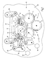
- Number 1 in Figure 1 indicates as a whole a device for feeding sheets 2 to a wrapping line 3 (shown only partly) of a known cigarette packing machine (not shown). More specifically, sheets 2 are labels, each of which is applied by wrapping line 3 to the outside of a respective packet of cigarettes (not shown).
- Feed device 1 comprises two vertical hoppers 4, each containing a respective stack 5 of sheets 2, and each having a respective bottom output opening 6 defining a pickup position 7 of sheets 2.
- Feed device 1 also comprises two suction pickup rollers 8, each having a respective axis 9 perpendicular to the Figure 1 plane, and each activated by a common actuating device 10 to withdraw a respective sheet 2 in pickup position 7, and to feed sheet 2 to a respective intermediate suction roller 11 having an axis 12 parallel to axes 9. From intermediate rollers 11, sheets 2 are transferred in known manner to a single suction input roller 13 of wrapping line 3 and then applied to respective packets of cigarettes (not shown).
- the above pickup rollers 8 may be replaced by different known rotary pickup members of other than substantially cylindrical shape.
- actuating device 10 imparts to each pickup roller 8 a rolling movement in contact with a respective sheet 2 in pickup position 7, so as to at least partly wind each sheet 2 about respective pickup roller 8.
- the rolling movement is imparted to each pickup roller 8 by actuating device 10 moving each pickup roller 8 in a traveling direction 14 perpendicular to respective axis 9, and at the same time rotating each pickup roller 8 about respective axis 9.
- Actuating device 10 then imparts to each pickup roller 8 a further rolling movement in contact with respective intermediate roller 11 to assist release of respective sheet 2 to respective intermediate roller 11; the rolling movement is imparted to each pickup roller 8 by combining a rotation of each pickup roller 8 about respective axis 9 with a rotation of respective intermediate roller 11 about respective axis 12. During release of each sheet 2 from respective pickup roller 8 to respective intermediate roller 11, each pickup roller 8 is rotated at the same surface speed but in the opposite direction with respect to respective intermediate roller 11.
- each intermediate roller 11 is replaced by a different type of intermediate conveyor.
- each pickup roller 8 continues rotating about respective axis 9 to assist release of respective sheet 2 to the corresponding intermediate conveyor.
- actuating device 10 moves said pickup roller 8 in direction 14 according to a given law of motion comprising an initial forward stage (shown in Figures 4a and 4b) to pick up sheet 2 and bring pickup roller 8 into a release position tangent to respective intermediate roller 11; a hold stage (shown in Figures 4c and 4d) to release sheet 2 to intermediate roller 11, and wherein the central axis 9 of rotation of pickup roller 8 is maintained in a fixed position; and a final return stage (shown in Figure 4e).
- a given law of motion comprising an initial forward stage (shown in Figures 4a and 4b) to pick up sheet 2 and bring pickup roller 8 into a release position tangent to respective intermediate roller 11; a hold stage (shown in Figures 4c and 4d) to release sheet 2 to intermediate roller 11, and wherein the central axis 9 of rotation of pickup roller 8 is maintained in a fixed position; and a final return stage (shown in Figure 4e).
- each pickup roller 8 rotates continuously and substantially uninterruptedly anticlockwise about respective axis 9, whereas, in the course of the return stage, each pickup roller 8 rotates clockwise about respective axis 9.
- each sheet 2 is wound completely about respective pickup roller 8, which then rotates about respective axis 9 until sheet 2 is released completely to respective intermediate roller 11.
- each pickup roller 8 only rotates about respective axis 9 until an initial portion of respective sheet 2 has been transferred to corresponding intermediate roller 11.
- Pickup rollers 8, intermediate rollers 11 and input roller 13 are known suction rollers, each of which gradually activates suction through its lateral surface during pickup of respective sheet 2, and gradually deactivates suction through its lateral surface during release of respective sheet 2.
- each suction pickup roller 8 comprises a cylindrical inner body 15 having a suction chamber 16 connected to a suction pump (not shown), and a release chamber 17 connected to the outside environment; and a cylindrical outer shell 18, which is coaxial with cylindrical inner body 15, rotates with respect to cylindrical inner body 15, and has a respective lateral surface 19 having a number of through holes 20 and for receiving said sheet.
- holes 20 communicate cyclically with chambers 16 and 17 to gradually and respectively activate and deactivate suction through lateral surface 19.
- each sheet 2 is therefore subjected to very little stress, by virtue of respective roller 8 rotating about respective axis 9 and so enabling roller 8 to accompany respective sheet 2 onto respective intermediate roller 11.
- actuating device 10 comprises a frame 21 supporting each pickup roller 8 for rotation about respective central axis 9; an actuating device 22 for moving frame 21 back and forth linearly in traveling direction 14; and an actuating device 23 for oscillating each pickup roller 8 about respective central axis 9.
- Actuating device 22 comprises a deformable articulated polygon 24, in turn comprising frame 21 and which is deformable to move frame 21 in traveling direction 14; and a reversible motor 25 for applying a force to deformable articulated polygon 24 to move frame 21 in traveling direction 14.
- Articulated polygon 24 is carried by a structure 26 supporting feed device 1, and comprises an arm 27 hinged at one end to frame 21; a triangular element 28 hinged to frame 21; an arm 29 hinged at one end to arm 27 and at the opposite end to supporting structure 26; an arm 30 hinged at one end to triangular element 28 and at the opposite end to supporting structure 26; and an arm 31 parallel to frame 21 and hinged at opposite ends to intermediate points of arms 29 and 30.
- Motor 25 is connected to triangular element 28 via the interposition of an arm 32, which is hinged at one end to triangular element 28 and is fitted at the opposite end to a shaft of motor 25.
- Actuating device 23 comprises a gear 33 fitted in rotary manner to frame 21 to oscillate about a respective axis 34 parallel to axes 9; two gears 35, each connected to gear 33 and integral with a respective pickup roller 8; and a reversible motor 36 for oscillating gear 33 about axis 34 by means of a known lever transmission mechanism 37.
Landscapes
- Engineering & Computer Science (AREA)
- Mechanical Engineering (AREA)
- Sheets, Magazines, And Separation Thereof (AREA)
- Basic Packing Technique (AREA)
Claims (23)
- Procédé d'alimentation en feuilles d'une ligne d'emballage, le procédé comprenant une première étape de transfert dans laquelle des feuilles (2) sont fournies de manière successive dans une position de prise (7) ; pour chaque feuille (2) se trouvant dans la position de prise (7), une seconde étape de transfert dans laquelle un rouleau de prise à aspiration (8) tourne le long de la feuille (2) afin d'enrouler au moins en partie la feuille (2) autour du rouleau de prise (8) ; et une troisième étape de transfert dans laquelle la feuille (2) est libérée sur un convoyeur intermédiaire (11) ; au cours de ladite troisième étape de transfert le rouleau de prise (8) tournant autour de son axe central respectif (9) afin de faciliter la libération de la feuille (2) sur le convoyeur intermédiaire (11) ; et procédé caractérisé en ce que, au cours de ladite troisième étape de transfert, ledit axe central (9) de rotation dudit rouleau de prise (8) est maintenu dans une position fixe, et en ce que ledit rouleau de prise (8) tourne en contact avec ledit convoyeur intermédiaire (11) afin de libérer la feuille (2) enroulée autour du rouleau de prise sur le convoyeur intermédiaire (11).
- Procédé selon la revendication 1, dans lequel, au cours de ladite seconde étape de transfert, ledit rouleau de prise (8) tourne contre ladite feuille (2) dans la position de prise (7) par translation du rouleau de prise (8) dans une direction d'avancement (14) perpendiculaire audit axe central (9) de rotation du rouleau de prise (8).
- Procédé selon la revendication 1 ou la revendication 2, dans lequel, au cours de ladite seconde étape de transfert, ladite feuille (2) dans la position de prise (7) est complètement enroulée autour dudit rouleau de prise (8).
- Procédé selon l'une quelconque des revendications 1 à 3, dans lequel, au cours de ladite troisième étape de transfert, ledit rouleau de prise (8) tourne d'un angle donné autour de son axe central respectif (9) de rotation de sorte qu'au moins une partie initiale de ladite feuille (2) est en prise dans ledit convoyeur intermédiaire (11).
- Procédé selon l'une quelconque des revendications 1 à 4, dans lequel, au cours de ladite troisième étape de transfert, ledit rouleau de prise (8) tourne d'un angle donné autour de son axe central respectif (9) de rotation de sorte que l'ensemble de ladite feuille (2) est sensiblement en prise dans ledit convoyeur intermédiaire (11).
- Procédé selon l'une quelconque des revendications 1 à 5, dans lequel, au cours de ladite seconde étape de transfert, ladite feuille (2) est enroulée le long d'une première surface latérale d'aspiration (19) dudit rouleau de prise (8) ; l'aspiration au travers de ladite première surface latérale d'aspiration (19) étant actionnée progressivement au cours de ladite seconde étape de transfert, et éliminée progressivement au cours de ladite troisième étape de transfert.
- Procédé selon l'une quelconque des revendications 1 à 6, dans lequel ledit convoyeur intermédiaire (11) est défini par un rouleau convoyeur à aspiration (11) ayant une seconde surface latérale d'aspiration destinée à recevoir ladite feuille (2) ; ledit rouleau de prise (8) étant tangent audit rouleau convoyeur (11) au cours de ladite troisième étape de transfert ; et l'aspiration au travers de ladite seconde surface latérale d'aspiration étant actionnée progressivement au cours de ladite troisième étape de transfert.
- Procédé selon la revendication 7, dans lequel, au cours de ladite troisième étape de transfert, ledit rouleau de prise (8) tourne à la même vitesse de surface mais dans la direction opposée par rapport audit rouleau convoyeur (11).
- Procédé selon l'une quelconque des revendications 1 à 8, dans lequel, au cours desdites étapes de transfert, ledit rouleau de prise (8) tourne dans la même direction à tout moment autour de son axe central respectif (9) de rotation.
- Dispositif d'alimentation d'une feuille sur une ligne d'emballage ; dispositif comprenant des moyens de transfert (4) destinés à fournir de manière successive des feuilles (2) dans une position de prise (7) ; au moins un rouleau de prise à aspiration (8) ayant un premier axe central (9) de rotation ; au moins un convoyeur intermédiaire (11) ; et des moyens de commande (10) destinés à imprimer audit rouleau de prise (8) un premier mouvement de rotation en contact avec ladite feuille (2) dans la position de prise (7), de manière à enrouler au moins en partie la feuille (2) autour du rouleau de prise (8) ; dispositif caractérisé en ce que lesdits moyens de commande (10) impriment audit rouleau de prise (8) un second mouvement de rotation en contact avec ledit convoyeur intermédiaire (11), afin de faciliter la libération de ladite feuille (2) sur ledit convoyeur intermédiaire (11).
- Dispositif selon la revendication 10, dans lequel lesdits moyens de transfert (4) comprennent une trémie (4) destinée à une pile (5) desdites feuilles (2) et comportant une ouverture inférieure (6) définissant ladite position de prise (7).
- Dispositif selon la revendication 10 ou la revendication 11, dans lequel lesdits moyens de commande (10) impriment audit rouleau de prise (8) une première et une seconde rotation autour dudit premier axe central (9) respectivement au cours dudit premier et dudit second mouvement de rotation, un déplacement dudit rouleau de prise (8) dans le sens transversal par rapport audit premier axe central (9) jusqu'à et à partir d'une position de libération, et le maintien du rouleau de prise (8) fixe dans ladite position de libération.
- Dispositif selon la revendication 12, dans lequel lesdites première et seconde rotations s'effectuent dans la même direction.
- Dispositif selon la revendication 12 ou la revendication 13, dans lequel ledit convoyeur intermédiaire (11) est défini par un rouleau convoyeur à aspiration (11) ayant un second axe (12) parallèle audit premier axe (9) ; au cours de la libération de ladite feuille (2) sur ledit convoyeur intermédiaire (11), ledit rouleau de prise (8) étant adjacent audit rouleau convoyeur (11).
- Dispositif selon l'une quelconque des revendications 10 à 14, dans lequel ledit rouleau de prise à aspiration (8) comprend un corps interne cylindrique (15) comportant au moins une chambre d'aspiration (16) ; et une coque externe cylindrique (18), qui est coaxiale audit corps interne cylindrique (15), tourne par rapport au corps interne cylindrique (15), et a une surface latérale respective (19) comportant un certain nombre de trous traversants (20), et destinée à recevoir ladite feuille (2).
- Dispositif selon l'une quelconque des revendications 10 à 15, dans lequel lesdits moyens de commande (10) comprennent un châssis (21) qui supporte ledit rouleau de prise (8) afin qu'il puisse tourner autour d'un premier axe central respectif (9) ; un premier dispositif de commande (22) destiné à déplacer de manière linéaire ledit châssis (21) vers l'avant et vers l'arrière dans une direction de déplacement (14) perpendiculaire audit premier axe (9) ; et un second dispositif de commande (23) destiné à faire osciller ledit rouleau de prise (8) autour dudit premier axe central (9).
- Dispositif selon la revendication 16, dans lequel ledit premier dispositif de commande (22) comprend un polygone articulé déformable (24), qui à son tour comprend ledit châssis (21) et qui peut être déformé afin de déplacer ledit châssis (21) dans ladite direction de déplacement (14) ; et un premier moteur réversible (25) destiné à appliquer une force sur ledit polygone articulé déformable (24).
- Dispositif selon la revendication 17, et comprenant un corps fixe (26) qui supporte ledit polygone articulé (24) ; le polygone articulé (24) comprenant un premier bras (27) en articulation sur une extrémité dudit châssis (21), un élément triangulaire (28) en articulation sur ledit châssis (21), un second bras (29) en articulation sur une extrémité dudit premier bras (27) et à une extrémité opposée dudit corps fixe (26), un troisième bras (30) en articulation sur une extrémité dudit élément triangulaire (28) et à une extrémité opposée dudit corps fixe (26), et un quatrième bras (31) qui est parallèle audit châssis (21) et en articulation aux extrémités opposées sur des points intermédiaires dudit second et dudit troisième bras (29, 30).
- Dispositif selon la revendication 18, dans lequel ledit premier moteur (25) est connecté audit élément triangulaire (28) ; ledit premier dispositif de commande (22) comprenant un cinquième bras (32) qui est en articulation sur une extrémité dudit élément triangulaire (28) et qui est ajusté sur une extrémité opposée d'un arbre dudit premier moteur (25).
- Dispositif selon l'une quelconque des revendications 16 à 19, dans lequel ledit second dispositif de commande (23) comprend un premier pignon monté en rotation sur ledit châssis (21) afin d'osciller autour d'un troisième axe (34) parallèle audit premier axe (9) ; un second pignon (35) connecté audit premier pignon (33) et formé intégralement avec ledit rouleau de prise (8) ; et un second moteur réversible (36) destiné à faire osciller ledit premier pignon (33) autour dudit troisième axe (34).
- Dispositif selon la revendication 20, dans lequel ledit second moteur (36) est connecté audit premier pignon (33) par un mécanisme de transmission à levier (37).
- Dispositif selon l'une quelconque des revendications 11 à 21, et comprenant deux desdites trémies (4), chacune contenant une pile respective (5) de feuilles (2) et ayant une ouverture de sortie respective (6) ; deux desdits rouleaux de prise à aspiration (8), chacun fonctionnant avec une desdites trémies respectives (4) ; et deux desdits convoyeurs intermédiaires (11), chacun fonctionnant avec un desdits rouleaux de prise (8) ; lesdits moyens de commande (10) étant connectés auxdits deux rouleaux de prise (8).
- Dispositif selon la revendication 16 ou 22, dans lequel ledit châssis (21) supporte lesdits deux rouleaux de prise (8) de manière à ce qu'ils tournent autour desdits premiers axes centraux respectifs (9).
Applications Claiming Priority (2)
| Application Number | Priority Date | Filing Date | Title |
|---|---|---|---|
| ITBO990669 | 1999-12-09 | ||
| IT1999BO000669A IT1311420B1 (it) | 1999-12-09 | 1999-12-09 | Metodo e dispositivo per l'alimentazione di fogli ad una linea diincarto. |
Publications (2)
| Publication Number | Publication Date |
|---|---|
| EP1106549A1 EP1106549A1 (fr) | 2001-06-13 |
| EP1106549B1 true EP1106549B1 (fr) | 2003-04-23 |
Family
ID=11344398
Family Applications (1)
| Application Number | Title | Priority Date | Filing Date |
|---|---|---|---|
| EP00127002A Expired - Lifetime EP1106549B1 (fr) | 1999-12-09 | 2000-12-08 | Méthode et dispositif pour alimenter des feuilles dans une ligne d'emballage |
Country Status (4)
| Country | Link |
|---|---|
| EP (1) | EP1106549B1 (fr) |
| DE (1) | DE60002284T2 (fr) |
| ES (1) | ES2195831T3 (fr) |
| IT (1) | IT1311420B1 (fr) |
Family Cites Families (7)
| Publication number | Priority date | Publication date | Assignee | Title |
|---|---|---|---|---|
| US3127167A (en) * | 1964-03-31 | Sheet stacker or feeder | ||
| CH288604A (de) * | 1949-10-15 | 1953-01-31 | Benz & Hilgers Gmbh | Vorrichtung zur Entnahme eines Blattes von einem Stapel. |
| DE2731632A1 (de) * | 1977-07-13 | 1979-02-01 | Hauni Werke Koerber & Co Kg | Vorrichtung zur einzelblattentnahme von der unterseite eines blattstapels, insbesondere eines zuschnittstapels fuer die tabakverarbeitende industrie |
| DD224836B1 (de) * | 1983-08-26 | 1988-09-28 | Polygraph Leipzig | Vorrichtung zum vereinzeln von bogen, insbes. von falzbogen |
| DE3738102C2 (de) * | 1987-11-10 | 2001-09-06 | Focke & Co | Vorrichtung zum Zuführen von Zuschnitten zu einem Verpackungsaggregat |
| DE4234377A1 (de) * | 1992-10-13 | 1994-04-14 | Focke & Co | Vorrichtung zum Speichern und Entnehmen von Zuschnitten |
| DE19805697A1 (de) * | 1998-02-06 | 1999-08-12 | Topack Verpacktech Gmbh | Vorrichtung zum Abziehen und Überführen flexibler streifenförmiger Gegenstände von der Unterseite eines Magazins zu einem anschließenden Transportmittel |
-
1999
- 1999-12-09 IT IT1999BO000669A patent/IT1311420B1/it active
-
2000
- 2000-12-08 ES ES00127002T patent/ES2195831T3/es not_active Expired - Lifetime
- 2000-12-08 EP EP00127002A patent/EP1106549B1/fr not_active Expired - Lifetime
- 2000-12-08 DE DE60002284T patent/DE60002284T2/de not_active Expired - Lifetime
Also Published As
| Publication number | Publication date |
|---|---|
| EP1106549A1 (fr) | 2001-06-13 |
| IT1311420B1 (it) | 2002-03-12 |
| ITBO990669A1 (it) | 2001-06-09 |
| ITBO990669A0 (it) | 1999-12-09 |
| DE60002284T2 (de) | 2003-12-04 |
| ES2195831T3 (es) | 2003-12-16 |
| DE60002284D1 (de) | 2003-05-28 |
Similar Documents
| Publication | Publication Date | Title |
|---|---|---|
| EP0608823B1 (fr) | Machine d'enveloppement, en particulier pour aliments tel des confiseries et analogues | |
| JPH03200518A (ja) | フラツトな物品を移送する装置 | |
| GB2198711A (en) | Carton delivery apparatus | |
| EP0940339B1 (fr) | Procédé continu pour envelopper des produits et machine | |
| EP0962390B1 (fr) | Unité et procédé pour former un groupe d'objets dans une machine d'emballage | |
| EP0940340B1 (fr) | Procédé et unité de transfert en continu d'un groupe de cigarettes entre des convoyeurs | |
| US20110002754A1 (en) | Method and equipment for preparing and applying folded leaflets | |
| ITBO950058A1 (it) | Macchina impacchettatrice continua di sigarette | |
| EP1640274A2 (fr) | Procédé et dispositif pour appliquer une étiquette sur un objet | |
| EP0563944B1 (fr) | Appareil pour appliquer en continu des étiquettes sur des articles | |
| JP3615896B2 (ja) | 2段積み包装装置,カートンピックアップ装置及びカートン箱型化装置 | |
| EP1106549A1 (fr) | Méthode et dispositif pour alimenter des feuilles dans une ligne d'emballage | |
| US6620085B2 (en) | System for transferring cardboard blanks in individual succession | |
| EP0687629B1 (fr) | Machine pour emballer des produits fragiles cylindriques, en particulier des cigarettes | |
| GB2127766A (en) | An apparatus for wrapping sweets | |
| RU2228887C2 (ru) | Упаковочная машина для сигарет | |
| GB2067150A (en) | A device for wrapping sweets | |
| EP1196339B1 (fr) | Appareil de transfert rotatif dote d'une came en ligne | |
| EP0803455B1 (fr) | Dispositif pour le transfert de produits | |
| ITBO980076A1 (it) | Metodo per il trasferimento di articoli. | |
| EP1275583B1 (fr) | Procédé et unité pour emballer des bonbons | |
| EP1780127B1 (fr) | Roue empaqueteuse | |
| EP0926071B1 (fr) | Unité pour lisser des bonbons enveloppés | |
| EP0706942B1 (fr) | Machine pour la fabrication de cigarettes en continu | |
| ITBO990057A1 (it) | Metodo e dispositivo per convogliamento di articoli . |
Legal Events
| Date | Code | Title | Description |
|---|---|---|---|
| PUAI | Public reference made under article 153(3) epc to a published international application that has entered the european phase |
Free format text: ORIGINAL CODE: 0009012 |
|
| AK | Designated contracting states |
Kind code of ref document: A1 Designated state(s): DE ES FR GB IT TR |
|
| AX | Request for extension of the european patent |
Free format text: AL;LT;LV;MK;RO;SI |
|
| 17P | Request for examination filed |
Effective date: 20011210 |
|
| AKX | Designation fees paid |
Free format text: DE ES FR GB IT TR |
|
| GRAH | Despatch of communication of intention to grant a patent |
Free format text: ORIGINAL CODE: EPIDOS IGRA |
|
| GRAH | Despatch of communication of intention to grant a patent |
Free format text: ORIGINAL CODE: EPIDOS IGRA |
|
| RAP1 | Party data changed (applicant data changed or rights of an application transferred) |
Owner name: G.D SOCIETA' PER AZIONI |
|
| GRAA | (expected) grant |
Free format text: ORIGINAL CODE: 0009210 |
|
| AK | Designated contracting states |
Designated state(s): DE ES FR GB IT TR |
|
| REG | Reference to a national code |
Ref country code: GB Ref legal event code: FG4D |
|
| REF | Corresponds to: |
Ref document number: 60002284 Country of ref document: DE Date of ref document: 20030528 Kind code of ref document: P |
|
| REG | Reference to a national code |
Ref country code: ES Ref legal event code: FG2A Ref document number: 2195831 Country of ref document: ES Kind code of ref document: T3 |
|
| ET | Fr: translation filed | ||
| PLBE | No opposition filed within time limit |
Free format text: ORIGINAL CODE: 0009261 |
|
| STAA | Information on the status of an ep patent application or granted ep patent |
Free format text: STATUS: NO OPPOSITION FILED WITHIN TIME LIMIT |
|
| 26N | No opposition filed |
Effective date: 20040126 |
|
| PGFP | Annual fee paid to national office [announced via postgrant information from national office to epo] |
Ref country code: TR Payment date: 20061128 Year of fee payment: 7 |
|
| PGFP | Annual fee paid to national office [announced via postgrant information from national office to epo] |
Ref country code: FR Payment date: 20061220 Year of fee payment: 7 |
|
| PGFP | Annual fee paid to national office [announced via postgrant information from national office to epo] |
Ref country code: ES Payment date: 20061226 Year of fee payment: 7 |
|
| PGFP | Annual fee paid to national office [announced via postgrant information from national office to epo] |
Ref country code: IT Payment date: 20061231 Year of fee payment: 7 |
|
| REG | Reference to a national code |
Ref country code: FR Ref legal event code: ST Effective date: 20081020 |
|
| REG | Reference to a national code |
Ref country code: ES Ref legal event code: FD2A Effective date: 20071210 |
|
| PG25 | Lapsed in a contracting state [announced via postgrant information from national office to epo] |
Ref country code: ES Free format text: LAPSE BECAUSE OF NON-PAYMENT OF DUE FEES Effective date: 20071210 Ref country code: FR Free format text: LAPSE BECAUSE OF NON-PAYMENT OF DUE FEES Effective date: 20071231 |
|
| PGFP | Annual fee paid to national office [announced via postgrant information from national office to epo] |
Ref country code: GB Payment date: 20081229 Year of fee payment: 9 |
|
| PG25 | Lapsed in a contracting state [announced via postgrant information from national office to epo] |
Ref country code: IT Free format text: LAPSE BECAUSE OF NON-PAYMENT OF DUE FEES Effective date: 20071208 |
|
| PG25 | Lapsed in a contracting state [announced via postgrant information from national office to epo] |
Ref country code: TR Free format text: LAPSE BECAUSE OF FAILURE TO SUBMIT A TRANSLATION OF THE DESCRIPTION OR TO PAY THE FEE WITHIN THE PRESCRIBED TIME-LIMIT Effective date: 20030423 |
|
| GBPC | Gb: european patent ceased through non-payment of renewal fee |
Effective date: 20091208 |
|
| PG25 | Lapsed in a contracting state [announced via postgrant information from national office to epo] |
Ref country code: GB Free format text: LAPSE BECAUSE OF NON-PAYMENT OF DUE FEES Effective date: 20091208 |
|
| PGFP | Annual fee paid to national office [announced via postgrant information from national office to epo] |
Ref country code: DE Payment date: 20131230 Year of fee payment: 14 |
|
| REG | Reference to a national code |
Ref country code: DE Ref legal event code: R119 Ref document number: 60002284 Country of ref document: DE |
|
| PG25 | Lapsed in a contracting state [announced via postgrant information from national office to epo] |
Ref country code: DE Free format text: LAPSE BECAUSE OF NON-PAYMENT OF DUE FEES Effective date: 20150701 |