EP1106773A1 - Befestigungsanordnung einer Antriebsvorrichtung und Bedienungseinheit eines Verschlusses oder einer Sonnenschutzanlage mit einer solchen Anordnung - Google Patents
Befestigungsanordnung einer Antriebsvorrichtung und Bedienungseinheit eines Verschlusses oder einer Sonnenschutzanlage mit einer solchen Anordnung Download PDFInfo
- Publication number
- EP1106773A1 EP1106773A1 EP00420241A EP00420241A EP1106773A1 EP 1106773 A1 EP1106773 A1 EP 1106773A1 EP 00420241 A EP00420241 A EP 00420241A EP 00420241 A EP00420241 A EP 00420241A EP 1106773 A1 EP1106773 A1 EP 1106773A1
- Authority
- EP
- European Patent Office
- Prior art keywords
- support
- head
- partition
- trunk
- cheek
- Prior art date
- Legal status (The legal status is an assumption and is not a legal conclusion. Google has not performed a legal analysis and makes no representation as to the accuracy of the status listed.)
- Granted
Links
Images


Classifications
-
- E—FIXED CONSTRUCTIONS
- E06—DOORS, WINDOWS, SHUTTERS, OR ROLLER BLINDS IN GENERAL; LADDERS
- E06B—FIXED OR MOVABLE CLOSURES FOR OPENINGS IN BUILDINGS, VEHICLES, FENCES OR LIKE ENCLOSURES IN GENERAL, e.g. DOORS, WINDOWS, BLINDS, GATES
- E06B9/00—Screening or protective devices for wall or similar openings, with or without operating or securing mechanisms; Closures of similar construction
- E06B9/02—Shutters, movable grilles, or other safety closing devices, e.g. against burglary
- E06B9/08—Roll-type closures
- E06B9/11—Roller shutters
- E06B9/17—Parts or details of roller shutters, e.g. suspension devices, shutter boxes, wicket doors, ventilation openings
- E06B9/174—Bearings specially adapted therefor
Definitions
- the invention relates to a device for fixing a drive member for a winding shaft, in a safe of a locking or protective installation solar.
- the invention also relates to a mechanism for operation of such an installation.
- a drive is generally placed in a trunk or box which can be of the type known from EP-A-0 764 759.
- This trunk includes a space delimited by a side wall of the trunk and by a cheek separating this space from the winding zone of the deck or blind on the aforementioned tree.
- a protruding part of the drive member which may be the head of an electric motor or part of a device mechanical intended to cooperate with a crank or a strap.
- the winding shaft and / or the drive member passes through a central opening in the cheek and support means for the drive member must be provided in this space, these means being most often complex and requiring the tightening of fixing screws.
- the cheek In addition to its function of delimitation of the aforementioned space, the cheek must ensure the guiding of the deck, with blades or flexible, so that it does not deflect parallel to the axis of the tree, to the point of blocking the installation operation.
- the cheek is not held in position in the trunk or box only from its edges and it tends to flex in its central zone under the effect of the forces transmitted by the apron. This has the effect of degrading winding the deck on the tree and reducing the duration life of the installation, especially since the section of the trunk is important.
- the lateral extension (s) of the support act as spacers between the cheek and the trunk end partition, these spacers can be arranged up to near the central opening of the cheek, so that it is effectively maintained in position across its width, including for a section chest important.
- the invention also relates to an operating mechanism a locking or sun protection system which includes a device as previously described.
- Such mechanism is easier to install and more reliable than state of the art mechanisms.
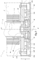
- the mechanism 1 shown in Figures 1 to 3 is provided for the operation of a roller shutter including the deck 2 shown in phantom is suitable for being wrapped around a shaft 3 controlled by an electric motor 4.
- the deck 2 can be with blades or formed from a flexible material.
- the motor 4 is housed inside the shaft 3 which is tubular, this shaft being supported in a trunk or box 5 shown in phantom and of which we note 5 c a lateral end partition.
- XX ′ the axis of rotation of the shaft 3 which is a longitudinal axis of the trunk 5.
- the internal volume of the box 5 includes a winding zone 6 of the deck 2 of the shaft 3 and a zone 7 of the head 4 has positioning the motor 4, the zone 7 being separated from the region 6 by a flange 8 breakthrough a central orifice 8 a for passage of the shaft 3 and of the motor 4.
- the head 4 a of the motor 4 is held in position inside the zone 7 by means of a support 10 mounted on the internal face 5 d of the partition 5 c .
- the support 10 comprises a central part 10 a forming a hollow housing 10 b capable of receiving at least part of the head 4 a .
- This housing 10 b is of generally octagonal section adapted to the end section 4 b of the head 4 a which is also octagonal.
- Two elastic tabs 10 c in the form of a hook are provided for locking the section 4b of the head 4 a in the housing 10 b by cooperation of shapes with suitable zones 4 c of the section 4 b .
- the geometry of the tabs 10 c and of the zones 4 c allows an elastic snap-fitting of the head 4 a in the housing 10 b .
- the bottom of the housing 10 b is pierced with an orifice 10 e intended to surround a central pin 5 e formed on the inner face 5 d of the partition 5 c and extending along the axis XX 'in the direction of the cheek 8
- the cooperation of the elements 5 e and 10 e allows an efficient and rapid positioning of the support 10 relative to the box 5.
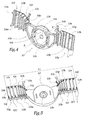
- the support 10 also includes two lateral extensions 10 f and 10 g extending, starting from the part 10 a , radially with respect to the axis XX '.
- the extensions 10 f and 10 g are in one piece with the central part 10 a of the support 10.
- the extensions 10 f and 10 g are formed by unitary elements 10 h linked together by breakable bands 10 i , these breakable bands being formed by a thinned part of each of the extensions 10 f and 10 g .
- each extension 10 f or 10 g is formed of eight elements 10 h connected by seven breakable strips 10 i .
- the number of 10 h elements of the 10 f and 10 g extensions results from a choice of design and can therefore vary.
- each element 10 h is provided with an inscription 10 j corresponding to a nominal diameter of box 5, that is to say substantially to the width l 5 of a box 5 to which the width l 10 of the support 10.
- a nominal diameter of box 5 that is to say substantially to the width l 5 of a box 5 to which the width l 10 of the support 10.
- Each element 10 h is also provided with a lug 10 k intended to be received in a hollow housing 5 k formed on the face 5 d of the partition 5.
- the respective diameters of each lug 10 k and each housing 5 k are adapted to obtain an immobilization of the support 10 relative to the partition 5 c by cooperation of shapes.
- Each element 10 h is also provided, on its rear face visible in FIG. 5, with a projecting part 10 l intended to come into abutment against the face 5 d of the partition 5 c when one of the pins 10 k is in place in one of the 5 k dwellings.
- the protruding parts 10 l form a discontinuous support zone on the partition 5 c which extends to the vicinity of the central part 10 a since the parts 10 l of all the elements 10 h not detached from the part 10 a are in abutment against the inner face 5 d of the partition 5 c .
- some of the elements 10 h carry projections 10 n and 10 m which bear against the face 8 b of the cheek 8 facing towards the zone 7.
- an element 10 h on two has 10 m and 10 n projections. It would be possible to provide that each element 10 h is provided with such projections or, on the contrary, that one element in three or more than three is provided with such projections.
- the projections 10 m and 10 n are distributed close to the central part 10 a of the support 10, so that they contribute to the positioning of the cheek 8 as far as the orifice 8 a , which avoids bending or bulging of the cheek 8 under the effect of the forces transmitted by the apron 2.
- the cheek 8 is thus kept substantially flat, so that it effectively guides the apron 2.
- the distance d between the ends of the projections 10 l on the one hand and 10 m or 10 n on the other hand, measured parallel to the axis XX ′ in the mounted configuration of the device, is equal to the desired width of the area 7, that is to say at the distance separating the faces 5 d and 8 b from the partition 5 c and from the cheek 8 parallel to this axis.
- the support 10 also includes two tabs 10 p and 10 g allowing the reception and immobilization by cooperation of shapes of an electronic circuit 11 for controlling the motor 4.
- the circuit 11 has been represented only by its card holder 11 and has a frame 11b, the card 11 has with practical components and connection paths between these components.
- the geometry of the frame 11b is such that it can be immobilized between tabs 10 r and backsplashes 10 s formed on the legs 10 p and 10 g .
- the installation and immobilization of the circuit 11 on the support 10 are carried out in a particularly simple manner and without interaction with the box 5, the dimensions of which can vary without influence on the installation of the circuit 11.
- the elements 10 p and 10 g , 10 r and 10 s therefore allow mounting by elastic snap-fitting of the circuit 11 on the support 10.
- the support 10 has been shown with the legs 10 p and 10 g integral with the second elements 10 h from the central part 10 a . According to a variant not shown of the invention, these tabs may be integral with the part 10 a , in which case they allow the mounting of the circuit 11 including in a small width trunk.
- the invention has been shown with an electric motor, however, it is applicable to an operating mechanism of a shutter or blind comprising a drive member mechanical part of which forming a "head" is provided for cooperate with a crank or strap.
Landscapes
- Engineering & Computer Science (AREA)
- Structural Engineering (AREA)
- Architecture (AREA)
- Civil Engineering (AREA)
- Operating, Guiding And Securing Of Roll- Type Closing Members (AREA)
- Photovoltaic Devices (AREA)
- Power-Operated Mechanisms For Wings (AREA)
- Control Of Motors That Do Not Use Commutators (AREA)
- Load-Engaging Elements For Cranes (AREA)
- Discharging, Photosensitive Material Shape In Electrophotography (AREA)
Applications Claiming Priority (2)
| Application Number | Priority Date | Filing Date | Title |
|---|---|---|---|
| FR9915109 | 1999-11-30 | ||
| FR9915109A FR2801632B1 (fr) | 1999-11-30 | 1999-11-30 | Dispositif de fixation d'un organe d'entrainement et mecanisme de manoeuvre d'une installation de fermeture ou de protection solaire comprenant un tel dispositif |
Publications (2)
| Publication Number | Publication Date |
|---|---|
| EP1106773A1 true EP1106773A1 (de) | 2001-06-13 |
| EP1106773B1 EP1106773B1 (de) | 2004-05-12 |
Family
ID=9552743
Family Applications (1)
| Application Number | Title | Priority Date | Filing Date |
|---|---|---|---|
| EP00420241A Expired - Lifetime EP1106773B1 (de) | 1999-11-30 | 2000-11-22 | Befestigungsanordnung einer Antriebsvorrichtung und Bedienungseinheit eines Verschlusses oder einer Sonnenschutzanlage mit einer solchen Anordnung |
Country Status (8)
| Country | Link |
|---|---|
| EP (1) | EP1106773B1 (de) |
| AT (1) | ATE266794T1 (de) |
| AU (1) | AU7176300A (de) |
| DE (1) | DE60010630T2 (de) |
| ES (1) | ES2220374T3 (de) |
| FR (1) | FR2801632B1 (de) |
| PL (1) | PL196827B1 (de) |
| PT (1) | PT1106773E (de) |
Cited By (4)
| Publication number | Priority date | Publication date | Assignee | Title |
|---|---|---|---|---|
| FR2898380A1 (fr) * | 2006-03-08 | 2007-09-14 | Zurfluh Feller Soc Par Actions | Console pour supporter un arbre de volet roulant, et montage de volet roulant avec une telle console. |
| FR2901304A1 (fr) * | 2006-05-22 | 2007-11-23 | Deprat Jean Sa Sa | Volet roulant ou similaire |
| FR3020395A1 (fr) * | 2014-04-25 | 2015-10-30 | Simu | Dispositif de fixation d'un mecanisme d'entrainement motorise d'un tube d'enroulement d'un ecran dans un coffre et installation domotique comprenant un tel dispositif |
| EP3216972A1 (de) * | 2016-03-10 | 2017-09-13 | Roma Kg | Gebäudeöffnungsverschattungsvorrichtung und lageranordnung dafür |
Families Citing this family (1)
| Publication number | Priority date | Publication date | Assignee | Title |
|---|---|---|---|---|
| CN106150328B (zh) * | 2015-03-31 | 2018-03-23 | 林雅莹 | 窗帘的卷收减速器 |
Citations (2)
| Publication number | Priority date | Publication date | Assignee | Title |
|---|---|---|---|---|
| EP0668430A1 (de) * | 1994-02-18 | 1995-08-23 | I.M.B.A.C. S.p.a. | Tragevorrichtung für Rolladenantrieb |
| EP0764759A2 (de) * | 1995-09-25 | 1997-03-26 | I.M.B.A.C. S.p.a. | Kopfschiene für Rollvorhänge |
-
1999
- 1999-11-30 FR FR9915109A patent/FR2801632B1/fr not_active Expired - Fee Related
-
2000
- 2000-11-22 ES ES00420241T patent/ES2220374T3/es not_active Expired - Lifetime
- 2000-11-22 DE DE60010630T patent/DE60010630T2/de not_active Expired - Fee Related
- 2000-11-22 AU AU71763/00A patent/AU7176300A/en not_active Abandoned
- 2000-11-22 PT PT00420241T patent/PT1106773E/pt unknown
- 2000-11-22 AT AT00420241T patent/ATE266794T1/de not_active IP Right Cessation
- 2000-11-22 EP EP00420241A patent/EP1106773B1/de not_active Expired - Lifetime
- 2000-11-28 PL PL344192A patent/PL196827B1/pl not_active IP Right Cessation
Patent Citations (2)
| Publication number | Priority date | Publication date | Assignee | Title |
|---|---|---|---|---|
| EP0668430A1 (de) * | 1994-02-18 | 1995-08-23 | I.M.B.A.C. S.p.a. | Tragevorrichtung für Rolladenantrieb |
| EP0764759A2 (de) * | 1995-09-25 | 1997-03-26 | I.M.B.A.C. S.p.a. | Kopfschiene für Rollvorhänge |
Cited By (5)
| Publication number | Priority date | Publication date | Assignee | Title |
|---|---|---|---|---|
| FR2898380A1 (fr) * | 2006-03-08 | 2007-09-14 | Zurfluh Feller Soc Par Actions | Console pour supporter un arbre de volet roulant, et montage de volet roulant avec une telle console. |
| EP1832708A3 (de) * | 2006-03-08 | 2007-12-05 | Zurfluh Feller | Träger zum Tragen einer Rollladenwelle und Montage des Rollladens mit einem solchen Träger |
| FR2901304A1 (fr) * | 2006-05-22 | 2007-11-23 | Deprat Jean Sa Sa | Volet roulant ou similaire |
| FR3020395A1 (fr) * | 2014-04-25 | 2015-10-30 | Simu | Dispositif de fixation d'un mecanisme d'entrainement motorise d'un tube d'enroulement d'un ecran dans un coffre et installation domotique comprenant un tel dispositif |
| EP3216972A1 (de) * | 2016-03-10 | 2017-09-13 | Roma Kg | Gebäudeöffnungsverschattungsvorrichtung und lageranordnung dafür |
Also Published As
| Publication number | Publication date |
|---|---|
| FR2801632A1 (fr) | 2001-06-01 |
| AU7176300A (en) | 2001-05-31 |
| ATE266794T1 (de) | 2004-05-15 |
| EP1106773B1 (de) | 2004-05-12 |
| PL196827B1 (pl) | 2008-02-29 |
| PL344192A1 (en) | 2001-06-04 |
| ES2220374T3 (es) | 2004-12-16 |
| DE60010630D1 (de) | 2004-06-17 |
| DE60010630T2 (de) | 2005-05-19 |
| PT1106773E (pt) | 2004-08-31 |
| FR2801632B1 (fr) | 2002-01-18 |
Similar Documents
| Publication | Publication Date | Title |
|---|---|---|
| EP0479719B1 (de) | Aufrolleinrichtung mit rohrförmigem Motor für Stores, Jalousien oder dergleichen | |
| EP1090788B1 (de) | Anordnung mit einer inneren Auskleidung einer Fahrzeugtür und einem Fensterhebermechanismus befestigt an dieser Auskleidung | |
| EP0023278B1 (de) | Vorschubvorrichtung für einen Träger in Lochbandform | |
| FR2697867A1 (fr) | Moto-réducteur électrique à réducteur épicycloïdal et à frein automatique pour fermetures souples du type équilibré. | |
| EP1106775A1 (de) | Befestigungsvorrichtung für eine Aufwickelwelle und Betätigungsmechanismus für eine Verschlusseinrichtung oder einen Sonnenschutz mit einer solchen Vorrichtung | |
| EP1106774B1 (de) | Vorrichtung zum Fixieren eines Antriebs, und Betätigungsmechanismus einer Schliess- oder Sonnenschutzeinrichtung mit solcher Vorrichtung | |
| EP1106773B1 (de) | Befestigungsanordnung einer Antriebsvorrichtung und Bedienungseinheit eines Verschlusses oder einer Sonnenschutzanlage mit einer solchen Anordnung | |
| FR2482863A1 (fr) | Appareil de rappel en enroulement d'une bande de ceinture individuelle de securite, par ressort, en non-utilisation dans un vehicule automobile | |
| FR3149636A1 (fr) | Actionneur électromécanique et dispositif d’occultation comprenant un tel actionneur | |
| FR2781550A1 (fr) | Procede de changement d'une cartouche filtrante montee dans un conduit d'ecoulement d'un fluide et agencement pour la mise en oeuvre du procede | |
| FR2746715A1 (fr) | Dispositif de commande d'un flux d'air, en particulier pour une installation de chauffage et/ou climatisation de vehicule automobile | |
| EP1059415B1 (de) | Gurtaufroller, Rolladen- oder Storebetätigungsmechanismus mit einem solchen Aufroller und Verfahren zur Herstellung eines solchen Aufrollers | |
| EP1607568B1 (de) | Halter einer Wickelwelle und entsprechender Vorhang oder Sonnenschutz | |
| EP1160414A1 (de) | Endhalterung für eine Wickelwelle, Verfahren zur Herstellung und Antriebsmechanismus einer Schliess- oder Sonnenschutzeinrichtung mit solcher Vorrichtung | |
| EP1571287B1 (de) | Rolladen zum Schutz einer Öffnung, insbesondere eines Fensters, einer Tür oder dergleichen | |
| FR2715690A1 (fr) | Agencement de support pivotant d'un ouvrant à une partie fixe formant dormant. | |
| FR2793836A1 (fr) | Store a enrouleur a bouchon de tube d'enroulement non coaxial | |
| EP1644607B1 (de) | Falttor und vorrichtung zur führung des torblattes | |
| FR2562945A3 (fr) | Piece d'appui destinee notamment a un rouleau pour volets ou stores roulants | |
| EP1231355A1 (de) | Vorrichtung zur Immobilisierung einer Antriebsvorrichtung und Bedienungseinheit eines Verschlusses oder einer Sonnenschutzanlage mit einer solchen Anordnung | |
| EP0096137A1 (de) | Aufwickelvorrichtung in Gehäuse | |
| FR2746716A1 (fr) | Dispositif de commande d'un flux d'air, notamment pour une installation de chauffage et/ou climatisation de vehicule automobile | |
| EP0945585B1 (de) | Rolladen mit Handantrieb | |
| FR2845725A1 (fr) | Coffre de store | |
| EP1241319A1 (de) | Sicherheitseinrichtung für eine Schliess- oder Sonnenschutzeinrichtung und Bedienungseinheit dieser Einrichtung |
Legal Events
| Date | Code | Title | Description |
|---|---|---|---|
| PUAI | Public reference made under article 153(3) epc to a published international application that has entered the european phase |
Free format text: ORIGINAL CODE: 0009012 |
|
| AK | Designated contracting states |
Kind code of ref document: A1 Designated state(s): AT BE CH CY DE DK ES FI FR GB GR IE IT LI LU MC NL PT SE TR |
|
| AX | Request for extension of the european patent |
Free format text: AL;LT;LV;MK;RO;SI |
|
| 17P | Request for examination filed |
Effective date: 20011206 |
|
| AKX | Designation fees paid |
Free format text: AT BE CH CY DE DK ES FI FR GB GR IE IT LI LU MC NL PT SE TR |
|
| RAP1 | Party data changed (applicant data changed or rights of an application transferred) |
Owner name: GAVIOTA SIMBAC, S.L. |
|
| 17Q | First examination report despatched |
Effective date: 20030901 |
|
| GRAP | Despatch of communication of intention to grant a patent |
Free format text: ORIGINAL CODE: EPIDOSNIGR1 |
|
| GRAS | Grant fee paid |
Free format text: ORIGINAL CODE: EPIDOSNIGR3 |
|
| GRAA | (expected) grant |
Free format text: ORIGINAL CODE: 0009210 |
|
| AK | Designated contracting states |
Kind code of ref document: B1 Designated state(s): AT BE CH CY DE DK ES FI FR GB GR IE IT LI LU MC NL PT SE TR |
|
| PG25 | Lapsed in a contracting state [announced via postgrant information from national office to epo] |
Ref country code: IE Free format text: LAPSE BECAUSE OF FAILURE TO SUBMIT A TRANSLATION OF THE DESCRIPTION OR TO PAY THE FEE WITHIN THE PRESCRIBED TIME-LIMIT Effective date: 20040512 Ref country code: FI Free format text: LAPSE BECAUSE OF FAILURE TO SUBMIT A TRANSLATION OF THE DESCRIPTION OR TO PAY THE FEE WITHIN THE PRESCRIBED TIME-LIMIT Effective date: 20040512 Ref country code: CY Free format text: LAPSE BECAUSE OF FAILURE TO SUBMIT A TRANSLATION OF THE DESCRIPTION OR TO PAY THE FEE WITHIN THE PRESCRIBED TIME-LIMIT Effective date: 20040512 Ref country code: GB Free format text: LAPSE BECAUSE OF FAILURE TO SUBMIT A TRANSLATION OF THE DESCRIPTION OR TO PAY THE FEE WITHIN THE PRESCRIBED TIME-LIMIT Effective date: 20040512 Ref country code: TR Free format text: LAPSE BECAUSE OF FAILURE TO SUBMIT A TRANSLATION OF THE DESCRIPTION OR TO PAY THE FEE WITHIN THE PRESCRIBED TIME-LIMIT Effective date: 20040512 Ref country code: AT Free format text: LAPSE BECAUSE OF FAILURE TO SUBMIT A TRANSLATION OF THE DESCRIPTION OR TO PAY THE FEE WITHIN THE PRESCRIBED TIME-LIMIT Effective date: 20040512 |
|
| REG | Reference to a national code |
Ref country code: GB Ref legal event code: FG4D Free format text: NOT ENGLISH |
|
| REG | Reference to a national code |
Ref country code: CH Ref legal event code: EP |
|
| REG | Reference to a national code |
Ref country code: IE Ref legal event code: FG4D Free format text: FRENCH |
|
| REF | Corresponds to: |
Ref document number: 60010630 Country of ref document: DE Date of ref document: 20040617 Kind code of ref document: P |
|
| PG25 | Lapsed in a contracting state [announced via postgrant information from national office to epo] |
Ref country code: GR Free format text: LAPSE BECAUSE OF FAILURE TO SUBMIT A TRANSLATION OF THE DESCRIPTION OR TO PAY THE FEE WITHIN THE PRESCRIBED TIME-LIMIT Effective date: 20040812 Ref country code: DK Free format text: LAPSE BECAUSE OF FAILURE TO SUBMIT A TRANSLATION OF THE DESCRIPTION OR TO PAY THE FEE WITHIN THE PRESCRIBED TIME-LIMIT Effective date: 20040812 Ref country code: SE Free format text: LAPSE BECAUSE OF FAILURE TO SUBMIT A TRANSLATION OF THE DESCRIPTION OR TO PAY THE FEE WITHIN THE PRESCRIBED TIME-LIMIT Effective date: 20040812 |
|
| REG | Reference to a national code |
Ref country code: PT Ref legal event code: SC4A Free format text: AVAILABILITY OF NATIONAL TRANSLATION Effective date: 20040618 |
|
| GBV | Gb: ep patent (uk) treated as always having been void in accordance with gb section 77(7)/1977 [no translation filed] |
Effective date: 20040512 |
|
| PG25 | Lapsed in a contracting state [announced via postgrant information from national office to epo] |
Ref country code: LU Free format text: LAPSE BECAUSE OF NON-PAYMENT OF DUE FEES Effective date: 20041122 |
|
| PG25 | Lapsed in a contracting state [announced via postgrant information from national office to epo] |
Ref country code: LI Free format text: LAPSE BECAUSE OF NON-PAYMENT OF DUE FEES Effective date: 20041130 Ref country code: MC Free format text: LAPSE BECAUSE OF NON-PAYMENT OF DUE FEES Effective date: 20041130 Ref country code: CH Free format text: LAPSE BECAUSE OF NON-PAYMENT OF DUE FEES Effective date: 20041130 |
|
| REG | Reference to a national code |
Ref country code: ES Ref legal event code: FG2A Ref document number: 2220374 Country of ref document: ES Kind code of ref document: T3 |
|
| REG | Reference to a national code |
Ref country code: IE Ref legal event code: FD4D |
|
| PLBE | No opposition filed within time limit |
Free format text: ORIGINAL CODE: 0009261 |
|
| STAA | Information on the status of an ep patent application or granted ep patent |
Free format text: STATUS: NO OPPOSITION FILED WITHIN TIME LIMIT |
|
| 26N | No opposition filed |
Effective date: 20050215 |
|
| REG | Reference to a national code |
Ref country code: CH Ref legal event code: PL |
|
| PGFP | Annual fee paid to national office [announced via postgrant information from national office to epo] |
Ref country code: PT Payment date: 20051219 Year of fee payment: 6 |
|
| PG25 | Lapsed in a contracting state [announced via postgrant information from national office to epo] |
Ref country code: PT Free format text: LAPSE BECAUSE OF NON-PAYMENT OF DUE FEES Effective date: 20070522 |
|
| REG | Reference to a national code |
Ref country code: PT Ref legal event code: MM4A Free format text: LAPSE DUE TO NON-PAYMENT OF FEES Effective date: 20070522 |
|
| PGFP | Annual fee paid to national office [announced via postgrant information from national office to epo] |
Ref country code: ES Payment date: 20071112 Year of fee payment: 8 Ref country code: NL Payment date: 20071130 Year of fee payment: 8 |
|
| PGFP | Annual fee paid to national office [announced via postgrant information from national office to epo] |
Ref country code: IT Payment date: 20071130 Year of fee payment: 8 |
|
| PGFP | Annual fee paid to national office [announced via postgrant information from national office to epo] |
Ref country code: BE Payment date: 20071005 Year of fee payment: 8 |
|
| PGFP | Annual fee paid to national office [announced via postgrant information from national office to epo] |
Ref country code: FR Payment date: 20070927 Year of fee payment: 8 |
|
| PGFP | Annual fee paid to national office [announced via postgrant information from national office to epo] |
Ref country code: DE Payment date: 20080129 Year of fee payment: 8 |
|
| BERE | Be: lapsed |
Owner name: *GAVIOTA SIMBAC S.L. Effective date: 20081130 |
|
| PG25 | Lapsed in a contracting state [announced via postgrant information from national office to epo] |
Ref country code: NL Free format text: LAPSE BECAUSE OF NON-PAYMENT OF DUE FEES Effective date: 20090601 |
|
| NLV4 | Nl: lapsed or anulled due to non-payment of the annual fee |
Effective date: 20090601 |
|
| PG25 | Lapsed in a contracting state [announced via postgrant information from national office to epo] |
Ref country code: IT Free format text: LAPSE BECAUSE OF NON-PAYMENT OF DUE FEES Effective date: 20081122 |
|
| REG | Reference to a national code |
Ref country code: FR Ref legal event code: ST Effective date: 20090731 |
|
| PG25 | Lapsed in a contracting state [announced via postgrant information from national office to epo] |
Ref country code: BE Free format text: LAPSE BECAUSE OF NON-PAYMENT OF DUE FEES Effective date: 20081130 |
|
| PG25 | Lapsed in a contracting state [announced via postgrant information from national office to epo] |
Ref country code: DE Free format text: LAPSE BECAUSE OF NON-PAYMENT OF DUE FEES Effective date: 20090603 |
|
| REG | Reference to a national code |
Ref country code: ES Ref legal event code: FD2A Effective date: 20081124 |
|
| PG25 | Lapsed in a contracting state [announced via postgrant information from national office to epo] |
Ref country code: ES Free format text: LAPSE BECAUSE OF NON-PAYMENT OF DUE FEES Effective date: 20081124 |
|
| PG25 | Lapsed in a contracting state [announced via postgrant information from national office to epo] |
Ref country code: FR Free format text: LAPSE BECAUSE OF NON-PAYMENT OF DUE FEES Effective date: 20081130 |