EP1106873B1 - Steuerung für automatische Fahrzeuggetriebe - Google Patents
Steuerung für automatische Fahrzeuggetriebe Download PDFInfo
- Publication number
- EP1106873B1 EP1106873B1 EP00126972A EP00126972A EP1106873B1 EP 1106873 B1 EP1106873 B1 EP 1106873B1 EP 00126972 A EP00126972 A EP 00126972A EP 00126972 A EP00126972 A EP 00126972A EP 1106873 B1 EP1106873 B1 EP 1106873B1
- Authority
- EP
- European Patent Office
- Prior art keywords
- torque
- engine
- calculating means
- vehicle
- calculating
- Prior art date
- Legal status (The legal status is an assumption and is not a legal conclusion. Google has not performed a legal analysis and makes no representation as to the accuracy of the status listed.)
- Expired - Lifetime
Links
- 230000005540 biological transmission Effects 0.000 title claims abstract description 41
- 230000003247 decreasing effect Effects 0.000 claims description 9
- 238000002485 combustion reaction Methods 0.000 claims description 4
- 230000035939 shock Effects 0.000 abstract description 14
- 238000006243 chemical reaction Methods 0.000 description 5
- 238000005259 measurement Methods 0.000 description 3
- 230000000994 depressogenic effect Effects 0.000 description 2
- 238000010586 diagram Methods 0.000 description 2
- 230000001133 acceleration Effects 0.000 description 1
- 239000012530 fluid Substances 0.000 description 1
- XDDAORKBJWWYJS-UHFFFAOYSA-N glyphosate Chemical compound OC(=O)CNCP(O)(O)=O XDDAORKBJWWYJS-UHFFFAOYSA-N 0.000 description 1
- 230000005484 gravity Effects 0.000 description 1
- 230000003068 static effect Effects 0.000 description 1
Images


Classifications
-
- F—MECHANICAL ENGINEERING; LIGHTING; HEATING; WEAPONS; BLASTING
- F16—ENGINEERING ELEMENTS AND UNITS; GENERAL MEASURES FOR PRODUCING AND MAINTAINING EFFECTIVE FUNCTIONING OF MACHINES OR INSTALLATIONS; THERMAL INSULATION IN GENERAL
- F16H—GEARING
- F16H61/00—Control functions within control units of change-speed- or reversing-gearings for conveying rotary motion ; Control of exclusively fluid gearing, friction gearing, gearings with endless flexible members or other particular types of gearing
- F16H61/04—Smoothing ratio shift
- F16H61/06—Smoothing ratio shift by controlling rate of change of fluid pressure
- F16H61/061—Smoothing ratio shift by controlling rate of change of fluid pressure using electric control means
-
- F—MECHANICAL ENGINEERING; LIGHTING; HEATING; WEAPONS; BLASTING
- F16—ENGINEERING ELEMENTS AND UNITS; GENERAL MEASURES FOR PRODUCING AND MAINTAINING EFFECTIVE FUNCTIONING OF MACHINES OR INSTALLATIONS; THERMAL INSULATION IN GENERAL
- F16H—GEARING
- F16H59/00—Control inputs to control units of change-speed- or reversing-gearings for conveying rotary motion
- F16H59/36—Inputs being a function of speed
- F16H2059/366—Engine or motor speed
-
- F—MECHANICAL ENGINEERING; LIGHTING; HEATING; WEAPONS; BLASTING
- F16—ENGINEERING ELEMENTS AND UNITS; GENERAL MEASURES FOR PRODUCING AND MAINTAINING EFFECTIVE FUNCTIONING OF MACHINES OR INSTALLATIONS; THERMAL INSULATION IN GENERAL
- F16H—GEARING
- F16H59/00—Control inputs to control units of change-speed- or reversing-gearings for conveying rotary motion
- F16H59/14—Inputs being a function of torque or torque demand
-
- F—MECHANICAL ENGINEERING; LIGHTING; HEATING; WEAPONS; BLASTING
- F16—ENGINEERING ELEMENTS AND UNITS; GENERAL MEASURES FOR PRODUCING AND MAINTAINING EFFECTIVE FUNCTIONING OF MACHINES OR INSTALLATIONS; THERMAL INSULATION IN GENERAL
- F16H—GEARING
- F16H59/00—Control inputs to control units of change-speed- or reversing-gearings for conveying rotary motion
- F16H59/36—Inputs being a function of speed
- F16H59/38—Inputs being a function of speed of gearing elements
- F16H59/42—Input shaft speed
Definitions
- This invention relates to a control system for an automatic vehicle transmission.
- the initial value of desired pressure to be supplied to the frictional engaging element is usually determined by retrieving predetermined mapped data using a torque converter slip ratio, etc. as address data.
- the mapped data since it is quite difficult to identify the operating condition just before the power-on downshift occurs, the mapped data must have been prepared through experimentation taking every possible operating conditions into account. This requires much time and needs a great number of engineers to be involved. As a result, the volume of the mapped data becomes large, which necessitates a greater capacity of memory to be stored.
- the initial value of the desired pressure is determined based on map-retrievable value obtained by the torque converter slip ratio, etc. in the prior art, it is difficult to follow the change in throttle opening satisfactorily and as a result, the shift shock may sometimes be increased.
- EP-A-0802253 discloses a system for controlling an automatic transmission of a vehicle according to the preamble of claim 1.
- An object of this invention is therefore to overcome the aforesaid problems and to provide a control system for automatic vehicle transmission, which determines the initial value of the desired pressure to be supplied to a frictional engaging element such as a hydraulic clutch appropriately so as to decrease the shift shock experienced by the vehicle occupant effectively, irrespectively of the change in he throttle opening, while ensuring to reduce the volume of the mapped data.
- a system for controlling an automatic transmission of a vehicle according to claim 1.
- the transmission has an input shaft connected to an internal combustion engine mounted on the vehicle and an output shaft connected to driven wheels of the vehicle.
- the transmission transmits input torque, through any of frictional engaging elements, generated by the engine and inputted by the input shaft to the driven wheels by the output shaft, in accordance with predetermined shift scheduling defining a target gear based on detected operating conditions of the vehicle and the engine.
- the control system comprises: operating condition detecting means for detecting the operating conditions of the vehicle and the engine including at least an engine speed; input shaft rotational speed detecting means for detecting an input shaft rotational speed inputted to the transmission; first torque calculating means for calculating an a first torque to be inputted to the transmission based on at least the detected operating conditions and the input shaft rotational speed; second torque calculating means for calculating a second torque necessary for advancing a torque necessary for advancing shifting in the transmission based on at least the detected operating conditions and the input shaft rotational speed, when the shifting is downshifting; desired value calculating means for calculating a desired value to be supplied to one of the frictional engaging element now being engaged based on a difference obtained by subtracting the second torque from the first torque; hydraulic pressure control circuit for supplying hydraulic pressure to the one of the frictional engaging elements based on at least the calculated desired value; and engine speed discriminating means.
- Figure 1 is an overall schematic view of a control system for an automatic vehicle transmission according to the invention.
- a vehicle 1 illustrated partially by a driven wheel W (referred to later), etc., has an internal combustion engine E (referred to simply as “engine”) mounted thereon and an automatic vehicle transmission T (referred to simply as "transmission").
- the transmission T comprises the type of parallel-installed-shafts of five forward ratios.
- the transmission T is equipped with a main shaft (transmission input shaft) MS connected to a crankshaft 10 of the engine E through a torque converter 12 having a lockup mechanism L, and a countershaft CS provided in parallel with the main shaft MS. These shafts carry gears.
- the main shaft MS carries a main first gear 14, a main second gear 16, a main third gear 18, a main fourth gear 20, a main fifth gear 22 and a main reverse gear 24.
- the countershaft CS carries a counter first gear 28 which meshes with the main first gear 14, a counter second gear 30 which meshes with the main second gear 16, a counter third gear 32 which meshes with the main third gear 18, a counter fourth gear 34 which meshes with the main fourth gear 20, a counter fifth gear 36 which meshes with the main fifth gear 22 and a counter reverse gear 42 which meshes with the main reverse gear 24 through a reverse idle gear 40.
- 1st gear (first speed or gear ratio) is established or effected when the main first gear 14 rotatably mounted on the main shaft MS is engaged with the main shaft MS by a first-gear hydraulic clutch C1.
- 2nd gear (second speed or gear ratio) is established when the main second gear 16 rotatably mounted on the main shaft MS is engaged with the main shaft MS by a second-gear hydraulic clutch C2.
- 3rd gear (third speed or gear ratio) is established when the counter third gear 32 rotatably mounted on the countershaft CS is engaged with the countershaft CS by a third-gear hydraulic clutch C3.
- 4th gear (fourth speed or gear ratio) is established when the counter fourth gear 34 rotatably mounted on the countershaft CS is engaged with the countershaft CS by a selector gear SG and with this state maintained, the main fourth gear 20 rotatably mounted on the main shaft MS is engaged with the main shaft MS by a fourth-gear/reverse hydraulic clutch C4R.
- 5th gear (fifth speed or gear ratio) is established when the counter fifth gear 36 rotatably mounted on the countershaft CS is engaged with the countershaft CS by a fifth-gear hydraulic clutch C5.
- the reverse gear is established when the counter reverse gear 42 rotatably mounted on the countershaft CS is engaged with the countershaft CS by the selector gear SG and with this state maintained, the main reverse gear 24 rotatably mounted on the main shaft MS is engaged with the main shaft MS by the fourth-gear/reverse hydraulic clutch C4R.
- the rotation of the countershaft CS is transmitted through a final drive gear 46 and a final driven gear 48 to a differential D, from where it is transmitted to the driven wheels W, through left and right drive shafts 50, 50 of the vehicle 1 on which the engine E and the transmission T are mounted.
- a shift lever 54 is installed on the vehicle floor near the operator's seat to be manipulated by the vehicle operator to select one from among eight positions P, R, N, D5, D4, D3, 2 and 1.
- a throttle position sensor (engine load detecting means) 56 is provided in the air intake pipe (not shown) of the engine E at a point in the vicinity of a throttle valve (not shown) and generates a signal indicative of the degree of throttle valve opening TH.
- a vehicle speed sensor 58 is provided in the vicinity of the final driven gear 48 and generates a signal indicative of the vehicle traveling speed V once every rotation of the final driven gear 48.
- a crankshaft sensor 60 is provided in the vicinity of the crankshaft of the engine E and generates a CYL signal once every a predetermined crank angular position of a predetermined cylinder, a TDC signal at a predetermined crank angular position of each cylinder and a CRK signal at a predetermined crank angular position (such as 15 crank angles) obtained by dividing the interval between the TDC signals.
- a manifold absolute pressure sensor 62 is installed in the air intake pipe of the engine E at a point in the vicinity of the throttle valve and generates a signal indicative of the manifold absolute pressure PBA indicative of the engine load.
- a first rotational speed sensor 64 is provided in the vicinity of the main shaft MS and generates a signal indicative of the rotational speed NM of the transmission input shaft from the rotation of the main shaft MS.
- a second rotational speed sensor 66 is provided in the vicinity of the countershaft CS and generates a signal indicative of the rotational speed NC of the transmission output shaft from the rotation of the countershaft CS.
- a shift lever position switch 68 is provided in the vicinity of the shift lever 54 and generates a signal indicating which of the aforesaid eight positions is selected by the vehicle operator.
- An oil temperature sensor 70 is installed in the transmission T or at an appropriate location close thereto and generates a signal indicative of the oil temperature, i.e., the temperature TATF of Automatic Transmission Fluid.
- a brake switch 72 is provided in the vicinity of a brake pedal (not shown) and generates an ON signal when the brake pedal is depressed by the vehicle operator.
- the outputs of the sensors 56, etc. are sent to an ECU (electronic control unit) 80.
- the ECU is constituted as a microcomputer comprising a CPU (central processing unit) 82, a ROM (read-only memory) 84, a RAM (random access memory) 86 and an input circuit 88, an output circuit 90 and an A/D converter 92.
- the outputs of the sensors 56, etc. are inputted to the microcomputer from the input circuit 88.
- the analog outputs of the sensors are converted into digital values through the A/D converter 92 and are stored in the RAM 86, while the digital outputs of the sensors are processed by a processing circuit such as a wave-form shaper (not shown) and are stored in the RAM 86.
- a processing circuit such as a wave-form shaper (not shown) and are stored in the RAM 86.
- the outputs of the vehicle speed sensor 58 and the CRK signal outputted by the crank angle sensor 60 are inputted to a counter (not shown) to be counted to determine the vehicle speed V and the engine speed NE.
- the outputs of the first and second rotational speed sensors 64, 66 are counted by the counter to determine th input shaft rotation sped NM and the output rotation speed NC of the transmission T.
- the CPU 82 of the microcomputer determines the (target) gear (gear ratio) to be shifted to and energizes/deenergeizes shift solenoids SL1 to SL5 (each comprises an electromagnetic solenoid) of a hydraulic pressure control circuit O, through the output circuit 90 and a voltage pressure circuit (not shown), to control the supply of the hydraulic pressure to the clutches such that the shift is effected, and energizes/deenergizes linear solenoids SL6 to SL8 (each comprises an electromagnetic solenoid) to control the operation of the lockup clutch L of the torque converter 12.
- Figure 2 is a flow chart showing the operation of the system. The program illustrated here is executed once every 10 msec.
- the program begins in S 10 in which a known shift map (shift scheduling map; not shown) is retrieved using the detected vehicle speed V and the throttle opening TH, and proceeds to S12 in which the retrieved value is determined to be a target gear (to be engaged with or shifted to) SH.
- the program then proceeds to S 14 in which the current gear (now being engaged) is rewritten as or named GA and the target gear SH is rewritten as or renamed GB.
- the program then proceeds to S16 in which QATNUM (indicative of shift mode) is read.
- the shift mode QATNUM is prepared in a memory of the RAM 86 (or ROM 84) and indicates the mode of shift. Specifically, it is expressed, for example, as 11h (indicating upshift from 1st to 2nd gear), 21h (indicating downshift from 2nd to 1st), 31h (indicating that 1st gear should be held). More specification, the first numeral of the shift mode QATNUM indicates the mode of shift as 1: upshifting, 2: downshifting and 3: holding current gear. In the below, it will be mentioned that whether the shift mode QATNUM is 1 ⁇ h, for example. This means that it should be determined that the shift is, whichever the gear is, upshifting.
- SFTMON is initialized to 0, when it is determined that shift control is needed from the processing in S10 and on.
- the SFTMON is prepared in a memory of the RAM 86 (or ROM 84) and indicates the timing points of the shift control.
- the program then proceeds to S20 in which the shift control is conducted. If the first numeral of the shift mode QATNUM is 3, the current gear is held and no shift control is implemented.
- Figure 3 is a flow chart showing the subroutine of the shift control referred to in S20 of Figure 2 and Figure 4 is a time chart showing the progress of the shift control with the SFTMON.
- the shift control will be explained taking the downshift, specifically the power-on downshift as an example. More specifically, the shift control will be explained taking as an example the situation where the power-on downshift occurs and, in particular, the determination of pressure supply to an OFF-side clutch.
- the term “OFF-side” indicates the clutch to be relieved or disengaged (i.e. that for the current gear), while the term “ON-side” indicates the clutch to be engaged (i.e., that for the target gear to be shifted to).
- the program begins in S 100 in which it is determined whether the value of SFTMON is 0. Since the value of SFTMON was initialized to 0 in S 18, the result is affirmative and the program proceeds to S 102 in which the initial value of an OFF-side clutch pressure (desired value), when the power-on downshift occurs, is calculated.
- Figure 5 is a flow chart showing the subroutine for the calculation.
- the program begins in S200 in which it is determined whether the detected engine speed NE is less than a predetermined speed #NEKIRS (e.g. 1500 rpm) and when the result is negative, the program proceeds to S202 in which a timer (down-counter) tKIRS is set with a predetermined value #TMKIRS to start time measurement, and an engine torque TEPBK (input torque to be inputted to the transmission T) is determined to be an initial value (converted in pressure) QKIRS of the OFF-side clutch pressure (which will be referred to as "QATOF”) to be supplied to the OFF-side clutch of the current gear (GA).
- a timer (down-counter) tKIRS is set with a predetermined value #TMKIRS to start time measurement
- an engine torque TEPBK input torque to be inputted to the transmission T
- the program proceeds to S204 in which the timer (down-counter) tKIRS is similarly set with the predetermined value #TMKIRS to start time measurement, and a predetermined value (fixed value) #QKIRS is determined to be the initial value QKIRS.
- the engine torque (input torque) TEPBK is estimated or determined based on a map-retrieved value TEPB obtained by retrieving mapped data using the engine speed NE and the manifold absolute pressure PBA as address data.
- a value indicative of inertia torque DTEI used for raising the engine speed NE therefor is calculated and is subtracted from the value TEPB, and the difference is multiplied by a torque converter torque ratio KTR to determined the estimate engine torque TEPBK.
- the torque converter slip rate KTR is determined by calculating a ratio between the detected engine speed NE and the input shaft rotational speed NM to determine a torque converter slip ratio ETR and by retrieving table data by the calculated torque converter slip ratio ETR, as illustrated.
- the mapped data since it is quite difficult to identify the operating condition just before the power-on downshift occurs, the mapped data must have been prepared through experimentation taking every possible operating conditions into account. This requires much time and needs a great number of engineers to be involved. As a result, the volume of the mapped data becomes large, which necessitates a greater capacity of memory to be stored.
- the initial value of the desired pressure is determined based on map-retrievable value obtained by the torque converter slip ratio, etc. in the prior art, it is difficult to follow the change in throttle opening satisfactorily and as a result, the shift shock may sometimes be increased.
- the system is configured to determine the initial value of the OFF-side clutch pressure to be supplied to the OFF-side clutch based on the engine torque (input torque) so as to decrease the shift shock experienced by the vehicle occupant effectively, irrespectively of the change in he throttle opening, while ensuring to reduce the volume of the mapped data.
- the engine torque (input torque) TEPBK is used to determine the initial value QKIRS of the OFF-side clutch pressure (desired value) QATOF to be supplied the OFF-side clutch.
- the predetermined value #TMKIRS set on the timer tKIRS indicates a period of time of countdown and is set to be variable by the shift mode QATNUM, the vehicle speed V, and the throttle opening TH. As will be explained later, the OFF-side clutch pressure QATOF is controlled to decrease gradually.
- the system is configured to calculate an inertia torque dTQKIRI necessary for advancing the shift in the transmission T, to subtract the inertia torque dTQKIRI from the estimated engine torque TEPBK, and to determine the OFF-side clutch pressure QATOF based on the difference.
- the inertia torque dTQKIRI is calculated by dividing the inertia EI (explained later) by a desired shift time TMKIRC.
- the system is configured to decrease the OFF-side clutch pressure QATOF gradually from the initial value within a predetermined period of time.
- the system is configured, as illustrated in Figure 4 and 7, each time the program is looped, to calculate the difference between the initial value QKIRS and qof1 (value used for determining QATOF) and a ratio between the timer value tKIRS and the predetermined value #TMKIRS (set on the timer), to calculate a product obtained by multiplying the difference by the ratio (tKIRS/#TMKIRS) and add it to qof1 to determine the OFF-side clutch pressure (desired value) QATOF.
- Figure 8 is a flow chart showing the subroutine of the calculation.
- the desired shift time TMKIRC is calculated.
- the desired shift time TMKIRC is prepared beforehand as mapped data (whose characteristic is not shown) through experimentation based on a desired acceleration of gravity acting on the vehicle in the longitudinal direction thereof to be retrievable by the change of throttle opening TH (throttle depression speed) and the vehicle speed V. Therefore, in S300, the desired shift time TMKIRC is calculated by retrieving the mapped data.
- E I i e ⁇ ⁇ N E ⁇ i m s ⁇ ⁇ N M
- ie engine inertia (fixed value determined through experimentation)
- ⁇ NE difference between the detected engine speed NE and a predicted engine speed after shift (calculated from an estimated post-shift torque converter slip ratio); ims: the inertia of the main shaft MS (fixed value determined through experimentation);
- ⁇ NM the difference between the detected input shaft rotational speed NM and a predicted input shaft rotational speed after shift (calculated from the input shaft rotational speed NM and the gear reduction ratios).
- the sign " ⁇ " indicates multiplication.
- the calculated inertia El is divided by the desired shift time TMKIRC and the obtained quotient is determined as the aforesaid inertia torque dTQKIRI necessary for advancing the shift.
- the program then proceeds to S304 in which the inertia torque dTKQKIRI is subtracted from the engine torque (input torque) TEPBK and the obtained difference is determined to be the OFF-side desired clutch torque TQOF.
- Figure 9 is a flow chart showing the subroutine of the calculation.
- the program begins in S400 in which the calculated OFF-side desired clutch torque TQOF is converted into the desired clutch pressure qof1 using a torque-pressure conversion mentioned below.
- the program then proceeds to S402 in which the OFF-side inertia pressure (clutch pressure QATOF) to be supplied to the OFF-side clutch is calculated (as the OFF-side clutch pressure QATOF to be supplied to the OFF-side clutch) in the manner shown there.
- the system is configured to determine the Sommerfeld number (dimensionless number) based on the viscosity of ATF and the surface pressure of the hydraulic clutch (Cn), to estimate the clutch friction coefficient ⁇ (more precisely, the clutch dynamic friction coefficient ⁇ d) and to conduct the torque-pressure conversion using the estimated clutch friction coefficient.
- the program begins in S500 in which it is determined whether the calculated OFF-side desired clutch toque TQOF is less than 0, in other words, it is determined whether TQOF is a negative value and when the result is affirmative, the program proceeds to S502 in which the OFF-side desired clutch torque TQOF is determined to be 0.
- the program then proceeds to S504 in which it is determined whether the value of the shift mode QATNUM is 2 ⁇ h, in other words, it is determined whether the shift is the downshift and when the result is negative, the program proceeds to S506 in which the bit of a flag f.MYUOF (for determining whether it is the first program loop) is reset to 0, and to S508 in which the friction coefficient ⁇ d is set to be a predetermined value # ⁇ SCn (corresponding to static friction coefficient), since the main purpose of the OFF-side pressure control in the upshift is prevent the clutch from slipping.
- S504 it is determined whether the value of the shift mode QATNUM is 2 ⁇ h, in other words, it is determined whether the shift is the downshift and when the result is negative, the program proceeds to S506 in which the bit of a flag f.MYUOF (for determining whether it is the first program loop) is reset to 0, and to S508 in which the friction coefficient ⁇ d is set to be a pre
- a clutch rotational difference domega is set to be a constant value #dOMEGA.
- the program then proceeds to S520 in which the parameter S (Sommerfeld number) is calculated in the manner shown there.
- ⁇ indicates the viscosity of ATF and is calculated by retrieving table data by the detected ATF temperature TATF.
- the program then proceeds to S522 in which the clutch dynamic friction coefficient ⁇ d is retrieved from table data using the parameter S as address datum, to S524 in which a value FDISK (indicative of the clutch disk pressing force by hydraulic pressure) is calculated, and to S526 in which a value Fctf (indicative of the hydraulic pressure centrifugal force component acting on the clutch drum) is subtracted from the value FDISK, a value Frtn (indicative of the return spring force) is added to the obtained difference, and then the obtained sum is divided by a value Apis (indicative of the clutch piston's pressure-receiving area) and determines the quotient as the desired clutch pressure qof1.
- the value Fctf is obtained by retrieving table data by the input shaft rotational speed NM.
- the gist of the invention resides in the OFF-side clutch pressure control in the power-on downshift, although the explanation of determination of the pressure control in the ON-side is omitted, it should be noted that the determination of the ON-side clutch pressure is to be carried in an appropriate manner.
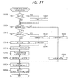
- Figure 12 is a flow chart showing the subroutine for the calculation.
- the program begins in S600 in which a timer (down-counter) tKERF is set with a predetermined value #TMKERF (illustrated in Figures 4 and 7) and starts time measurement.
- a timer down-counter
- the program then proceeds to S602 in which the OFF-side gradually decreasing pressure dQKERF is calculated in the manner shown there, and to S604 in which the calculated OFF-side gradually-decreasing pressure dQKERF is subtracted from the OFF-side clutch pressure QATOF to correct the same.
- the volume of the mapped data can be decreased and the system can determine the initial value of the OFF-side clutch pressure QATOF appropriately so as to effectively decrease the shift shock experienced by the vehicle occupant, irrespectively of the change of the throttle opening TH. Further, by decreasing the OFF-side clutch pressure gradually for a predetermined period of time #TMKIRS, it can reduce the shift shock effectively.
- the embodiment is thus configured to have a system for controlling an automatic transmission (T) of a vehicle (1) having an input shaft (MS) connected to an internal combustion engine (E) mounted on the vehicle and an output shaft (CS) connected to driven wheels (W) of the vehicle, the transmission transmitting input torque, through any of frictional engaging elements (Cn), generated by the engine and inputted by the input shaft to the driven wheels by the output shaft, in accordance with predetermined shift scheduling (S10) defining a target gear (SH, GB) based on detected operating conditions of the vehicle and the engine, including; hydraulic pressure control circuit (O) for supplying hydraulic pressure to the frictional engaging elements based on at least the calculated hydraulic pressure (QATON).
- T automatic transmission
- MS input shaft
- E internal combustion engine
- CS driven wheels
- the system includes: operating condition detecting means (60, 62, 56, 80) for detecting the operating conditions of the vehicle and the engine including at least an engine speed (NE); input shaft rotational speed detecting means (64, 80) for detecting an input shaft rotational speed (NM) inputted to the transmission (T); first torque calculating means (80, S20, S102, S200 - S204) for calculating an a first torque (TEPBK, QKIRS) to be inputted to the transmission (T) based on at least the detected operating conditions and the input shaft rotational speed (NM); second torque calculating means (80, S20, S106, S300, S302) for calculating a second torque (dTQKIRI) necessary for advancing a torque necessary for advancing shifting in the transmission based on at least the detected operating conditions and the input shaft rotational speed (NM), when the shifting is downshifting; and desired value calculating means (80, S20, S10, S108-S118" S304, S400 - 402, S500 -
- the desired value calculating means calculates the desired value (TQOF) corresponding to be the first torque (TEPBK) when the shifting begins and to be decreased with respect to time after the shifting begins (S200 - S204, S300 - S304). With this, it can determine the initial value of the desired pressure to be supplied to a frictional engaging element such as a hydraulic clutch appropriately so as to decrease the shift shock more effectively.
- the desired value calculating means calculates the desired value (TQOF) to be decreased with respect to time for a predetermined period of time (TMKIRC) after the shifting begins (S200- S204, S300 - S304). With this, it can determine the initial value of the desired pressure to be supplied to a frictional engaging element such as a hydraulic clutch appropriately so as to decrease the shift shock more effectively.
- the first torque calculating means includes; engine speed discriminating means (80, S20, S102, S200) for discriminating whether the detected engine speed (NE) is less than a predetermined speed (#NEKIRS); and when the detected engine speed is discriminated to be less than the predetermined value, calculates the first torque to be a predetermined value (#QKIRS, S204).
- the transmission has a torque converter (12) and the first torque calculating means includes engine torque calculating means (80, S20, S102, S200 - S204) for calculating an engine torque (TEPB) generated by the engine (E) in accordance with a predetermined characteristics based on at least an engine speed (NE) and an engine load (PBA) of the detected operating conditions; inertial torque calculating means (80, S20, S102, S200 - S204) for calculating a parameter (DTEI) indicative of an inertia torque used raising the engine speed (NE) based on the engine speed; and torque converter torque ratio calculating means (80, S20, S102, S200-S204) for calculating a torque ratio (KTR, ETR) of the torque converter (12); and calculates the input torque (TEPBK) based on at least the calculated engine torque (TEPB), the calculated parameter (DTEI) and the calculated torque ratio (KTR). With this, it can determine the initial value of the desired pressure to be supplied to a friction
- a system for controlling an automatic transmission of a vehicle wherein the initial value of the desired pressure to be supplied to a hydraulic clutch for the current gear now being engaged is determined appropriately, when conducting a power-on downshifting, so as to decrease the shift shock experienced by the vehicle occupant effectively, irrespectively of the change in he throttle opening, while ensuring to reduce the volume of the mapped data.
Landscapes
- Engineering & Computer Science (AREA)
- General Engineering & Computer Science (AREA)
- Physics & Mathematics (AREA)
- Fluid Mechanics (AREA)
- Mechanical Engineering (AREA)
- Control Of Transmission Device (AREA)
Claims (4)
- System zum Steuern/Regeln eines Automatikgetriebes (T) eines Fahrzeugs (1) mit einer Eingangswelle (MS), die mit einem an dem Fahrzeug angebrachten Verbrennungsmotor (E) verbunden ist, und einer Ausgangswelle (CS), die mit angetriebenen Rädern (W) des Fahrzeugs verbunden ist, wobei das Getriebe ein durch den Motor erzeugtes und durch die Eingangswelle eingeleitetes Eingangsdrehmoment durch beliebige von Reibeingriffselementen (Cn) durch die Ausgangswelle an die angetriebenen Räder überträgt, und zwar nach Maßgabe eines vorbestimmte Schaltschemas (S10), welches einen Sollgang (SH, GB) auf Grundlage erfasster Betriebsbedingungen des Fahrzeugs und des Motors definiert, wobei das System umfasst:eine Hydraulikdruck-Steuer/Regelschaltung (O) zum Zuführen von Hydraulikdruck zu den Reibeingriffselementen auf Grundlage wenigstens des berechneten Hydraulikdrucks (QATON),ein Betriebszustand-Erfassungsmittel (60, 62, 56, 80) zum Erfassen der Betriebsbedingungen des Fahrzeugs und des Motors einschließliche wenigstens einer Motordrehzahl (NE),ein Eingangswellendrehzahl-Erfassungsmittel (64, 80) zum Erfassen einer in das Getriebe (T) eingeleiteten Eingangswellendrehzahl (NM), ein erstes Drehmoment-Berechnungsmittel (80, S20, S102, S200-S204) zum Berechnen eines ersten Drehmoments (TEPBK, QKIRS), das in das Getriebe eingeleitet werden soll, und zwar auf Grundlage wenigstens der erfassten Betriebsbedingungen und der Eingangswellendrehzahl (NM),ein zweites Drehmoment-Berechnungsmittel (80, S20, S106, S300, S302) zum Berechnen eines zweiten Drehmoments (dTQKIRI), das zum Weitergeben eines zum Fortführen des Schaltens in dem Getriebe erforderlichen Drehmoments erforderlich ist, und zwar auf Grundlage wenigstens der erfassten Betriebsbedingungen und der Eingangswellendrehzahl (NM), wenn das Schalten ein Zurückschalten ist, und ein Berechnungsmittel für einen gewünschten Wert (80, S20, S10, S108-S118, S304, S400-S402, S500-S528, S600-S604) zum Berechnen eines gewünschten Werts (TQOF(qof1,QATOF)), der einem der gerade im Eingriff befindlichen Reibeingriffselemente zuzuführen ist, wobei die Hydraulikdruck-Steuer/Regelschaltung (O) dem einen der Reibeingriffselemente Hydraulikdruck zuführt, und zwar auf Grundlage wenigstens des berechneten gewünschten Werts (QATON),dadurch gekennzeichnet, dass
das Berechnungsmittel für den gewünschten Wert (80, S20, S10, S108-S118, S304, S400-S402, S500-S528, S600-S604) den gewünschten Wert (TQOF(qof1,QATOF)) auf Grundlage einer Differenz berechnet, die erhalten wird durch Subtrahieren des zweiten Drehmoments (dTQKIRI) von dem ersten Drehmoment (TEPBK), und dass das erste Drehmoment-Berechnungmittel (80, S20, S106, S300,S302) ein Motordrehzahl-Diskriminierungsmittel (80, S20, S102, S200) enthält zum Diskriminieren, ob die erfasste Motordrehzahl (NE) kleiner ist als eine vorbestimmte Drehzahl (#NEKIRS),
und dann, wenn die erfasste Motordrehzahl als kleiner als der vorbestimmte Wert diskriminiert wird, das erste Drehmoment als einen vorbestimmten Wert (#QKIRS, S204) berechnet. - System nach Anspruch 1, wobei das Berechnungsmittel für den gewünschten Wert den gewünschten Wert (TQOF) als beim Beginn des Schaltens dem ersten Drehmoment (TEPBK) entsprechend und nach dem Beginn des Schaltens als mit der Zeit abnehmend berechnet (S200-S204, S300-S304).
- System nach Anspruch 2, wobei das Berechnungsmittel für den gewünschten Wert den gewünschten Wert (TQOF) nach dem Beginn des Schaltens als über eine vorbestimmte Zeitdauer (TMKIRC) hinweg mit der Zeit abnehmend berechnet (S200-S204, S300-S304).
- System nach einem der Ansprüche 1 bis 3, wobei das Getriebe einen Drehmomentwandler (12) aufweist und das erste Drehmoment-Berechnungsmittel umfasst:ein Motordrehmoment-Berechnungsmittel (80, S20, S102, S200-S204) zum Berechnen eines durch den Motor (E) erzeugten Motordrehmoments (TEPB) nach Maßgabe einer vorbestimmten Charakteristik, und zwar auf Grundlage wenigstens der Motordrehzahl (NE) und einer Motorlast (PBA) der erfassten Betriebsbedingungen,ein Trägheitsdrehmoment-Berechnungsmittel (80,S20, S102, S200-S204) zum Berechnen eines Parameters (DTEI), der ein zur Erhöhung der Motordrehzahl (NE) verwendetes Trägheitsdrehmoment anzeigt, und zwar auf Grundlage der Motordrehzahl, undein Drehmomentwandlerdrehmomentverhältnis-Berechnungsmittel (80, S20, S102, S200-S204), zum Berechnen eines Drehmomentverhältnisses (KTR, ETR) des Drehmomentwandlers (12),und wobei das erste Drehmoment-Berechnungsmittel das Eingangsdrehmoment (TEPBK) auf Grundlage wenigstens des erfassten Motordrehmoments (TEPB), des erfassten Parameters (DTEI) und des berechneten Drehmomentverhältnisses (KTR) berechnet.
Applications Claiming Priority (2)
| Application Number | Priority Date | Filing Date | Title |
|---|---|---|---|
| JP35089399 | 1999-12-09 | ||
| JP35089399A JP3623903B2 (ja) | 1999-12-09 | 1999-12-09 | 自動変速機の制御装置 |
Publications (3)
| Publication Number | Publication Date |
|---|---|
| EP1106873A2 EP1106873A2 (de) | 2001-06-13 |
| EP1106873A3 EP1106873A3 (de) | 2004-03-24 |
| EP1106873B1 true EP1106873B1 (de) | 2006-09-13 |
Family
ID=18413618
Family Applications (1)
| Application Number | Title | Priority Date | Filing Date |
|---|---|---|---|
| EP00126972A Expired - Lifetime EP1106873B1 (de) | 1999-12-09 | 2000-12-08 | Steuerung für automatische Fahrzeuggetriebe |
Country Status (4)
| Country | Link |
|---|---|
| US (1) | US6554739B2 (de) |
| EP (1) | EP1106873B1 (de) |
| JP (1) | JP3623903B2 (de) |
| DE (1) | DE60030663T2 (de) |
Families Citing this family (9)
| Publication number | Priority date | Publication date | Assignee | Title |
|---|---|---|---|---|
| US6692409B2 (en) * | 2001-02-28 | 2004-02-17 | Kubota Corporation | Hydraulic change speed system for a working vehicle |
| JP4400617B2 (ja) * | 2006-12-15 | 2010-01-20 | トヨタ自動車株式会社 | パワートレーンの制御装置、制御方法、その方法を実現させるプログラムおよびそのプログラムを記録した記録媒体 |
| JP2008180320A (ja) * | 2007-01-25 | 2008-08-07 | Hitachi Ltd | 自動変速機の制御装置および制御方法 |
| JP4787293B2 (ja) * | 2008-06-19 | 2011-10-05 | ジヤトコ株式会社 | 自動変速機の変速制御装置 |
| US8510003B2 (en) * | 2009-04-09 | 2013-08-13 | Ford Global Technologies, Llc | Closed-loop torque phase control for shifting automatic transmission gear ratios based on friction element load estimation |
| JP5374434B2 (ja) * | 2010-04-08 | 2013-12-25 | 本田技研工業株式会社 | 自動変速機の制御装置 |
| US8630777B2 (en) * | 2011-05-06 | 2014-01-14 | GM Global Technology Operations LLC | System and method for model-based neutral idle clutch control |
| JP6617732B2 (ja) * | 2017-02-17 | 2019-12-11 | トヨタ自動車株式会社 | 車両の変速制御装置 |
| CN114491412B (zh) * | 2022-01-24 | 2024-05-24 | 一汽解放汽车有限公司 | 一种换挡数据统计方法 |
Family Cites Families (16)
| Publication number | Priority date | Publication date | Assignee | Title |
|---|---|---|---|---|
| JP3013591B2 (ja) * | 1992-04-14 | 2000-02-28 | 日産自動車株式会社 | 自動変速機の変速制御装置 |
| JPH0642616A (ja) * | 1992-05-22 | 1994-02-18 | Volkswagen Ag <Vw> | 多段自動変速機の切換時の切換快適性を高めるための制御および調整方法 |
| JPH0672187A (ja) * | 1992-05-28 | 1994-03-15 | Mitsubishi Electric Corp | 自動変速機付車両用エンジン制御装置及びその制御方法 |
| DE69333608T2 (de) * | 1992-09-16 | 2005-09-15 | Hitachi, Ltd. | Getriebesteuerung für ein Fahrzeug |
| JP3445291B2 (ja) * | 1992-10-13 | 2003-09-08 | 株式会社日立製作所 | 駆動トルク制御装置 |
| EP0654623B1 (de) * | 1993-11-22 | 1999-08-18 | Mazda Motor Corporation | Hydraulische Steuerung für Automatikgetriebe |
| JP3350201B2 (ja) * | 1994-02-14 | 2002-11-25 | 株式会社日立製作所 | トルクフィードバック変速制御装置および方法 |
| KR960013764A (ko) * | 1994-10-26 | 1996-05-22 | 가나이 쯔도무 | 파워트레인 제어장치 |
| JP3246863B2 (ja) * | 1996-03-15 | 2002-01-15 | 株式会社日立製作所 | 自動変速機の制御装置 |
| JPH09287654A (ja) * | 1996-04-19 | 1997-11-04 | Aisin Aw Co Ltd | 自動変速機の制御装置 |
| US5846161A (en) * | 1996-12-03 | 1998-12-08 | Caterpillar Inc. | Control system for an automatic transmission having shift points based on part throttle positions which are used when engine speed is lowered below an adjustable minimum engine speed setting |
| US6438479B1 (en) * | 1997-12-29 | 2002-08-20 | Hitachi, Ltd. | Control apparatus for an automatic transmission of a vehicle and method |
| JPH10243502A (ja) * | 1997-02-26 | 1998-09-11 | Aisin Aw Co Ltd | 車両用駆動装置の制御装置 |
| DE19725513A1 (de) * | 1997-06-17 | 1998-12-24 | Zahnradfabrik Friedrichshafen | Verfahren zur Verminderung des Schaltrucks beim Gangauslegen |
| JP3696380B2 (ja) * | 1997-08-27 | 2005-09-14 | 本田技研工業株式会社 | シフトダウン制御装置 |
| US6231479B1 (en) * | 1999-10-27 | 2001-05-15 | Ford Global Technologies, Inc. | Closed-loop electronic controller for applying transmission friction clutches |
-
1999
- 1999-12-09 JP JP35089399A patent/JP3623903B2/ja not_active Expired - Fee Related
-
2000
- 2000-12-08 EP EP00126972A patent/EP1106873B1/de not_active Expired - Lifetime
- 2000-12-08 DE DE60030663T patent/DE60030663T2/de not_active Expired - Lifetime
- 2000-12-08 US US09/731,795 patent/US6554739B2/en not_active Expired - Lifetime
Also Published As
| Publication number | Publication date |
|---|---|
| EP1106873A3 (de) | 2004-03-24 |
| DE60030663T2 (de) | 2007-10-04 |
| US6554739B2 (en) | 2003-04-29 |
| JP2001165292A (ja) | 2001-06-19 |
| EP1106873A2 (de) | 2001-06-13 |
| JP3623903B2 (ja) | 2005-02-23 |
| US20010003722A1 (en) | 2001-06-14 |
| DE60030663D1 (de) | 2006-10-26 |
Similar Documents
| Publication | Publication Date | Title |
|---|---|---|
| EP1347195B1 (de) | Doppelkupplungsgetriebe | |
| CA2327861C (en) | Control system for automatic vehicle transmissions | |
| US6346063B1 (en) | Vehicle transmission shift control for engagement of frictional coupling device so as to first raise transmission input speed above synchronizing speed | |
| US6547698B2 (en) | Control system for automatic vehicle transmissions | |
| EP1106875B1 (de) | Steuerung für automatische Fahrzeuggetriebe | |
| US6390949B1 (en) | Apparatus for controlling frictional coupling device to effect vehicle transmission upshift while accelerator pedal is not in operation | |
| EP1983229B1 (de) | Steuersystem für automatische Fahrzeuggetriebe | |
| EP1106873B1 (de) | Steuerung für automatische Fahrzeuggetriebe | |
| AU630833B2 (en) | Double transition upshift control method for an automatic transmission | |
| US6889130B2 (en) | Shift control system for automatic transmission | |
| JPH08233088A (ja) | 車両用油圧作動式変速機の油圧制御装置 | |
| EP0573010B1 (de) | Steuerungseinrichtung für ein automatisches Kraftfahrzeuggetriebe | |
| JP4215186B2 (ja) | 車両用自動変速機の変速制御方法 | |
| US5376058A (en) | Arrangement for control of line fluid pressure in automatic transmission | |
| JP2001165300A (ja) | 自動変速機の制御装置 | |
| JPH02292566A (ja) | 自動変速機の油圧制御装置 | |
| JP5162547B2 (ja) | 自動変速機の制御装置 | |
| JPH0751981B2 (ja) | パワートレーンの変速ショック軽減用総合制御装置 | |
| JP2012057784A (ja) | 自動変速機の制御装置 | |
| JPH0658395A (ja) | 自動変速機の変速制御装置 | |
| JP2001165291A (ja) | 自動変速機の制御装置 | |
| JP2001165301A (ja) | 自動変速機の制御装置 |
Legal Events
| Date | Code | Title | Description |
|---|---|---|---|
| PUAI | Public reference made under article 153(3) epc to a published international application that has entered the european phase |
Free format text: ORIGINAL CODE: 0009012 |
|
| 17P | Request for examination filed |
Effective date: 20001208 |
|
| AK | Designated contracting states |
Kind code of ref document: A2 Designated state(s): AT BE CH CY DE DK ES FI FR GB GR IE IT LI LU MC NL PT SE TR |
|
| AX | Request for extension of the european patent |
Free format text: AL;LT;LV;MK;RO;SI |
|
| PUAL | Search report despatched |
Free format text: ORIGINAL CODE: 0009013 |
|
| AK | Designated contracting states |
Kind code of ref document: A3 Designated state(s): AT BE CH CY DE DK ES FI FR GB GR IE IT LI LU MC NL PT SE TR |
|
| AX | Request for extension of the european patent |
Extension state: AL LT LV MK RO SI |
|
| RIC1 | Information provided on ipc code assigned before grant |
Ipc: 7F 16H 61/06 A Ipc: 7F 16H 59/42 B |
|
| AKX | Designation fees paid |
Designated state(s): DE GB |
|
| GRAP | Despatch of communication of intention to grant a patent |
Free format text: ORIGINAL CODE: EPIDOSNIGR1 |
|
| GRAS | Grant fee paid |
Free format text: ORIGINAL CODE: EPIDOSNIGR3 |
|
| GRAA | (expected) grant |
Free format text: ORIGINAL CODE: 0009210 |
|
| AK | Designated contracting states |
Kind code of ref document: B1 Designated state(s): DE GB |
|
| REG | Reference to a national code |
Ref country code: GB Ref legal event code: FG4D |
|
| REF | Corresponds to: |
Ref document number: 60030663 Country of ref document: DE Date of ref document: 20061026 Kind code of ref document: P |
|
| PLBE | No opposition filed within time limit |
Free format text: ORIGINAL CODE: 0009261 |
|
| STAA | Information on the status of an ep patent application or granted ep patent |
Free format text: STATUS: NO OPPOSITION FILED WITHIN TIME LIMIT |
|
| 26N | No opposition filed |
Effective date: 20070614 |
|
| PGFP | Annual fee paid to national office [announced via postgrant information from national office to epo] |
Ref country code: GB Payment date: 20131204 Year of fee payment: 14 |
|
| REG | Reference to a national code |
Ref country code: DE Ref legal event code: R084 Ref document number: 60030663 Country of ref document: DE |
|
| REG | Reference to a national code |
Ref country code: GB Ref legal event code: 746 Effective date: 20140813 |
|
| REG | Reference to a national code |
Ref country code: DE Ref legal event code: R084 Ref document number: 60030663 Country of ref document: DE Effective date: 20140821 |
|
| GBPC | Gb: european patent ceased through non-payment of renewal fee |
Effective date: 20141208 |
|
| PG25 | Lapsed in a contracting state [announced via postgrant information from national office to epo] |
Ref country code: GB Free format text: LAPSE BECAUSE OF NON-PAYMENT OF DUE FEES Effective date: 20141208 |
|
| PGFP | Annual fee paid to national office [announced via postgrant information from national office to epo] |
Ref country code: DE Payment date: 20151201 Year of fee payment: 16 |
|
| REG | Reference to a national code |
Ref country code: DE Ref legal event code: R119 Ref document number: 60030663 Country of ref document: DE |
|
| PG25 | Lapsed in a contracting state [announced via postgrant information from national office to epo] |
Ref country code: DE Free format text: LAPSE BECAUSE OF NON-PAYMENT OF DUE FEES Effective date: 20170701 |