EP1107443A1 - Verfahren und Vorrichtung zur Steuerung einer elektromotorisch betriebenen Rolle - Google Patents
Verfahren und Vorrichtung zur Steuerung einer elektromotorisch betriebenen Rolle Download PDFInfo
- Publication number
- EP1107443A1 EP1107443A1 EP00125805A EP00125805A EP1107443A1 EP 1107443 A1 EP1107443 A1 EP 1107443A1 EP 00125805 A EP00125805 A EP 00125805A EP 00125805 A EP00125805 A EP 00125805A EP 1107443 A1 EP1107443 A1 EP 1107443A1
- Authority
- EP
- European Patent Office
- Prior art keywords
- motor
- brake
- delay circuit
- electromagnetic brake
- electromagnetic
- Prior art date
- Legal status (The legal status is an assumption and is not a legal conclusion. Google has not performed a legal analysis and makes no representation as to the accuracy of the status listed.)
- Granted
Links
- 238000000034 method Methods 0.000 title claims description 12
- 239000000758 substrate Substances 0.000 claims abstract description 6
- 230000007423 decrease Effects 0.000 claims description 5
- 238000005299 abrasion Methods 0.000 abstract description 4
- 230000004913 activation Effects 0.000 description 4
- 238000007796 conventional method Methods 0.000 description 3
- 230000003213 activating effect Effects 0.000 description 1
- 238000010586 diagram Methods 0.000 description 1
- 230000000694 effects Effects 0.000 description 1
- 230000035939 shock Effects 0.000 description 1
- 238000004904 shortening Methods 0.000 description 1
Images
Classifications
-
- B—PERFORMING OPERATIONS; TRANSPORTING
- B65—CONVEYING; PACKING; STORING; HANDLING THIN OR FILAMENTARY MATERIAL
- B65G—TRANSPORT OR STORAGE DEVICES, e.g. CONVEYORS FOR LOADING OR TIPPING, SHOP CONVEYOR SYSTEMS OR PNEUMATIC TUBE CONVEYORS
- B65G23/00—Driving gear for endless conveyors; Belt- or chain-tensioning arrangements
- B65G23/02—Belt- or chain-engaging elements
- B65G23/04—Drums, rollers, or wheels
- B65G23/08—Drums, rollers, or wheels with self-contained driving mechanisms, e.g. motors and associated gearing
-
- B—PERFORMING OPERATIONS; TRANSPORTING
- B65—CONVEYING; PACKING; STORING; HANDLING THIN OR FILAMENTARY MATERIAL
- B65G—TRANSPORT OR STORAGE DEVICES, e.g. CONVEYORS FOR LOADING OR TIPPING, SHOP CONVEYOR SYSTEMS OR PNEUMATIC TUBE CONVEYORS
- B65G13/00—Roller-ways
- B65G13/075—Braking means
-
- B—PERFORMING OPERATIONS; TRANSPORTING
- B65—CONVEYING; PACKING; STORING; HANDLING THIN OR FILAMENTARY MATERIAL
- B65G—TRANSPORT OR STORAGE DEVICES, e.g. CONVEYORS FOR LOADING OR TIPPING, SHOP CONVEYOR SYSTEMS OR PNEUMATIC TUBE CONVEYORS
- B65G39/00—Rollers, e.g. drive rollers, or arrangements thereof incorporated in roller-ways or other types of mechanical conveyors
- B65G39/02—Adaptations of individual rollers and supports therefor
-
- H—ELECTRICITY
- H02—GENERATION; CONVERSION OR DISTRIBUTION OF ELECTRIC POWER
- H02P—CONTROL OR REGULATION OF ELECTRIC MOTORS, ELECTRIC GENERATORS OR DYNAMO-ELECTRIC CONVERTERS; CONTROLLING TRANSFORMERS, REACTORS OR CHOKE COILS
- H02P3/00—Arrangements for stopping or slowing electric motors, generators, or dynamo-electric converters
- H02P3/02—Details of stopping control
- H02P3/04—Means for stopping or slowing by a separate brake, e.g. friction brake or eddy-current brake
-
- H—ELECTRICITY
- H02—GENERATION; CONVERSION OR DISTRIBUTION OF ELECTRIC POWER
- H02P—CONTROL OR REGULATION OF ELECTRIC MOTORS, ELECTRIC GENERATORS OR DYNAMO-ELECTRIC CONVERTERS; CONTROLLING TRANSFORMERS, REACTORS OR CHOKE COILS
- H02P6/00—Arrangements for controlling synchronous motors or other dynamo-electric motors using electronic commutation dependent on the rotor position; Electronic commutators therefor
- H02P6/24—Arrangements for stopping
Definitions
- the present invention relates to a method and a device for controlling a motor driven roller, which is powered by a brushless motor equipped with a brake mechanism.
- a motor driven roller can be used, for example, in a conveyor, in particular a conveyor that is repeatedly switched on and off.
- a motor driven roller for a conveyor is usually stopped by an electric brake. What is stopped, however, is only the rotation of the roller itself. The conveyor itself can be moved easily by an external force, etc. On the other hand, in a mechanism in which the conveyor is stopped mechanically using an electromagnetic brake only, the brake pad is subjected to friction, which causes abrasion and shortens the life of the brake pad. In order to solve these problems, a number of methods have been devised to increase the electric brake power. Another method that has been devised for ensuring the stopping position uses both an electric inverter brake and a physical electromagnetic brake. In such a conventional method for controlling a motor driven roller for a conveyor using both an electric brake and an electromagnetic brake, the electric brake and the electromagnetic brake are activated at the same time.
- the present invention aims at solving these problems associated with the conventional methods by using a simple method to delay the activation timing of the electromagnetic brake until after the revolution of the brushless motor is reduced, thereby providing an economical motor driven roller that can be used over an extended period of time because the brake parts wear less.
- a motor driven roller powered by a brushless motor is provided with a built-in electromagnetic brake, and a delay circuit is provided in a drive-controlling device for the motor.
- the delay circuit uses the motor pulse detected by a motor driver. When a stop signal is input, the motor pulse rate declines. This decline of the motor pulse rate is detected to activate an electromagnetic brake. Because the motor pulse can be detected by the motor driver, it is sufficient to mount the delay circuit for activating the electromagnetic brake on the driver substrate of the motor driver; there is no need to provide a special delay circuit device.
- the electromagnetic brake can be activated only after the electric brake has been activated and the revolution of the brushless motor has been sufficiently reduced. This minimizes the abrasion of the brake parts. Accordingly, the present invention is quite effective for use with a belt conveyor that needs to be switched on and off frequently.
- the delay circuit employed in the present invention uses the motor pulse that is detected by the motor driver, the present invention can be embodied by simply adding the delay circuit to the motor substrate. Therefore, there is no need to install a special delay circuit device. This makes it possible to embody the present invention simply and inexpensively.
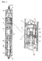
- FIG. 2 is a longitudinal section of a motor driven roller.
- This roller includes a brushless motor 2 inside the outer casing 1.
- the rotation of the brushless motor 2 is transmitted to the outer casing from the output part 2b by first reducing the rotation of the rotor shaft 2a via the reduction gear 3.
- the outer casing 1 which is linked to the rotor shaft, rotates with respect to the fixed shaft 4, which is attached to one part of the conveyor.
- a bearing 5 is mounted to smooth the rotation.
- FIG. 2 also shows an enlarged view of a section of the electromagnetic brake.
- This electromagnetic brake has an inner disk 8 at the tip of the rotor 2a.
- the inner disk 8 is sandwiched by an outer disk 9, which is a fixed part, and an electromagnetic plate 10, which is movable in the axial direction.
- the electromagnetic plate 10 is constantly pressed against the inner disk 8, which functions as a brake pad, by a spring 11. When the inner disk 8 is gripped by the outer disk 9 and the electromagnetic plate 10, a braking condition takes effect.
- the electromagnetic plate 10 which is movable in the axial direction, is designed to be attracted by the electromagnetic coil 12 of the electromagnetic brake 7.
- the electromagnetic brake works by the resilience of the spring 11.
- the electromagnetic plate 10 is attracted to the electromagnetic coil 12, resisting the resilience of the spring 11, thereby releasing the brake.
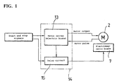
- FIG. 1 shows a schematic drawing of the motor-roller-controlling device with the brushless motor 2 built in.
- a transistor When a stop signal is transmitted, a transistor is activated, which in turn activates an electric brake to slow down the brushless motor 2. Activation of an electric brake using a transistor is a widely used technique in a brushless motor.
- the motor pulse rate which inevitably reflects the revolution of the brushless motor 2, is fed back to the motor driver 13.
- the driver substrate 14, on which the motor driver is mounted is also provided with a delay circuit 15 .
- the delay circuit 15 uses the motor pulse rate fed back to the motor driver to detect the decline of the motor pulse rate. In other words, after detecting that the motor pulse rate has sufficiently declined after the stop signal has been given, the electric current to the electromagnetic coil 12 of the electromagnetic brake 7 is cut off. When the electric current to the electric magnetic coil 12 is cut off, the attraction of the electromagnetic plate 10 by the electromagnetic coil is released, and the electromagnetic plate 10 is pressed against the inner disk 8 by the resilience of the spring 11. In other words, the electromagnetic brake 7 is activated, and the rotation of the brushless motor 2 is completely stopped.
- the delay circuit 15 may activate the electromagnetic brake by either detecting the declining trend of the motor pulse or by confirming the cessation of the motor pulse.
- the roller can be stopped in a short period of time. According to this method, because the electromagnetic brake is activated after the electric brake is activated, the motor roller can be stopped with little shock, making it possible to avoid sudden friction with the inner disk 8, which is a friction part.
- the time to a complete halt is determined by the characteristic of the electric brake. In this case, the time to a complete halt is longer than in the above case.
- the delay circuit 15 of the present invention need only consist of a circuit that detects changes in the motor pulse rate on the driver substrate 14 on which the motor driver is mounted, and there is no need to install a timer, an electromagnetic valve or other special delay circuits on the control board. This makes it possible to embody the present invention simply and inexpensively.
Landscapes
- Engineering & Computer Science (AREA)
- Mechanical Engineering (AREA)
- Power Engineering (AREA)
- Control Of Conveyors (AREA)
- Rollers For Roller Conveyors For Transfer (AREA)
- Control Of Motors That Do Not Use Commutators (AREA)
- Connection Of Motors, Electrical Generators, Mechanical Devices, And The Like (AREA)
Applications Claiming Priority (2)
| Application Number | Priority Date | Filing Date | Title |
|---|---|---|---|
| JP33996799 | 1999-11-30 | ||
| JP33996799A JP2001161091A (ja) | 1999-11-30 | 1999-11-30 | モータローラの制御方法 |
Publications (2)
| Publication Number | Publication Date |
|---|---|
| EP1107443A1 true EP1107443A1 (de) | 2001-06-13 |
| EP1107443B1 EP1107443B1 (de) | 2003-04-09 |
Family
ID=18332474
Family Applications (1)
| Application Number | Title | Priority Date | Filing Date |
|---|---|---|---|
| EP00125805A Expired - Lifetime EP1107443B1 (de) | 1999-11-30 | 2000-11-24 | Verfahren und Vorrichtung zur Steuerung einer elektromotorisch betriebenen Rolle |
Country Status (4)
| Country | Link |
|---|---|
| US (1) | US6456032B2 (de) |
| EP (1) | EP1107443B1 (de) |
| JP (1) | JP2001161091A (de) |
| DE (1) | DE60002027T2 (de) |
Cited By (9)
| Publication number | Priority date | Publication date | Assignee | Title |
|---|---|---|---|---|
| EP1172312A1 (de) * | 2000-07-14 | 2002-01-16 | Itoh Electric Co., Ltd. | Steuerungsverfahren einer Rolle mit eingebautem Motor |
| WO2004107531A3 (de) * | 2003-05-30 | 2005-06-09 | Siemens Ag | Rollen und rollenmotoren |
| FR2870530A1 (fr) * | 2004-05-18 | 2005-11-25 | David Sas Soc Par Actions Simp | Dispositif d'arret de fonctionnement pour convoyeur a rouleaux motorise de charges |
| US7374036B2 (en) | 2006-02-08 | 2008-05-20 | Eisenmann Anlagenbau Gmbh & Co. Kg | Roller conveyor |
| US7565965B2 (en) | 2006-02-08 | 2009-07-28 | Eisenmann Anlagenbau Gmbh & Co. Kg. | Set of roller conveyors |
| US7673737B2 (en) | 2006-02-08 | 2010-03-09 | Eisenmann Anlagenbau Gmbh & Co. Kg | Roller conveyor |
| CN101081659B (zh) * | 2006-05-29 | 2011-01-26 | 艾森曼机械制造有限及两合公司 | 辊道系统及其控制方法 |
| AT516925A1 (de) * | 2015-03-12 | 2016-09-15 | Tgw Mechanics Gmbh | Fördereinrichtung mit verbesserter Verdrahtung von Antriebsmotor und Bremse einer Förderrolle sowie Betriebsverfahren dafür |
| WO2023174997A1 (en) * | 2022-03-16 | 2023-09-21 | Interroll Holding Ag | Brake roller, roller conveyor and method of installation of a roller conveyor |
Families Citing this family (14)
| Publication number | Priority date | Publication date | Assignee | Title |
|---|---|---|---|---|
| JP3740470B2 (ja) * | 2003-02-10 | 2006-02-01 | 住友重機械工業株式会社 | 減速機付のdcブラシレスモータ |
| KR100676323B1 (ko) * | 2003-07-08 | 2007-01-30 | 삼성전자주식회사 | 3상모터 제어장치 |
| JP2005054843A (ja) * | 2003-08-01 | 2005-03-03 | Fanuc Ltd | ブレーキ装置 |
| EP2177413B1 (de) * | 2004-07-15 | 2015-02-25 | Hitachi, Ltd. | Fahrzeugsteuerungssystem |
| DE102005047531A1 (de) * | 2005-10-04 | 2007-04-12 | Eisenmann Anlagenbau Gmbh & Co. Kg | Rollenleiste zum Aufbau eines Rollenbahnförderers |
| US8149346B2 (en) * | 2005-10-14 | 2012-04-03 | Semiconductor Energy Laboratory Co., Ltd. | Display device and manufacturing method thereof |
| KR100788504B1 (ko) | 2006-04-05 | 2008-01-02 | 주식회사 한국 오에프에이시스템 | 컨베이어 롤러 자동감속장치 |
| JP2008022678A (ja) * | 2006-07-14 | 2008-01-31 | Matsushita Electric Ind Co Ltd | モータ駆動装置及びモータ制動方法 |
| US20100025197A1 (en) * | 2006-11-17 | 2010-02-04 | Eisnmann Anlagenbau GmbH & Co. KG | Roller Strip for Constructing a Roller Conveyor |
| FR2938716B1 (fr) * | 2008-11-14 | 2011-07-22 | Hispano Suiza Sa | Systeme de frein electrique a pertes magnetiques |
| US9679929B2 (en) | 2012-10-12 | 2017-06-13 | Samsung Electronics Co., Ltd. | Binary image sensors including quantum dots and unit pixels thereof |
| CN103516126A (zh) * | 2013-09-21 | 2014-01-15 | 苏州蓝王机床工具科技有限公司 | 一种制动电机 |
| JP7659475B2 (ja) * | 2021-09-13 | 2025-04-09 | 株式会社マキタ | 電動運搬車 |
| EP4175129A1 (de) * | 2021-10-29 | 2023-05-03 | Itoh Denki Co., Ltd. | Motoreinheit für einen motor mit einer rolle, getriebemotor und herstellungsverfahren dafür |
Citations (4)
| Publication number | Priority date | Publication date | Assignee | Title |
|---|---|---|---|---|
| US3713521A (en) * | 1970-10-12 | 1973-01-30 | Takenishi Seisakusho K K | Roller provided with speed controlling mechanism for articles being conveyed on a roller conveyor |
| US4494058A (en) * | 1981-12-31 | 1985-01-15 | Burroughs Corporation | Motor control for data disc rotating systems |
| US5147020A (en) * | 1991-06-17 | 1992-09-15 | Lucas Western Inc. | Conveyor roller brake |
| EP0726643A1 (de) * | 1995-02-08 | 1996-08-14 | MAN Roland Druckmaschinen AG | Verfahren und Vorrichtung zum Bremsen eines elektrischen Hauptantriebes einer Druckmaschine |
Family Cites Families (3)
| Publication number | Priority date | Publication date | Assignee | Title |
|---|---|---|---|---|
| US5192859A (en) * | 1988-07-26 | 1993-03-09 | Kabushiki Kaisha Nippon Conlux | Card carrier in card reader |
| US5604412A (en) * | 1993-03-19 | 1997-02-18 | Nidec Corporation | Brushless motor and a control circuit thereof |
| US5587640A (en) * | 1994-09-28 | 1996-12-24 | Tetra Laval Holdings & Finance S.A. | Delayed safety braking apparatus for a servomotor control system |
-
1999
- 1999-11-30 JP JP33996799A patent/JP2001161091A/ja active Pending
-
2000
- 2000-11-24 EP EP00125805A patent/EP1107443B1/de not_active Expired - Lifetime
- 2000-11-24 DE DE60002027T patent/DE60002027T2/de not_active Expired - Lifetime
- 2000-11-29 US US09/725,670 patent/US6456032B2/en not_active Expired - Fee Related
Patent Citations (4)
| Publication number | Priority date | Publication date | Assignee | Title |
|---|---|---|---|---|
| US3713521A (en) * | 1970-10-12 | 1973-01-30 | Takenishi Seisakusho K K | Roller provided with speed controlling mechanism for articles being conveyed on a roller conveyor |
| US4494058A (en) * | 1981-12-31 | 1985-01-15 | Burroughs Corporation | Motor control for data disc rotating systems |
| US5147020A (en) * | 1991-06-17 | 1992-09-15 | Lucas Western Inc. | Conveyor roller brake |
| EP0726643A1 (de) * | 1995-02-08 | 1996-08-14 | MAN Roland Druckmaschinen AG | Verfahren und Vorrichtung zum Bremsen eines elektrischen Hauptantriebes einer Druckmaschine |
Cited By (11)
| Publication number | Priority date | Publication date | Assignee | Title |
|---|---|---|---|---|
| EP1172312A1 (de) * | 2000-07-14 | 2002-01-16 | Itoh Electric Co., Ltd. | Steuerungsverfahren einer Rolle mit eingebautem Motor |
| WO2004107531A3 (de) * | 2003-05-30 | 2005-06-09 | Siemens Ag | Rollen und rollenmotoren |
| FR2870530A1 (fr) * | 2004-05-18 | 2005-11-25 | David Sas Soc Par Actions Simp | Dispositif d'arret de fonctionnement pour convoyeur a rouleaux motorise de charges |
| US7374036B2 (en) | 2006-02-08 | 2008-05-20 | Eisenmann Anlagenbau Gmbh & Co. Kg | Roller conveyor |
| US7565965B2 (en) | 2006-02-08 | 2009-07-28 | Eisenmann Anlagenbau Gmbh & Co. Kg. | Set of roller conveyors |
| US7673737B2 (en) | 2006-02-08 | 2010-03-09 | Eisenmann Anlagenbau Gmbh & Co. Kg | Roller conveyor |
| CN101081659B (zh) * | 2006-05-29 | 2011-01-26 | 艾森曼机械制造有限及两合公司 | 辊道系统及其控制方法 |
| AT516925A1 (de) * | 2015-03-12 | 2016-09-15 | Tgw Mechanics Gmbh | Fördereinrichtung mit verbesserter Verdrahtung von Antriebsmotor und Bremse einer Förderrolle sowie Betriebsverfahren dafür |
| US10618737B2 (en) | 2015-03-12 | 2020-04-14 | Tgw Mechanics Gmbh | Conveying device with improved wiring of drive motor and brake of a conveying roller and operating method therefor |
| AT516925B1 (de) * | 2015-03-12 | 2021-08-15 | Tgw Mechanics Gmbh | Fördereinrichtung mit verbesserter Verdrahtung von Antriebsmotor und Bremse einer Förderrolle sowie Betriebsverfahren dafür |
| WO2023174997A1 (en) * | 2022-03-16 | 2023-09-21 | Interroll Holding Ag | Brake roller, roller conveyor and method of installation of a roller conveyor |
Also Published As
| Publication number | Publication date |
|---|---|
| US6456032B2 (en) | 2002-09-24 |
| US20010002099A1 (en) | 2001-05-31 |
| DE60002027D1 (de) | 2003-05-15 |
| DE60002027T2 (de) | 2004-02-19 |
| JP2001161091A (ja) | 2001-06-12 |
| EP1107443B1 (de) | 2003-04-09 |
Similar Documents
| Publication | Publication Date | Title |
|---|---|---|
| EP1107443B1 (de) | Verfahren und Vorrichtung zur Steuerung einer elektromotorisch betriebenen Rolle | |
| US6390249B2 (en) | Control method for a roller with a built-in motor | |
| US7310911B1 (en) | Automatic door opener with magnetic clutch | |
| US6612422B2 (en) | Conveyor roller assembly | |
| AU2003216868A1 (en) | Electrically actuatable vehicle brake and method for controlling an electrically actuatable vehicle brake | |
| US20040239196A1 (en) | Motor with a brake | |
| JPS6133883A (ja) | ロボツトの把持装置 | |
| WO2003050437A2 (en) | Screw actuator with locking mechanism | |
| WO2017164106A1 (ja) | 開閉体制御装置 | |
| JP6770019B2 (ja) | 複数のモータが1つの動作軸を駆動する駆動装置、及び駆動装置を備えるロボット | |
| KR20090094767A (ko) | 서보모터의 브레이크 장치 | |
| JP4864582B2 (ja) | トルク自動切替装置 | |
| EP1048905A3 (de) | Zeitgesteuerter Leistungsschalter für eine Antriebsvorrichtung | |
| JPH0523994A (ja) | ダイレクトドライブロボツトの制動装置 | |
| JPH10249760A (ja) | 産業用ロボット | |
| EP0104996B1 (de) | Bremseinrichtung für Bandaufnahmegerät mit koaxialen Spulen | |
| JP2002233176A (ja) | 電動アクチュエータ | |
| US1186188A (en) | Automatic power cut-off. | |
| US5282523A (en) | Travel limit stop for a motor driven actuator | |
| EP3425228B1 (de) | Drehmomentbegrenzeranordnung | |
| JP2002227887A (ja) | 電動アクチュエータ及び電動ブレーキ装置 | |
| JP3939573B2 (ja) | モータアクチュエータ | |
| KR100357784B1 (ko) | 급제동 안전 장치 | |
| JPS5941814B2 (ja) | 長尺材の供給位置決め装置 | |
| JP2002206621A (ja) | 電動アクチュエータ |
Legal Events
| Date | Code | Title | Description |
|---|---|---|---|
| PUAI | Public reference made under article 153(3) epc to a published international application that has entered the european phase |
Free format text: ORIGINAL CODE: 0009012 |
|
| AK | Designated contracting states |
Kind code of ref document: A1 Designated state(s): DE FR GB |
|
| AX | Request for extension of the european patent |
Free format text: AL;LT;LV;MK;RO;SI |
|
| 17P | Request for examination filed |
Effective date: 20010731 |
|
| AKX | Designation fees paid |
Free format text: DE FR GB |
|
| GRAG | Despatch of communication of intention to grant |
Free format text: ORIGINAL CODE: EPIDOS AGRA |
|
| 17Q | First examination report despatched |
Effective date: 20020507 |
|
| GRAG | Despatch of communication of intention to grant |
Free format text: ORIGINAL CODE: EPIDOS AGRA |
|
| GRAH | Despatch of communication of intention to grant a patent |
Free format text: ORIGINAL CODE: EPIDOS IGRA |
|
| GRAH | Despatch of communication of intention to grant a patent |
Free format text: ORIGINAL CODE: EPIDOS IGRA |
|
| GRAA | (expected) grant |
Free format text: ORIGINAL CODE: 0009210 |
|
| AK | Designated contracting states |
Designated state(s): DE FR GB |
|
| REG | Reference to a national code |
Ref country code: GB Ref legal event code: FG4D |
|
| ET | Fr: translation filed | ||
| PLBE | No opposition filed within time limit |
Free format text: ORIGINAL CODE: 0009261 |
|
| STAA | Information on the status of an ep patent application or granted ep patent |
Free format text: STATUS: NO OPPOSITION FILED WITHIN TIME LIMIT |
|
| 26N | No opposition filed |
Effective date: 20040112 |
|
| PGFP | Annual fee paid to national office [announced via postgrant information from national office to epo] |
Ref country code: DE Payment date: 20150123 Year of fee payment: 15 |
|
| REG | Reference to a national code |
Ref country code: FR Ref legal event code: PLFP Year of fee payment: 16 |
|
| REG | Reference to a national code |
Ref country code: DE Ref legal event code: R119 Ref document number: 60002027 Country of ref document: DE |
|
| REG | Reference to a national code |
Ref country code: FR Ref legal event code: PLFP Year of fee payment: 17 |
|
| PG25 | Lapsed in a contracting state [announced via postgrant information from national office to epo] |
Ref country code: DE Free format text: LAPSE BECAUSE OF NON-PAYMENT OF DUE FEES Effective date: 20160601 |
|
| REG | Reference to a national code |
Ref country code: FR Ref legal event code: PLFP Year of fee payment: 18 |
|
| PGFP | Annual fee paid to national office [announced via postgrant information from national office to epo] |
Ref country code: GB Payment date: 20171114 Year of fee payment: 18 |
|
| REG | Reference to a national code |
Ref country code: FR Ref legal event code: PLFP Year of fee payment: 19 |
|
| GBPC | Gb: european patent ceased through non-payment of renewal fee |
Effective date: 20181124 |
|
| PG25 | Lapsed in a contracting state [announced via postgrant information from national office to epo] |
Ref country code: GB Free format text: LAPSE BECAUSE OF NON-PAYMENT OF DUE FEES Effective date: 20181124 |
|
| PGFP | Annual fee paid to national office [announced via postgrant information from national office to epo] |
Ref country code: FR Payment date: 20191007 Year of fee payment: 20 |