EP1108260B1 - Strommundlerschaltung mit zweistufigem strom - Google Patents
Strommundlerschaltung mit zweistufigem strom Download PDFInfo
- Publication number
- EP1108260B1 EP1108260B1 EP00946885A EP00946885A EP1108260B1 EP 1108260 B1 EP1108260 B1 EP 1108260B1 EP 00946885 A EP00946885 A EP 00946885A EP 00946885 A EP00946885 A EP 00946885A EP 1108260 B1 EP1108260 B1 EP 1108260B1
- Authority
- EP
- European Patent Office
- Prior art keywords
- circuit
- current
- transformer
- primary
- dual
- Prior art date
- Legal status (The legal status is an assumption and is not a legal conclusion. Google has not performed a legal analysis and makes no representation as to the accuracy of the status listed.)
- Expired - Lifetime
Links
- 239000000696 magnetic material Substances 0.000 claims description 6
- 230000005284 excitation Effects 0.000 claims description 4
- 239000000463 material Substances 0.000 claims description 3
- 238000004804 winding Methods 0.000 description 8
- 230000001681 protective effect Effects 0.000 description 7
- 238000010586 diagram Methods 0.000 description 3
- 238000000034 method Methods 0.000 description 2
- 230000003247 decreasing effect Effects 0.000 description 1
- 230000000694 effects Effects 0.000 description 1
- 230000005294 ferromagnetic effect Effects 0.000 description 1
- 230000004907 flux Effects 0.000 description 1
- 230000005291 magnetic effect Effects 0.000 description 1
- 238000012986 modification Methods 0.000 description 1
- 230000004048 modification Effects 0.000 description 1
- 238000005549 size reduction Methods 0.000 description 1
Images


Classifications
-
- H—ELECTRICITY
- H01—ELECTRIC ELEMENTS
- H01F—MAGNETS; INDUCTANCES; TRANSFORMERS; SELECTION OF MATERIALS FOR THEIR MAGNETIC PROPERTIES
- H01F38/00—Adaptations of transformers or inductances for specific applications or functions
- H01F38/20—Instruments transformers
- H01F38/22—Instruments transformers for single phase AC
- H01F38/28—Current transformers
- H01F38/32—Circuit arrangements
-
- G—PHYSICS
- G01—MEASURING; TESTING
- G01R—MEASURING ELECTRIC VARIABLES; MEASURING MAGNETIC VARIABLES
- G01R15/00—Details of measuring arrangements of the types provided for in groups G01R17/00 - G01R29/00, G01R33/00 - G01R33/26 or G01R35/00
- G01R15/14—Adaptations providing voltage or current isolation, e.g. for high-voltage or high-current networks
- G01R15/18—Adaptations providing voltage or current isolation, e.g. for high-voltage or high-current networks using inductive devices, e.g. transformers
- G01R15/183—Adaptations providing voltage or current isolation, e.g. for high-voltage or high-current networks using inductive devices, e.g. transformers using transformers with a magnetic core
-
- H—ELECTRICITY
- H01—ELECTRIC ELEMENTS
- H01F—MAGNETS; INDUCTANCES; TRANSFORMERS; SELECTION OF MATERIALS FOR THEIR MAGNETIC PROPERTIES
- H01F27/00—Details of transformers or inductances, in general
- H01F27/34—Special means for preventing or reducing unwanted electric or magnetic effects, e.g. no-load losses, reactive currents, harmonics, oscillations, leakage fields
- H01F27/38—Auxiliary core members; Auxiliary coils or windings
-
- H—ELECTRICITY
- H01—ELECTRIC ELEMENTS
- H01F—MAGNETS; INDUCTANCES; TRANSFORMERS; SELECTION OF MATERIALS FOR THEIR MAGNETIC PROPERTIES
- H01F27/00—Details of transformers or inductances, in general
- H01F27/42—Circuits specially adapted for the purpose of modifying, or compensating for, electric characteristics of transformers, reactors, or choke coils
Definitions
- the present invention relates to a dual-rated current transformer circuit, and more particularly to a miniature dual-rated transformer circuit for use in a protective relay.
- the relay detects a condition and generates a signal to operate, for example, a trip coil in a low ampere industrial rated circuit breaker.
- a current transformer assembly is utilized to provide operating power to the trip coil.
- a single current transformer core fits within the circuit breaker and supplies a sufficient current and operating power to the trip unit circuit for a number of ampere ratings.
- US 5,150,039 discloses a single phase multi-ratio current transformer having at least two different current ratio or output levels through the appropriate wiring of its output leads without any intervention of the main current circuit of the system.
- the current transformer comprises a first current line which delivers a first current and a transformer coupled to the first current line.
- larger breakers for industrial or utility applications traditionally utilize protective relays that have their own enclosures.
- the protective relays have a source of power to operate other than from the current transformer.
- the output of the protective relay is normally a contact or solid-state device to connect the trip coil to a source of power independent from the relay.
- the current transformers are used to replicate and isolate the input current and are normally rated one ampere or five amperes.
- the current transformer must work over a large current range that includes fault current, which is much greater than rated current for protection and metering, and metering current which can be less than rated current.
- a typical current transformer for a one ampere input rating would have a twenty turn primary and a separate design for a five ampere input rating which would have four turns.
- the present invention provides a dual-rated current transformer circuit as defined in claim 1.
- One embodiment of the present invention provides a dual-rated current transformer circuit which utilizes a transformer having a reduced size.
- Another embodiment of the invention is a transformer circuit which will meet the application requirements using a typical magnetic material that has a relatively low cost.
- the number of turns can vary due to changes in the magnetic material or application.
- Still another embodiment of the invention is a transformer circuit which is designed to produce the same output current with a first rated current or a second rated current.
- the dual-rated transformer circuit, and the miniature size of the transformer incorporated therein allows for a protective relay having a reduced size. It should be appreciated that the circuit of the present invention is not limited to use in protective relays, but can be used in a plurality of different applications.
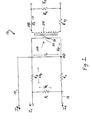
- a dual-rated current transformer circuit 10 is illustrated in Fig. 1 .
- Circuit 10 includes resistors R 1 , R 2 and R 3 connected in series.
- a first current I A or a second, different current I B is fed via current lines 12 and 14.
- a common current I C represents a common return path for both I A and I B .
- a current transformer 20 communicates with both currents I A and I B .
- Transformer 20 is a dual-rated transformer as both of the different currents rates I A or I B will produce the same current within the primary coil of the transformer, which will be described further herein.
- transformer 20 generates a current I P proportional to either current I A or I B .
- Transformer 20 includes a primary coil 22 and a secondary coil 24.
- transformer 20 can be a ferromagnetic core transformer.
- Primary coil 22 is single turn while the secondary coil 24 has multiple turns, for example, 13,000 turns.
- the stepped-down current I S of secondary coil 24 is proportional to the current I P through primary coil 22, said current I P being the same for both current rates I A or I B .
- the circuit of the present invention is designed for both I A or I B such that a standard transformer could be used for the most common relay input currents.
- Secondary coil 24 is designed to provide a low reflected resistance to primary 22 and a low burden to the transformer.
- Secondary coil 24 includes resistance R TS .
- a fourth resistor R 4 together with R TS , reflects to the primary.
- the polarity of primary coil 22 is noted at 26 and the polarity of secondary coil 24 at 28.
- An output burden which is low minimizes the transformer size.
- the output burden should be lower than the transformer secondary resistance R TS .
- the resistor network R 1 , R 2 and R 3 provides for two different current inputs I A or I B to supply a current to transformer primary 22 at a value lower than I B .
- current I B is delivered along line 14 to node 30, and because of the shunt arrangement of the circuit, results in the current I P through the transformer primary.
- Current I A travels to node 30 via line 12 and also produces the same current I P .
- V O I P N P R 4 / N S
- V P V S x N P / N S
- R P Letting R P be the value of the secondary resistance reflected to the primary:
- I A or I B are current sources which come from a current transformer of the power system which typically has a source impedance greater than 100 ⁇ , they typically would have an impedance more than two orders of magnitude higher than the sum of R 1 + R 2 + R 3 .
- V P I P ⁇ R TS + R 4 / N S 2
- I PC is approximately 1 % of I P and can be corrected by lowering the secondary turns.
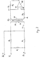
- transformer 20 includes a first primary coil 22 through which current I AP flows and a second primary coil 34 through which current I BP flows. If R 3 ( Fig. 1 ) becomes zero, I B will equal the current through the primary I P , see equation (3). Because the connection from I B to I C will have some resistance, the current should flow through second primary 34. The end of the second primary for I BP is connected to I C at the same node 36 as R 1 to prevent current flowing through R 1 in series with R 2 The current I B which is equal to I BP flows through primary coil 34 and back to I C .
- FIG. 3 another embodiment of the invention is shown, wherein the voltage burden of transformer 20 is reduced by approximately the value of R 4 by the addition of an inverting amplifier 40.
- Amplifier 40 includes an inverting input terminal 42 marked (-), noninverting input terminal 44 marked (+) and an output terminal 46.
- the circuit also includes secondary coil 24 having a polarity shown at 32.
- the transformer output does not see the burden of R 4 which would allow for a higher input current rating. Because the burden is reduced, the transformer size can be reduced with the same input current rating.
- the transformer 20 includes a bobbin 50 which has three flanges, 52 54 and 56.
- the bobbin has a first winding area 58 between flanges 54 and 56 and a second winding area 60 substantially larger than area 58 between flanges 52 and 54.
- the primary coil 22 is wrapped by at least one turn around the bobbin in area 58 and the secondary coil 24 is wrapped around the larger area 60.
- the majority of the winding in transformer 20 is the secondary winding which will produce a low resistance. This reduces the flux excursion and current excitation of the magnetic material 62 which is wrapped about the bobbin.
- Magnetic material 62 is a low excitation material. Using most of the winding area for the secondary winding and using a low excitation material for the magnetics are two design techniques which enable the size of the transformer to be reduced.
- the dual-rated current transformer circuit of the present invention allows for two different current input ratings to be delivered to the transformer. Moreover, the circuit can be miniaturized due to the input circuit which lowers the input current to the transformer and design techniques of the transformer which allow for size reduction.
Landscapes
- Power Engineering (AREA)
- Engineering & Computer Science (AREA)
- Transformers For Measuring Instruments (AREA)
- Amplifiers (AREA)
- Control Of Electrical Variables (AREA)
- Interface Circuits In Exchanges (AREA)
- Breakers (AREA)
- Measuring Instrument Details And Bridges, And Automatic Balancing Devices (AREA)
- Transmission And Conversion Of Sensor Element Output (AREA)
- Arrangements For Transmission Of Measured Signals (AREA)
- Measurement Of Current Or Voltage (AREA)
- Coils Or Transformers For Communication (AREA)
- Discharge Heating (AREA)
- Emergency Protection Circuit Devices (AREA)
Claims (11)
- Stromwandlerschaltung (10) für zwei Nennströme, aufweisend:einen Transformator (20) mit einer Eingangsleitung;einen ersten Schaltkreis in Verbindung mit der Eingangsleitung, wobei der erste Schaltkreis dafür eingerichtet ist, einen ersten Strom (IA) aufzunehmen; undeinen zweiten Schaltkreis in Verbindung mit der Eingangsleitung, wobei der zweite Schaltkreis dafür eingerichtet ist, einen zweiten Strom (IB) aufzunehmen, der sich von dem ersten Strom (IA) unterscheidet, wobei der erste Schaltkreis und der zweite Schaltkreis jeweils dafür eingerichtet sind, einen dritten Strom (IP) an die Eingangsleitung zu liefern, der derselbe unabhängig davon ist, ob der erste Schaltkreis oder der zweite Schaltkreis den dritten Strom liefert.
- Schaltung nach Anspruch 1, wobei sich der erste Schaltkreis und der zweite Schaltkreis eine gemeinsame Stromrückleitung teilen.
- Schaltung nach Anspruch 1, wobei wenigstens einer von dem ersten Schaltkreis und dem zweiten Schaltkreis mehrere Widerstände aufweist.
- Schaltung nach Anspruch 1, wobei der Transformator (20) einen heruntergestuften Strom auf einer Ausgangsleitung liefert.
- Schaltung nach Anspruch 1, wobei der Transformator (20) eine Primärspule (22) und eine Sekundärspule (24) besitzt, wobei die Sekundärspule eine niedrige reflektierte Impedanz an die Primärspule liefert.
- Schaltung nach Anspruch 1, wobei der Transformator (20) um eine Primärspule (22) und eine Sekundärspule (24) gewickeltes magnetisches Material aufweist.
- Schaltung nach Anspruch 6, wobei das magnetische Material ein Material des Typs mit geringer Erregungsenergie ist.
- Schaltung nach Anspruch 1, wobei der Transformator (20) eine Primärspule (22) und eine Sekundärspule (24) besitzt, wobei die Sekundärspule einen niedrigen Widerstand an die Primärspule und eine niedrige Last an den Transformator reflektiert.
- Schaltung nach Anspruch 1, wobei der Transformator (20) mehrere Primärspulen aufweist.
- Schaltung nach Anspruch 9, wobei jede von den mehreren Primärspulen nur eine Windung aufweist.
- Schaltung nach Anspruch 1, welcher ferner einen mit dem Transformator verbundenen Operationsverstärker (40) aufweist.
Applications Claiming Priority (3)
| Application Number | Priority Date | Filing Date | Title |
|---|---|---|---|
| US343456 | 1999-06-30 | ||
| US09/343,456 US6198268B1 (en) | 1999-06-30 | 1999-06-30 | Dual-rated current transformer circuit having at least two input circuits |
| PCT/US2000/017809 WO2001001426A1 (en) | 1999-06-30 | 2000-06-29 | Dual-rated current transformer circuit |
Publications (3)
| Publication Number | Publication Date |
|---|---|
| EP1108260A1 EP1108260A1 (de) | 2001-06-20 |
| EP1108260A4 EP1108260A4 (de) | 2009-03-25 |
| EP1108260B1 true EP1108260B1 (de) | 2011-11-02 |
Family
ID=23346199
Family Applications (1)
| Application Number | Title | Priority Date | Filing Date |
|---|---|---|---|
| EP00946885A Expired - Lifetime EP1108260B1 (de) | 1999-06-30 | 2000-06-29 | Strommundlerschaltung mit zweistufigem strom |
Country Status (14)
| Country | Link |
|---|---|
| US (1) | US6198268B1 (de) |
| EP (1) | EP1108260B1 (de) |
| JP (1) | JP4846149B2 (de) |
| KR (1) | KR100737061B1 (de) |
| CN (1) | CN1191595C (de) |
| AT (1) | ATE532192T1 (de) |
| AU (1) | AU758432B2 (de) |
| BR (1) | BRPI0006851B1 (de) |
| CA (1) | CA2340775C (de) |
| HU (1) | HU229697B1 (de) |
| NO (1) | NO321747B1 (de) |
| PL (1) | PL194110B1 (de) |
| WO (1) | WO2001001426A1 (de) |
| ZA (1) | ZA200101420B (de) |
Families Citing this family (2)
| Publication number | Priority date | Publication date | Assignee | Title |
|---|---|---|---|---|
| CN100583322C (zh) * | 2006-10-16 | 2010-01-20 | 台达电子工业股份有限公司 | 整合式电流感测变压器及使用该变压器的电流感测电路 |
| CN105067861A (zh) * | 2015-08-22 | 2015-11-18 | 安徽千恩智能科技股份有限公司 | 分流式电流取样互感器 |
Citations (1)
| Publication number | Priority date | Publication date | Assignee | Title |
|---|---|---|---|---|
| US5150039A (en) * | 1988-06-17 | 1992-09-22 | Avocat Jean Paul P | Electrical measuring transformer |
Family Cites Families (15)
| Publication number | Priority date | Publication date | Assignee | Title |
|---|---|---|---|---|
| GB372404A (en) * | 1931-02-09 | 1932-05-09 | British Thomson Houston Co Ltd | Improvements in electrical measuring or relay apparatus, particularly for high potential circuits |
| US2096801A (en) * | 1937-01-14 | 1937-10-26 | Bell Telephone Labor Inc | Power transformer |
| US4140961A (en) * | 1977-06-21 | 1979-02-20 | Mitsubishi Denki Kabushiki Kaisha | Shunt circuit for an insulation type current transformer to adapt to a wide-band of frequency |
| DE2833203A1 (de) * | 1978-07-27 | 1980-02-07 | Siemens Ag | Messwandler mit einer von einem zu messenden strom durchflossenen primaerwicklung |
| US4301491A (en) | 1980-01-21 | 1981-11-17 | Gould Inc. | Combined fault current and applied voltage tripping for solid state trip circuit and particular current transformer construction |
| CA1211169A (fr) * | 1984-04-03 | 1986-09-09 | Nicolai Alexandrov | Transformateur de distribution a circuit magnetique enroule |
| US5061896A (en) * | 1985-09-03 | 1991-10-29 | United Technologies Corporation | Variable transformer to detect linear displacement with constant output amplitude |
| JPH0282020U (de) * | 1988-12-15 | 1990-06-25 | ||
| JPH067536B2 (ja) * | 1990-05-31 | 1994-01-26 | 株式会社高岳製作所 | ワイドレンジ変流器 |
| US5015983A (en) | 1990-06-18 | 1991-05-14 | General Electric Company | Compact circuit interrupter having multiple ampere ratings |
| US5214407A (en) * | 1991-11-06 | 1993-05-25 | Hewlett-Packard Company | High performance current shunt |
| JP2690647B2 (ja) * | 1991-11-08 | 1997-12-10 | 三菱電機株式会社 | 誤差補償型変圧器 |
| US5214470A (en) * | 1992-04-09 | 1993-05-25 | Xerox Corporation | Method and apparatus for compensating for dirt or etched areas on a document platen |
| JPH06174754A (ja) * | 1992-12-03 | 1994-06-24 | Mitsubishi Electric Corp | ワイドレンジ電流センサ |
| JPH06242147A (ja) * | 1993-02-19 | 1994-09-02 | Mitsubishi Electric Corp | 変流装置 |
-
1999
- 1999-06-30 US US09/343,456 patent/US6198268B1/en not_active Expired - Lifetime
-
2000
- 2000-06-29 HU HU0103335A patent/HU229697B1/hu not_active IP Right Cessation
- 2000-06-29 BR BRPI0006851A patent/BRPI0006851B1/pt not_active IP Right Cessation
- 2000-06-29 AT AT00946885T patent/ATE532192T1/de active
- 2000-06-29 WO PCT/US2000/017809 patent/WO2001001426A1/en not_active Ceased
- 2000-06-29 CN CNB008012792A patent/CN1191595C/zh not_active Expired - Fee Related
- 2000-06-29 KR KR1020017002484A patent/KR100737061B1/ko not_active Expired - Fee Related
- 2000-06-29 JP JP2001506560A patent/JP4846149B2/ja not_active Expired - Fee Related
- 2000-06-29 AU AU60575/00A patent/AU758432B2/en not_active Ceased
- 2000-06-29 CA CA002340775A patent/CA2340775C/en not_active Expired - Fee Related
- 2000-06-29 EP EP00946885A patent/EP1108260B1/de not_active Expired - Lifetime
- 2000-06-29 PL PL00346266A patent/PL194110B1/pl unknown
-
2001
- 2001-02-20 ZA ZA200101420A patent/ZA200101420B/en unknown
- 2001-02-27 NO NO20010993A patent/NO321747B1/no not_active IP Right Cessation
Patent Citations (1)
| Publication number | Priority date | Publication date | Assignee | Title |
|---|---|---|---|---|
| US5150039A (en) * | 1988-06-17 | 1992-09-22 | Avocat Jean Paul P | Electrical measuring transformer |
Also Published As
| Publication number | Publication date |
|---|---|
| CA2340775C (en) | 2008-09-30 |
| CN1191595C (zh) | 2005-03-02 |
| HUP0103335A3 (en) | 2004-01-28 |
| JP2003503836A (ja) | 2003-01-28 |
| BRPI0006851B1 (pt) | 2016-01-26 |
| EP1108260A4 (de) | 2009-03-25 |
| HU229697B1 (en) | 2014-05-28 |
| ZA200101420B (en) | 2002-05-20 |
| NO321747B1 (no) | 2006-06-26 |
| NO20010993L (no) | 2001-02-27 |
| US6198268B1 (en) | 2001-03-06 |
| AU6057500A (en) | 2001-01-31 |
| KR20030044740A (ko) | 2003-06-09 |
| NO20010993D0 (no) | 2001-02-27 |
| JP4846149B2 (ja) | 2011-12-28 |
| WO2001001426A1 (en) | 2001-01-04 |
| ATE532192T1 (de) | 2011-11-15 |
| HUP0103335A2 (hu) | 2001-12-28 |
| EP1108260A1 (de) | 2001-06-20 |
| PL194110B1 (pl) | 2007-04-30 |
| AU758432B2 (en) | 2003-03-20 |
| BR0006851A (pt) | 2001-07-03 |
| KR100737061B1 (ko) | 2007-07-06 |
| CN1316090A (zh) | 2001-10-03 |
| CA2340775A1 (en) | 2001-01-04 |
| PL346266A1 (en) | 2002-01-28 |
Similar Documents
| Publication | Publication Date | Title |
|---|---|---|
| US6417661B1 (en) | Self powered current sensor | |
| US5331500A (en) | Circuit breaker comprising a card interfacing with a trip device | |
| US5583732A (en) | Modular current transformer for electronic circuit interrupters | |
| US6181125B1 (en) | Combination apparatus of a distribution transformer and switches | |
| US4295175A (en) | Pilot wire relay protection system for electrical distribution networks | |
| CA1060087A (en) | Two pole ground fault circuit interrupter with improved rectified supply and transient suppression for a trip circuit | |
| EP0300075B1 (de) | Stromdetektor | |
| US6198268B1 (en) | Dual-rated current transformer circuit having at least two input circuits | |
| US5774320A (en) | Modular current transformer for electronic circuit interrupters | |
| JP3221128B2 (ja) | 電流検出装置 | |
| US6111489A (en) | Circuit breaker configuration | |
| JPH10201097A (ja) | 単相3線式低圧配電システム | |
| US5329414A (en) | Protective relay interface | |
| JP3446268B2 (ja) | 変圧器の保護装置 | |
| JP4137912B2 (ja) | 電力供給方法及び電力供給システム | |
| US2341954A (en) | Current transformer | |
| JPH0154927B2 (de) | ||
| JPH05205950A (ja) | 単相負荷時タップ切換変圧器 | |
| RU1798824C (ru) | Трехфазный реактор нулевой последовательности | |
| US4319183A (en) | Control windings for self-saturating electrical reactors | |
| JPH0263281B2 (de) | ||
| Burnett | IDMTL relay tripping of main incoming circuit breakers | |
| Zocholl | New Applications Requiring Solid State Protective Relay Characteristics | |
| JPS5843890B2 (ja) | 親子形計器用変圧器 | |
| JPH0247174B2 (de) |
Legal Events
| Date | Code | Title | Description |
|---|---|---|---|
| PUAI | Public reference made under article 153(3) epc to a published international application that has entered the european phase |
Free format text: ORIGINAL CODE: 0009012 |
|
| AK | Designated contracting states |
Kind code of ref document: A1 Designated state(s): AT BE CH CY DE DK ES FI FR GB GR IE IT LI LU MC NL PT SE |
|
| AX | Request for extension of the european patent |
Free format text: AL;LT;LV;MK;RO;SI |
|
| 17P | Request for examination filed |
Effective date: 20010704 |
|
| A4 | Supplementary search report drawn up and despatched |
Effective date: 20090224 |
|
| RIC1 | Information provided on ipc code assigned before grant |
Ipc: H01F 27/42 20060101ALN20090218BHEP Ipc: H01F 38/00 20060101AFI20010109BHEP Ipc: H01F 27/38 20060101ALN20090218BHEP Ipc: G01R 15/18 20060101ALN20090218BHEP Ipc: G01R 15/14 20060101ALI20090218BHEP Ipc: G01R 1/20 20060101ALI20090218BHEP |
|
| 17Q | First examination report despatched |
Effective date: 20090624 |
|
| GRAP | Despatch of communication of intention to grant a patent |
Free format text: ORIGINAL CODE: EPIDOSNIGR1 |
|
| GRAS | Grant fee paid |
Free format text: ORIGINAL CODE: EPIDOSNIGR3 |
|
| GRAA | (expected) grant |
Free format text: ORIGINAL CODE: 0009210 |
|
| AK | Designated contracting states |
Kind code of ref document: B1 Designated state(s): AT BE CH CY DE DK ES FI FR GB GR IE IT LI LU MC NL PT SE |
|
| REG | Reference to a national code |
Ref country code: GB Ref legal event code: FG4D |
|
| REG | Reference to a national code |
Ref country code: CH Ref legal event code: EP |
|
| REG | Reference to a national code |
Ref country code: IE Ref legal event code: FG4D |
|
| REG | Reference to a national code |
Ref country code: DE Ref legal event code: R096 Ref document number: 60046630 Country of ref document: DE Effective date: 20120119 |
|
| REG | Reference to a national code |
Ref country code: NL Ref legal event code: VDEP Effective date: 20111102 |
|
| PG25 | Lapsed in a contracting state [announced via postgrant information from national office to epo] |
Ref country code: PT Free format text: LAPSE BECAUSE OF FAILURE TO SUBMIT A TRANSLATION OF THE DESCRIPTION OR TO PAY THE FEE WITHIN THE PRESCRIBED TIME-LIMIT Effective date: 20120302 Ref country code: GR Free format text: LAPSE BECAUSE OF FAILURE TO SUBMIT A TRANSLATION OF THE DESCRIPTION OR TO PAY THE FEE WITHIN THE PRESCRIBED TIME-LIMIT Effective date: 20120203 Ref country code: NL Free format text: LAPSE BECAUSE OF FAILURE TO SUBMIT A TRANSLATION OF THE DESCRIPTION OR TO PAY THE FEE WITHIN THE PRESCRIBED TIME-LIMIT Effective date: 20111102 Ref country code: SE Free format text: LAPSE BECAUSE OF FAILURE TO SUBMIT A TRANSLATION OF THE DESCRIPTION OR TO PAY THE FEE WITHIN THE PRESCRIBED TIME-LIMIT Effective date: 20111102 Ref country code: BE Free format text: LAPSE BECAUSE OF FAILURE TO SUBMIT A TRANSLATION OF THE DESCRIPTION OR TO PAY THE FEE WITHIN THE PRESCRIBED TIME-LIMIT Effective date: 20111102 |
|
| PG25 | Lapsed in a contracting state [announced via postgrant information from national office to epo] |
Ref country code: CY Free format text: LAPSE BECAUSE OF FAILURE TO SUBMIT A TRANSLATION OF THE DESCRIPTION OR TO PAY THE FEE WITHIN THE PRESCRIBED TIME-LIMIT Effective date: 20111102 |
|
| PG25 | Lapsed in a contracting state [announced via postgrant information from national office to epo] |
Ref country code: DK Free format text: LAPSE BECAUSE OF FAILURE TO SUBMIT A TRANSLATION OF THE DESCRIPTION OR TO PAY THE FEE WITHIN THE PRESCRIBED TIME-LIMIT Effective date: 20111102 |
|
| PG25 | Lapsed in a contracting state [announced via postgrant information from national office to epo] |
Ref country code: IT Free format text: LAPSE BECAUSE OF FAILURE TO SUBMIT A TRANSLATION OF THE DESCRIPTION OR TO PAY THE FEE WITHIN THE PRESCRIBED TIME-LIMIT Effective date: 20111102 |
|
| PLBE | No opposition filed within time limit |
Free format text: ORIGINAL CODE: 0009261 |
|
| STAA | Information on the status of an ep patent application or granted ep patent |
Free format text: STATUS: NO OPPOSITION FILED WITHIN TIME LIMIT |
|
| REG | Reference to a national code |
Ref country code: AT Ref legal event code: MK05 Ref document number: 532192 Country of ref document: AT Kind code of ref document: T Effective date: 20111102 |
|
| 26N | No opposition filed |
Effective date: 20120803 |
|
| REG | Reference to a national code |
Ref country code: DE Ref legal event code: R097 Ref document number: 60046630 Country of ref document: DE Effective date: 20120803 |
|
| PG25 | Lapsed in a contracting state [announced via postgrant information from national office to epo] |
Ref country code: MC Free format text: LAPSE BECAUSE OF NON-PAYMENT OF DUE FEES Effective date: 20120630 Ref country code: AT Free format text: LAPSE BECAUSE OF FAILURE TO SUBMIT A TRANSLATION OF THE DESCRIPTION OR TO PAY THE FEE WITHIN THE PRESCRIBED TIME-LIMIT Effective date: 20111102 |
|
| REG | Reference to a national code |
Ref country code: CH Ref legal event code: PL |
|
| REG | Reference to a national code |
Ref country code: CH Ref legal event code: PL |
|
| PG25 | Lapsed in a contracting state [announced via postgrant information from national office to epo] |
Ref country code: ES Free format text: LAPSE BECAUSE OF FAILURE TO SUBMIT A TRANSLATION OF THE DESCRIPTION OR TO PAY THE FEE WITHIN THE PRESCRIBED TIME-LIMIT Effective date: 20120213 Ref country code: CH Free format text: LAPSE BECAUSE OF NON-PAYMENT OF DUE FEES Effective date: 20120630 Ref country code: LI Free format text: LAPSE BECAUSE OF NON-PAYMENT OF DUE FEES Effective date: 20120630 |
|
| PG25 | Lapsed in a contracting state [announced via postgrant information from national office to epo] |
Ref country code: FI Free format text: LAPSE BECAUSE OF FAILURE TO SUBMIT A TRANSLATION OF THE DESCRIPTION OR TO PAY THE FEE WITHIN THE PRESCRIBED TIME-LIMIT Effective date: 20111102 |
|
| PG25 | Lapsed in a contracting state [announced via postgrant information from national office to epo] |
Ref country code: LU Free format text: LAPSE BECAUSE OF NON-PAYMENT OF DUE FEES Effective date: 20120629 |
|
| PGFP | Annual fee paid to national office [announced via postgrant information from national office to epo] |
Ref country code: IE Payment date: 20150630 Year of fee payment: 16 |
|
| REG | Reference to a national code |
Ref country code: FR Ref legal event code: PLFP Year of fee payment: 17 |
|
| PGFP | Annual fee paid to national office [announced via postgrant information from national office to epo] |
Ref country code: GB Payment date: 20160627 Year of fee payment: 17 |
|
| PGFP | Annual fee paid to national office [announced via postgrant information from national office to epo] |
Ref country code: FR Payment date: 20160628 Year of fee payment: 17 |
|
| PGFP | Annual fee paid to national office [announced via postgrant information from national office to epo] |
Ref country code: DE Payment date: 20160628 Year of fee payment: 17 |
|
| REG | Reference to a national code |
Ref country code: IE Ref legal event code: MM4A |
|
| PG25 | Lapsed in a contracting state [announced via postgrant information from national office to epo] |
Ref country code: IE Free format text: LAPSE BECAUSE OF NON-PAYMENT OF DUE FEES Effective date: 20160629 |
|
| REG | Reference to a national code |
Ref country code: DE Ref legal event code: R119 Ref document number: 60046630 Country of ref document: DE |
|
| GBPC | Gb: european patent ceased through non-payment of renewal fee |
Effective date: 20170629 |
|
| REG | Reference to a national code |
Ref country code: FR Ref legal event code: ST Effective date: 20180228 |
|
| PG25 | Lapsed in a contracting state [announced via postgrant information from national office to epo] |
Ref country code: DE Free format text: LAPSE BECAUSE OF NON-PAYMENT OF DUE FEES Effective date: 20180103 Ref country code: GB Free format text: LAPSE BECAUSE OF NON-PAYMENT OF DUE FEES Effective date: 20170629 |
|
| PG25 | Lapsed in a contracting state [announced via postgrant information from national office to epo] |
Ref country code: FR Free format text: LAPSE BECAUSE OF NON-PAYMENT OF DUE FEES Effective date: 20170630 |