EP1108689A2 - Verfahren zur thermischen Behandlung eines Überfangrohres aus Quarzglas - Google Patents
Verfahren zur thermischen Behandlung eines Überfangrohres aus Quarzglas Download PDFInfo
- Publication number
- EP1108689A2 EP1108689A2 EP00310756A EP00310756A EP1108689A2 EP 1108689 A2 EP1108689 A2 EP 1108689A2 EP 00310756 A EP00310756 A EP 00310756A EP 00310756 A EP00310756 A EP 00310756A EP 1108689 A2 EP1108689 A2 EP 1108689A2
- Authority
- EP
- European Patent Office
- Prior art keywords
- tube
- handle
- tip
- silica
- hole
- Prior art date
- Legal status (The legal status is an assumption and is not a legal conclusion. Google has not performed a legal analysis and makes no representation as to the accuracy of the status listed.)
- Withdrawn
Links
Images

Classifications
-
- C—CHEMISTRY; METALLURGY
- C03—GLASS; MINERAL OR SLAG WOOL
- C03B—MANUFACTURE, SHAPING, OR SUPPLEMENTARY PROCESSES
- C03B37/00—Manufacture or treatment of flakes, fibres, or filaments from softened glass, minerals, or slags
- C03B37/075—Manufacture of non-optical fibres or filaments consisting of different sorts of glass or characterised by shape, e.g. undulated fibres
-
- C—CHEMISTRY; METALLURGY
- C03—GLASS; MINERAL OR SLAG WOOL
- C03B—MANUFACTURE, SHAPING, OR SUPPLEMENTARY PROCESSES
- C03B37/00—Manufacture or treatment of flakes, fibres, or filaments from softened glass, minerals, or slags
- C03B37/01—Manufacture of glass fibres or filaments
- C03B37/012—Manufacture of preforms for drawing fibres or filaments
- C03B37/014—Manufacture of preforms for drawing fibres or filaments made entirely or partially by chemical means, e.g. vapour phase deposition of bulk porous glass either by outside vapour deposition [OVD], or by outside vapour phase oxidation [OVPO] or by vapour axial deposition [VAD]
- C03B37/01446—Thermal after-treatment of preforms, e.g. dehydrating, consolidating, sintering
- C03B37/0146—Furnaces therefor, e.g. muffle tubes, furnace linings
-
- C—CHEMISTRY; METALLURGY
- C03—GLASS; MINERAL OR SLAG WOOL
- C03B—MANUFACTURE, SHAPING, OR SUPPLEMENTARY PROCESSES
- C03B19/00—Other methods of shaping glass
- C03B19/12—Other methods of shaping glass by liquid-phase reaction processes
-
- C—CHEMISTRY; METALLURGY
- C03—GLASS; MINERAL OR SLAG WOOL
- C03B—MANUFACTURE, SHAPING, OR SUPPLEMENTARY PROCESSES
- C03B37/00—Manufacture or treatment of flakes, fibres, or filaments from softened glass, minerals, or slags
- C03B37/01—Manufacture of glass fibres or filaments
- C03B37/012—Manufacture of preforms for drawing fibres or filaments
- C03B37/01205—Manufacture of preforms for drawing fibres or filaments starting from tubes, rods, fibres or filaments
-
- C—CHEMISTRY; METALLURGY
- C03—GLASS; MINERAL OR SLAG WOOL
- C03B—MANUFACTURE, SHAPING, OR SUPPLEMENTARY PROCESSES
- C03B37/00—Manufacture or treatment of flakes, fibres, or filaments from softened glass, minerals, or slags
- C03B37/01—Manufacture of glass fibres or filaments
- C03B37/012—Manufacture of preforms for drawing fibres or filaments
- C03B37/014—Manufacture of preforms for drawing fibres or filaments made entirely or partially by chemical means, e.g. vapour phase deposition of bulk porous glass either by outside vapour deposition [OVD], or by outside vapour phase oxidation [OVPO] or by vapour axial deposition [VAD]
- C03B37/01486—Means for supporting, rotating or translating the preforms being formed, e.g. lathes
-
- Y—GENERAL TAGGING OF NEW TECHNOLOGICAL DEVELOPMENTS; GENERAL TAGGING OF CROSS-SECTIONAL TECHNOLOGIES SPANNING OVER SEVERAL SECTIONS OF THE IPC; TECHNICAL SUBJECTS COVERED BY FORMER USPC CROSS-REFERENCE ART COLLECTIONS [XRACs] AND DIGESTS
- Y02—TECHNOLOGIES OR APPLICATIONS FOR MITIGATION OR ADAPTATION AGAINST CLIMATE CHANGE
- Y02P—CLIMATE CHANGE MITIGATION TECHNOLOGIES IN THE PRODUCTION OR PROCESSING OF GOODS
- Y02P40/00—Technologies relating to the processing of minerals
- Y02P40/50—Glass production, e.g. reusing waste heat during processing or shaping
- Y02P40/57—Improving the yield, e-g- reduction of reject rates
Definitions
- the invention relates to fabrication of silica optical fiber, in particular fabrication of fiber preforms by a rod-in-tube technique.
- Optical fiber is produced from a glass preform.
- the preform is generally arranged vertically in a draw tower such that a portion of the preform is lowered into a furnace region.
- the portion of the preform placed into the furnace region begins to soften, and the lower end of the preform forms what is known as the neck-down region, where glass flows from the original cross-sectional area of the preform to the desired cross-sectional area of the fiber. From the lower tip of this neck-down region, the optical fiber is drawn.
- Optical transmission fiber typically contains a high-purity silica glass core optionally doped with a refractive index-raising element such as germanium, an inner cladding of high-purity silica glass optionally doped with a refractive index-lowering element such as fluorine, and an outer cladding of undoped silica glass.
- the preforms for making such fiber are fabricated by forming an overcladding tube for the outer cladding, and separately forming a rod containing the core material and inner cladding material.
- the core/inner cladding are fabricated by any of a variety of vapor deposition methods known to those skilled in the art, including vapor axial deposition (VAD), outside vapor deposition (OVD), and modified chemical vapor deposition (MCVD).
- VAD vapor axial deposition
- OLED outside vapor deposition
- MCVD modified chemical vapor deposition
- VAD vapor axial deposition
- OLED outside vapor deposition
- MCVD modified chemical vapor deposition
- MCVD is discussed in U.S. Patent Nos. 4,217,027; 4,262,035; and 4,909,816, the disclosures of which are hereby incorporated by reference.
- MCVD involves passing a high-purity gas, e.g., a mixture of gases containing silicon and germanium, through the interior of a silica tube (known as the substrate tube) while heating the outside of the tube with a traversing oxy-hydrogen torch.
- a high-purity gas e.g
- a gas phase reaction occurs that deposits particles on the tube wall. This deposit, which forms ahead of the torch, is sintered as the torch passes over it. The process is repeated in successive passes until the requisite quantity of silica and/or germanium-doped silica is deposited.
- the body is heated to collapse the substrate tube and obtain a consolidated core rod in which the substrate tube constitutes the outer portion of the inner cladding material.
- the overcladding tube is typically placed over the core rod, and the components are heated and collapsed into a solid, consolidated preform, as discussed in U.S. Patent No. 4,775,401, the disclosure of which is hereby incorporated by reference.
- Forming a fiber preform using such a process therefore requires both a substrate tube and an overcladding tube.
- both types of tubes were formed from fused quartz or by soot methods, i.e., depositing glass on a mandrel by directing at the mandrel glass particles formed by flame hydrolysis of silicon tetrachloride. Both methods were energy intensive and costly, however, and alternatives were sought.
- the overcladding glass does not have to meet the optical performance specifications to which the core and the inner cladding must conform (but still must be substantially free of flaw-inducing refractory oxide particles) . For this reason, efforts to both ease and speed manufacture of fiber preforms focused on methods of making overcladding tubes. One area of such efforts is the use of a sol-gel casting process.
- U.S. Patent No. 5,240,488 discloses a sol-gel casting process capable of producing crack-free overcladding preform tubes of a kilogram or larger.
- a colloidal silicon dispersion e.g., fumed silica
- the pH is raised to a value of about 11 to about 14 by use of a base, and the dispersion is then aged.
- a gelling agent such as methyl formate is added to the dispersion to lower the pH.
- the mixture is pumped into a tubular mold containing a central mandrel, and the gel is aged in the mold for 1 to 24 hours.
- the mandrel is removed, and the gelled body is then extracted from the mold, typically by launching the body from the mold in water to prevent breakage.
- the body is then dried, fired to remove volatile organic materials and water, and then sintered to form the finished overcladding tube.
- the core rod is then inserted into the tube, and the assembly is collapsed into a fiber preform.
- the invention involves fabricating a ceramic tube, e.g., a silica overcladding tube, with very little bow, e.g., as low as 0.3 mm per meter.
- the invention involves securing the tube by a handle that both allows the tube to hang plumb during treatment, and also is capable of deforming during such heat treatment to maintain the plumb arrangement.
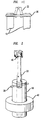
- a handle tip 22 is inserted into the bore of the tube 10 such that holes 12, 24 in the tube and the tip are aligned, and a silica pin 30 is inserted.
- the tube is hung by securing the opposing end of the handle, and the tube/handle assembly is fired at a temperature suitable to remove any remaining impurities, generally by raising the assembly through the hot zone of a furnace.
- the furnace is generally heated to a sintering temperature, and the tube is pulled back up through the hot zone (an ascending sinter).
- the green silica tube tends to shrink to 3/4 of its original diameter during this sinter.
- the high temperature softens the silica and thereby induces some flexibility to the tube and the handle tip.
- the tube thus deforms around the tip, forming a continuous interface, with the tip deforming as well.
- the handle tip tends to deform in the plumb arrangement, as opposed to the tube being forced to bow to remain plumb, and this deformation of the tip substantially reduces inducement of bow in the tube.
- Figs. 1A- 1D illustrate the configuration of ceramic tube and handle tip useful in the invention.
- the invention involves fabricating a ceramic tube, e.g., a silica overcladding tube, with very little bow, e.g., typically less than 0.3 mm per meter, optionally as low as 0.1 mm per meter.
- a sol-gel process such as discussed in U.S. Patent No. 5,240,488, the process of the invention is as follows.
- a sol-gel silica tube is launched and dried as discussed above.
- the tube is then heated, e.g., to around 900 to 1000°C, to burn out some organics as well as water (often referred to as a dehydroxylation step).
- the tube is in green form, i.e., the tube is not sintered to glass, but is stronger than a gel body. In this green form, the tube is capable of being machined.
- a hole 12 is formed, typically by drilling, through the entire diameter of the tube 10 in a direction perpendicular to the tube axis.
- the hole 12 is proximate to one end of the tube, and is typically located a distance from the tube end at least equal to the tube wall thickness.
- the hole 12 should be through the true diameter of the tube 10.
- the singular term "hole” is used, although there are essentially two holes - through opposing walls of the tube. As used herein, hole indicates either a single hole through a solid body, or aligned holes through opposing walls of a tubular body.
- a handle 20 having a tip 22 is provided, as shown in Fig. 1B.
- the handle tip 22 is typically tubular, and, in this embodiment, is formed from silica.
- the tube wall should be of sufficient thickness to avoid excessive stretching during the subsequent processing steps, e.g., thickness ranging from 4 mm to 8 mm for 15 kg green tube bodies.
- the tip 22 has a hole 24 formed therein that corresponds to the hole 12 in the overcladding tube 10.
- the tip 22 typically contains venting holes 26, which allow undesirable gases, e.g., water vapor, to escape during sintering (see below).
- the outer diameter of the tip 22 is generally close to the inner diameter of the overcladding tube 10, e.g., about 1 mm less. This close fit allows for relatively precise centering of the tip 22 into the tube 10, as discussed below.
- the tip 22 is inserted into the bore of the tube 10 such that the holes 12, 24 are aligned, and a silica pin 30 is inserted.
- the close fit of the tip 22 outer diameter to the inner diameter of the tube 10 provides for relatively low misalignment to one side or the other, which is useful in attaining only a very small bow, as discussed below.
- the pin should be at least 10% longer than the outer diameter of the overcladding tube 10. Generally a pin diameter of about 6 mm is sufficient for overcladding tubes having (in green form) an outer diameter of 120 mm and a length of 1600 mm.
- the holes formed for the pin 30 should be just slightly larger than the pin diameter.
- the tube is hung by securing the opposing end of the handle 20, which has some shape, e.g., a knob 40 or fitting suitable for a universal joint, that allows the tube 10 to hang plumb in a furnace 42.
- some shape e.g., a knob 40 or fitting suitable for a universal joint, that allows the tube 10 to hang plumb in a furnace 42.
- a variety of configurations are suitable for this opposing end of the handle, with the goal being freedom of the handle, and thus the tube, to hang plumb, or at least substantially plumb.
- the tube/handle assembly is typically fired at a temperature suitable to remove any remaining impurities, e.g., at temperature around 1000 to 1300°C. Generally this is performed by translating or traversing the assembly through the hot zone of a furnace. Vent holes provided in the handle tip, as mentioned above, are advantageous in that they allow gaseous impurities, including water, to flow out from the interior of the tube.
- the furnace is generally heated to a sintering temperature, e.g., around 1500°C, and the tube is pulled back up through the hot zone (an ascending sinter).
- a sintering temperature e.g., around 1500°C
- the green silica tube tends to shrink to 3/4 of its original diameter during this sinter.
- the high temperature softens the silica and thereby induces some flexibility to the tube and the handle tip.
- the tube deforms around the tip, forming a continuous interface between the tip and tube, with the tip deforming as well.
- the joining of tip and tube occurs while the tube is hanging plumb, and the handle tip thus tends to deform to maintain this plumb position, instead of the tube itself bowing to maintain plumb.
- the handle is fabricated such that the tip is able to be cut from the remainder of the handle assembly, and a new tip attached. In this way, the consumable items used in the process are reduced.
- a core rod into the tube with very low incidence of marring, scratching, or other defacing, i.e., the less the bow, the less the likelihood of hitting the sides of the tube during core rod insertion.
- a close match of the core rod outer diameter and the overcladding tube inner diameter contributes to more desirable properties of the resultant fiber.
- the process is relatively simple to perform, and the tip/tube assembly is physically robust, exhibiting low level of mechanical failure. Due to these characteristics, as well as the low consumables, the process is cost-effective.
- the sintered tube is formed, it is possible to form a fiber preform by placing a core rod into the tube, and collapsing the assembly. Fiber is then drawn according to conventional techniques.
- the process of the invention is also contemplated for use with tubes formed with other ceramic materials and for various applications where substantially no bow is desired or required, in accordance with the guidelines presented above.
- other physical embodiments of the handle, handle tip, and pin are possible.
- Other techniques for inserting the pin and forming the hole in the tube and/or tip are also possible.
Landscapes
- Chemical & Material Sciences (AREA)
- Engineering & Computer Science (AREA)
- Organic Chemistry (AREA)
- Manufacturing & Machinery (AREA)
- Materials Engineering (AREA)
- Life Sciences & Earth Sciences (AREA)
- General Life Sciences & Earth Sciences (AREA)
- Geochemistry & Mineralogy (AREA)
- Chemical Kinetics & Catalysis (AREA)
- General Chemical & Material Sciences (AREA)
- Physics & Mathematics (AREA)
- Thermal Sciences (AREA)
- Manufacture, Treatment Of Glass Fibers (AREA)
Applications Claiming Priority (2)
| Application Number | Priority Date | Filing Date | Title |
|---|---|---|---|
| US459775 | 1999-12-13 | ||
| US09/459,775 US6550280B1 (en) | 1999-12-13 | 1999-12-13 | Process of sintering a hanging silica tube so as to exhibit a low bow |
Publications (2)
| Publication Number | Publication Date |
|---|---|
| EP1108689A2 true EP1108689A2 (de) | 2001-06-20 |
| EP1108689A3 EP1108689A3 (de) | 2002-06-19 |
Family
ID=23826104
Family Applications (1)
| Application Number | Title | Priority Date | Filing Date |
|---|---|---|---|
| EP00310756A Withdrawn EP1108689A3 (de) | 1999-12-13 | 2000-12-04 | Verfahren zur thermischen Behandlung eines Überfangrohres aus Quarzglas |
Country Status (6)
| Country | Link |
|---|---|
| US (1) | US6550280B1 (de) |
| EP (1) | EP1108689A3 (de) |
| JP (1) | JP2001192222A (de) |
| KR (1) | KR20010062341A (de) |
| AU (1) | AU7206100A (de) |
| CA (1) | CA2325327A1 (de) |
Cited By (1)
| Publication number | Priority date | Publication date | Assignee | Title |
|---|---|---|---|---|
| EP1110918A3 (de) * | 1999-12-22 | 2002-06-05 | Samsung Electronics Co., Ltd. | Vorrichtung und Verfahren zum Sintern eines Überfangrohres aus sol-gel-hergestelltem Glas für eine Vorform für optische Fasern |
Families Citing this family (5)
| Publication number | Priority date | Publication date | Assignee | Title |
|---|---|---|---|---|
| US6732549B1 (en) * | 2000-08-01 | 2004-05-11 | Lucent Technologies Inc. | Multi-pass sintering of a sol-gel body through a hot zone |
| US20040107735A1 (en) * | 2002-12-04 | 2004-06-10 | Fitel Usa Corp. | Rod-in-tube optical fiber preform and method |
| US20050097923A1 (en) * | 2003-11-12 | 2005-05-12 | General Electric Company | System and support rod assembly for sintering fiber optic sleeve tubes |
| JP5916551B2 (ja) * | 2011-09-30 | 2016-05-11 | 株式会社フジクラ | 光ファイバ用母材の製造方法、及び、光ファイバの製造方法 |
| CN104803596B (zh) * | 2015-05-13 | 2018-04-03 | 深圳特发信息光纤有限公司 | 一种光纤拉丝塔预制棒夹持装置 |
Family Cites Families (22)
| Publication number | Priority date | Publication date | Assignee | Title |
|---|---|---|---|---|
| US4909816A (en) | 1974-02-22 | 1990-03-20 | American Telephone And Telegraph Company, At&T Bell Laboratories | Optical fiber fabrication and resulting product |
| US4217027A (en) | 1974-02-22 | 1980-08-12 | Bell Telephone Laboratories, Incorporated | Optical fiber fabrication and resulting product |
| US4251251A (en) * | 1979-05-31 | 1981-02-17 | Corning Glass Works | Method of making optical devices |
| US4262035A (en) | 1980-03-07 | 1981-04-14 | Bell Telephone Laboratories, Incorporated | Modified chemical vapor deposition of an optical fiber using an rf plasma |
| JPS6221725A (ja) * | 1985-07-17 | 1987-01-30 | Furukawa Electric Co Ltd:The | 光フアイバ母材の製造方法 |
| US5378345A (en) * | 1986-07-25 | 1995-01-03 | Ceramatec, Inc. | Ceramic solid electrolyte-based electrochemical oxygen concentrator cell |
| US4775401A (en) | 1987-06-18 | 1988-10-04 | American Telephone And Telegraph Company, At&T Bell Laboratories | Method of producing an optical fiber |
| JPH02149442A (ja) * | 1988-12-01 | 1990-06-08 | Sumitomo Electric Ind Ltd | 光ファイバ用母材の製造方法 |
| JP2683757B2 (ja) * | 1988-12-15 | 1997-12-03 | 住友電気工業株式会社 | ガラス母材の支持方法及びその支持構造 |
| US5064588A (en) * | 1989-05-15 | 1991-11-12 | Ngk Insulators, Ltd. | Method of manufacturing elongate ceramic articles |
| US5151117A (en) * | 1991-06-14 | 1992-09-29 | Corning Incorporated | Solution doping of porous preforms |
| US5417399A (en) * | 1991-06-19 | 1995-05-23 | Sumitomo Electric Industries, Ltd. | Apparatus for supporting article in heating furnace |
| US5236481A (en) * | 1992-02-21 | 1993-08-17 | Corning Incorporated | Method of doping porous glass preforms |
| JP2879178B2 (ja) * | 1992-03-28 | 1999-04-05 | 日本碍子株式会社 | セラミックプッシュロッドおよびその製造方法 |
| CA2099942C (en) * | 1992-07-09 | 2004-10-26 | Sumio Hoshino | Method and apparatus for drawing glass preform for optical fiber |
| US5240488A (en) | 1992-08-14 | 1993-08-31 | At&T Bell Laboratories | Manufacture of vitreous silica product via a sol-gel process using a polymer additive |
| JPH06298540A (ja) * | 1993-04-12 | 1994-10-25 | Fujikura Ltd | 光ファイバ母材の製造方法 |
| JPH06305763A (ja) * | 1993-04-15 | 1994-11-01 | Fujikura Ltd | 光ファイバ母材の製造方法 |
| DE4432806C1 (de) * | 1994-09-15 | 1996-01-18 | Heraeus Quarzglas | Vorrichtung zum Halten von Hohlzylindern aus Kieselsäurepartikeln |
| JPH10182243A (ja) * | 1996-12-18 | 1998-07-07 | Ngk Insulators Ltd | セラミック長尺体の製造方法 |
| US5993985A (en) * | 1998-04-09 | 1999-11-30 | Siemens Westinghouse Power Corporation | Fuel cell tubes and method of making same |
| JP4018239B2 (ja) * | 1998-05-12 | 2007-12-05 | 株式会社フジクラ | 光ファイバ母材の製造方法 |
-
1999
- 1999-12-13 US US09/459,775 patent/US6550280B1/en not_active Expired - Fee Related
-
2000
- 2000-11-09 CA CA002325327A patent/CA2325327A1/en not_active Abandoned
- 2000-12-04 EP EP00310756A patent/EP1108689A3/de not_active Withdrawn
- 2000-12-06 AU AU72061/00A patent/AU7206100A/en not_active Abandoned
- 2000-12-12 KR KR1020000075437A patent/KR20010062341A/ko not_active Withdrawn
- 2000-12-13 JP JP2000378536A patent/JP2001192222A/ja active Pending
Cited By (1)
| Publication number | Priority date | Publication date | Assignee | Title |
|---|---|---|---|---|
| EP1110918A3 (de) * | 1999-12-22 | 2002-06-05 | Samsung Electronics Co., Ltd. | Vorrichtung und Verfahren zum Sintern eines Überfangrohres aus sol-gel-hergestelltem Glas für eine Vorform für optische Fasern |
Also Published As
| Publication number | Publication date |
|---|---|
| JP2001192222A (ja) | 2001-07-17 |
| EP1108689A3 (de) | 2002-06-19 |
| AU7206100A (en) | 2001-06-14 |
| CA2325327A1 (en) | 2001-06-13 |
| KR20010062341A (ko) | 2001-07-07 |
| US6550280B1 (en) | 2003-04-22 |
Similar Documents
| Publication | Publication Date | Title |
|---|---|---|
| CA1120727A (en) | Method of producing glass optical filaments | |
| CN101563299B (zh) | 用于制备合成石英玻璃的中空圆柱体的方法和依照该方法获得的厚壁中空圆柱体 | |
| CN100582038C (zh) | 生产一种由石英玻璃制成的光学器件的方法和用于实施所述方法的由石英玻璃制成的中空圆筒 | |
| KR20000070785A (ko) | 감소된 굴절율 코아 영역을 갖는 광섬유의 제조방법 | |
| EP0738691A2 (de) | Verfahren zur Herstellung eines länglichen Glaskörpers | |
| CN101657389B (zh) | 减少固结过程中光纤坯棒/预成形体的变形 | |
| US5090980A (en) | Method of producing glass bodies with simultaneous doping and sintering | |
| EP1426339B1 (de) | Stab-in-Rohr Vorform für optische Fasern und Verfahren zum Herstellen und Ziehen dergleichen | |
| US20120297837A1 (en) | Method for producing glass preform | |
| US6446468B1 (en) | Process for fabricating optical fiber involving overcladding during sintering | |
| US6732549B1 (en) | Multi-pass sintering of a sol-gel body through a hot zone | |
| US6550280B1 (en) | Process of sintering a hanging silica tube so as to exhibit a low bow | |
| JPH05132330A (ja) | 中空体を工具なしで変形させる方法 | |
| US7135235B2 (en) | Optical fiber preform and the method of producing the same | |
| US20040123630A1 (en) | Preform fabrication process | |
| US20230286851A1 (en) | Method for manufacturing optical fiber preform | |
| US5429653A (en) | Method of partially introverting a multiple layer tube to form an optical fiber preform | |
| JP3721865B2 (ja) | 光ファイバ母材の製造方法及び調心治具 | |
| WO2002098808A1 (en) | Method of low pmd optical fiber manufacture | |
| WO2008062456A2 (en) | Optical fiber having reduced polarization mode dispersion [pmd] and method for producing the same | |
| JP2000128558A (ja) | 光ファイバ用石英ガラス母材の製造方法 | |
| JPH0710580A (ja) | 光ファイバ母材の製造方法 | |
| CN111960659A (zh) | 光纤预制棒的烧结方法 | |
| WO2006083354A2 (en) | Low-water optical fiber preform and process for making it | |
| KR20000038011A (ko) | 졸-겔 공정에 따른 실리카 글래스 성형 몰드 |
Legal Events
| Date | Code | Title | Description |
|---|---|---|---|
| PUAI | Public reference made under article 153(3) epc to a published international application that has entered the european phase |
Free format text: ORIGINAL CODE: 0009012 |
|
| AK | Designated contracting states |
Kind code of ref document: A2 Designated state(s): AT BE CH CY DE DK ES FI FR GB GR IE IT LI LU MC NL PT SE TR |
|
| AX | Request for extension of the european patent |
Free format text: AL;LT;LV;MK;RO;SI |
|
| PUAL | Search report despatched |
Free format text: ORIGINAL CODE: 0009013 |
|
| RIC1 | Information provided on ipc code assigned before grant |
Free format text: 7C 03B 19/12 A, 7C 03B 37/012 B, 7C 03B 37/014 B, 7C 03B 19/14 B |
|
| AK | Designated contracting states |
Kind code of ref document: A3 Designated state(s): AT BE CH CY DE DK ES FI FR GB GR IE IT LI LU MC NL PT SE TR |
|
| AX | Request for extension of the european patent |
Free format text: AL;LT;LV;MK;RO;SI |
|
| AKX | Designation fees paid | ||
| REG | Reference to a national code |
Ref country code: DE Ref legal event code: 8566 |
|
| STAA | Information on the status of an ep patent application or granted ep patent |
Free format text: STATUS: THE APPLICATION IS DEEMED TO BE WITHDRAWN |
|
| 18D | Application deemed to be withdrawn |
Effective date: 20001205 |