EP1108945A1 - Dispositif d'accouplage d'outils modulaire - Google Patents
Dispositif d'accouplage d'outils modulaire Download PDFInfo
- Publication number
- EP1108945A1 EP1108945A1 EP00311030A EP00311030A EP1108945A1 EP 1108945 A1 EP1108945 A1 EP 1108945A1 EP 00311030 A EP00311030 A EP 00311030A EP 00311030 A EP00311030 A EP 00311030A EP 1108945 A1 EP1108945 A1 EP 1108945A1
- Authority
- EP
- European Patent Office
- Prior art keywords
- spline
- midportion
- spline rod
- coupling apparatus
- base member
- Prior art date
- Legal status (The legal status is an assumption and is not a legal conclusion. Google has not performed a legal analysis and makes no representation as to the accuracy of the status listed.)
- Granted
Links
- 230000008878 coupling Effects 0.000 title claims abstract description 55
- 238000010168 coupling process Methods 0.000 title claims abstract description 55
- 238000005859 coupling reaction Methods 0.000 title claims abstract description 55
- 230000000295 complement effect Effects 0.000 claims 2
- 239000003550 marker Substances 0.000 claims 2
- 230000000712 assembly Effects 0.000 description 6
- 238000000429 assembly Methods 0.000 description 6
- XAGFODPZIPBFFR-UHFFFAOYSA-N aluminium Chemical compound [Al] XAGFODPZIPBFFR-UHFFFAOYSA-N 0.000 description 5
- 229910052782 aluminium Inorganic materials 0.000 description 5
- 238000001125 extrusion Methods 0.000 description 2
- 238000003754 machining Methods 0.000 description 2
- 239000000463 material Substances 0.000 description 2
- 230000013011 mating Effects 0.000 description 2
- 238000012986 modification Methods 0.000 description 2
- 230000004048 modification Effects 0.000 description 2
- 238000004891 communication Methods 0.000 description 1
- 229910003460 diamond Inorganic materials 0.000 description 1
- 239000010432 diamond Substances 0.000 description 1
- 239000004519 grease Substances 0.000 description 1
- 239000003562 lightweight material Substances 0.000 description 1
- 239000003921 oil Substances 0.000 description 1
Images

Classifications
-
- B—PERFORMING OPERATIONS; TRANSPORTING
- B25—HAND TOOLS; PORTABLE POWER-DRIVEN TOOLS; MANIPULATORS
- B25J—MANIPULATORS; CHAMBERS PROVIDED WITH MANIPULATION DEVICES
- B25J15/00—Gripping heads and other end effectors
- B25J15/0052—Gripping heads and other end effectors multiple gripper units or multiple end effectors
- B25J15/0061—Gripping heads and other end effectors multiple gripper units or multiple end effectors mounted on a modular gripping structure
-
- F—MECHANICAL ENGINEERING; LIGHTING; HEATING; WEAPONS; BLASTING
- F16—ENGINEERING ELEMENTS AND UNITS; GENERAL MEASURES FOR PRODUCING AND MAINTAINING EFFECTIVE FUNCTIONING OF MACHINES OR INSTALLATIONS; THERMAL INSULATION IN GENERAL
- F16M—FRAMES, CASINGS OR BEDS OF ENGINES, MACHINES OR APPARATUS, NOT SPECIFIC TO ENGINES, MACHINES OR APPARATUS PROVIDED FOR ELSEWHERE; STANDS; SUPPORTS
- F16M11/00—Stands or trestles as supports for apparatus or articles placed thereon ; Stands for scientific apparatus such as gravitational force meters
- F16M11/02—Heads
- F16M11/04—Means for attachment of apparatus; Means allowing adjustment of the apparatus relatively to the stand
- F16M11/06—Means for attachment of apparatus; Means allowing adjustment of the apparatus relatively to the stand allowing pivoting
- F16M11/10—Means for attachment of apparatus; Means allowing adjustment of the apparatus relatively to the stand allowing pivoting around a horizontal axis
-
- F—MECHANICAL ENGINEERING; LIGHTING; HEATING; WEAPONS; BLASTING
- F16—ENGINEERING ELEMENTS AND UNITS; GENERAL MEASURES FOR PRODUCING AND MAINTAINING EFFECTIVE FUNCTIONING OF MACHINES OR INSTALLATIONS; THERMAL INSULATION IN GENERAL
- F16M—FRAMES, CASINGS OR BEDS OF ENGINES, MACHINES OR APPARATUS, NOT SPECIFIC TO ENGINES, MACHINES OR APPARATUS PROVIDED FOR ELSEWHERE; STANDS; SUPPORTS
- F16M11/00—Stands or trestles as supports for apparatus or articles placed thereon ; Stands for scientific apparatus such as gravitational force meters
- F16M11/20—Undercarriages with or without wheels
- F16M11/2007—Undercarriages with or without wheels comprising means allowing pivoting adjustment
- F16M11/2021—Undercarriages with or without wheels comprising means allowing pivoting adjustment around a horizontal axis
-
- F—MECHANICAL ENGINEERING; LIGHTING; HEATING; WEAPONS; BLASTING
- F16—ENGINEERING ELEMENTS AND UNITS; GENERAL MEASURES FOR PRODUCING AND MAINTAINING EFFECTIVE FUNCTIONING OF MACHINES OR INSTALLATIONS; THERMAL INSULATION IN GENERAL
- F16M—FRAMES, CASINGS OR BEDS OF ENGINES, MACHINES OR APPARATUS, NOT SPECIFIC TO ENGINES, MACHINES OR APPARATUS PROVIDED FOR ELSEWHERE; STANDS; SUPPORTS
- F16M13/00—Other supports for positioning apparatus or articles; Means for steadying hand-held apparatus or articles
- F16M13/02—Other supports for positioning apparatus or articles; Means for steadying hand-held apparatus or articles for supporting on, or attaching to, an object, e.g. tree, gate, window-frame, cycle
-
- E—FIXED CONSTRUCTIONS
- E04—BUILDING
- E04B—GENERAL BUILDING CONSTRUCTIONS; WALLS, e.g. PARTITIONS; ROOFS; FLOORS; CEILINGS; INSULATION OR OTHER PROTECTION OF BUILDINGS
- E04B1/00—Constructions in general; Structures which are not restricted either to walls, e.g. partitions, or floors or ceilings or roofs
- E04B1/38—Connections for building structures in general
- E04B1/58—Connections for building structures in general of bar-shaped building elements
- E04B1/5825—Connections for building structures in general of bar-shaped building elements with a closed cross-section
- E04B1/5837—Connections for building structures in general of bar-shaped building elements with a closed cross-section of substantially circular form
- E04B1/585—Connections for building structures in general of bar-shaped building elements with a closed cross-section of substantially circular form with separate connection devices
-
- E—FIXED CONSTRUCTIONS
- E04—BUILDING
- E04B—GENERAL BUILDING CONSTRUCTIONS; WALLS, e.g. PARTITIONS; ROOFS; FLOORS; CEILINGS; INSULATION OR OTHER PROTECTION OF BUILDINGS
- E04B1/00—Constructions in general; Structures which are not restricted either to walls, e.g. partitions, or floors or ceilings or roofs
- E04B1/38—Connections for building structures in general
- E04B1/388—Separate connecting elements
- E04B2001/389—Brackets
-
- E—FIXED CONSTRUCTIONS
- E04—BUILDING
- E04B—GENERAL BUILDING CONSTRUCTIONS; WALLS, e.g. PARTITIONS; ROOFS; FLOORS; CEILINGS; INSULATION OR OTHER PROTECTION OF BUILDINGS
- E04B1/00—Constructions in general; Structures which are not restricted either to walls, e.g. partitions, or floors or ceilings or roofs
- E04B1/38—Connections for building structures in general
- E04B1/58—Connections for building structures in general of bar-shaped building elements
- E04B2001/5862—Angularly adjustable connections without hinge pin
-
- E—FIXED CONSTRUCTIONS
- E04—BUILDING
- E04B—GENERAL BUILDING CONSTRUCTIONS; WALLS, e.g. PARTITIONS; ROOFS; FLOORS; CEILINGS; INSULATION OR OTHER PROTECTION OF BUILDINGS
- E04B1/00—Constructions in general; Structures which are not restricted either to walls, e.g. partitions, or floors or ceilings or roofs
- E04B1/38—Connections for building structures in general
- E04B1/58—Connections for building structures in general of bar-shaped building elements
- E04B2001/5875—Connections for building structures in general of bar-shaped building elements using exterior clamping plates or shells
-
- F—MECHANICAL ENGINEERING; LIGHTING; HEATING; WEAPONS; BLASTING
- F16—ENGINEERING ELEMENTS AND UNITS; GENERAL MEASURES FOR PRODUCING AND MAINTAINING EFFECTIVE FUNCTIONING OF MACHINES OR INSTALLATIONS; THERMAL INSULATION IN GENERAL
- F16M—FRAMES, CASINGS OR BEDS OF ENGINES, MACHINES OR APPARATUS, NOT SPECIFIC TO ENGINES, MACHINES OR APPARATUS PROVIDED FOR ELSEWHERE; STANDS; SUPPORTS
- F16M2200/00—Details of stands or supports
- F16M2200/02—Locking means
- F16M2200/021—Locking means for rotational movement
- F16M2200/024—Locking means for rotational movement by positive interaction, e.g. male-female connections
-
- Y—GENERAL TAGGING OF NEW TECHNOLOGICAL DEVELOPMENTS; GENERAL TAGGING OF CROSS-SECTIONAL TECHNOLOGIES SPANNING OVER SEVERAL SECTIONS OF THE IPC; TECHNICAL SUBJECTS COVERED BY FORMER USPC CROSS-REFERENCE ART COLLECTIONS [XRACs] AND DIGESTS
- Y10—TECHNICAL SUBJECTS COVERED BY FORMER USPC
- Y10T—TECHNICAL SUBJECTS COVERED BY FORMER US CLASSIFICATION
- Y10T403/00—Joints and connections
- Y10T403/32—Articulated members
- Y10T403/32008—Plural distinct articulation axes
- Y10T403/32016—Three or more parallel axes
-
- Y—GENERAL TAGGING OF NEW TECHNOLOGICAL DEVELOPMENTS; GENERAL TAGGING OF CROSS-SECTIONAL TECHNOLOGIES SPANNING OVER SEVERAL SECTIONS OF THE IPC; TECHNICAL SUBJECTS COVERED BY FORMER USPC CROSS-REFERENCE ART COLLECTIONS [XRACs] AND DIGESTS
- Y10—TECHNICAL SUBJECTS COVERED BY FORMER USPC
- Y10T—TECHNICAL SUBJECTS COVERED BY FORMER US CLASSIFICATION
- Y10T403/00—Joints and connections
- Y10T403/32—Articulated members
- Y10T403/32114—Articulated members including static joint
- Y10T403/32131—One member is plate or side
- Y10T403/32155—Bearing component clamped to plate or side, e.g., bolted, etc.
-
- Y—GENERAL TAGGING OF NEW TECHNOLOGICAL DEVELOPMENTS; GENERAL TAGGING OF CROSS-SECTIONAL TECHNOLOGIES SPANNING OVER SEVERAL SECTIONS OF THE IPC; TECHNICAL SUBJECTS COVERED BY FORMER USPC CROSS-REFERENCE ART COLLECTIONS [XRACs] AND DIGESTS
- Y10—TECHNICAL SUBJECTS COVERED BY FORMER USPC
- Y10T—TECHNICAL SUBJECTS COVERED BY FORMER US CLASSIFICATION
- Y10T403/00—Joints and connections
- Y10T403/32—Articulated members
- Y10T403/32254—Lockable at fixed position
- Y10T403/32262—At selected angle
- Y10T403/32319—At selected angle including pivot stud
- Y10T403/32327—At selected angle including pivot stud including radially spaced detent or latch component
- Y10T403/32336—Engaging notch or recess in outer periphery of component
-
- Y—GENERAL TAGGING OF NEW TECHNOLOGICAL DEVELOPMENTS; GENERAL TAGGING OF CROSS-SECTIONAL TECHNOLOGIES SPANNING OVER SEVERAL SECTIONS OF THE IPC; TECHNICAL SUBJECTS COVERED BY FORMER USPC CROSS-REFERENCE ART COLLECTIONS [XRACs] AND DIGESTS
- Y10—TECHNICAL SUBJECTS COVERED BY FORMER USPC
- Y10T—TECHNICAL SUBJECTS COVERED BY FORMER US CLASSIFICATION
- Y10T403/00—Joints and connections
- Y10T403/32—Articulated members
- Y10T403/32254—Lockable at fixed position
- Y10T403/32262—At selected angle
- Y10T403/32319—At selected angle including pivot stud
- Y10T403/32368—At selected angle including pivot stud including radial interengaging tongue and slot or serrations
Definitions
- the present invention relates to a coupling apparatus for adjustably mounting modular tooling members, and in particular, a coupling apparatus that provides multi-axial adjustment of modular tooling members through adjustable engagements of adjoining members.
- ball mounts to provide rotational or orbital adjustment of the tubing.
- Such ball mounts typically provide a bracket that receives and clamps a spherical ball through the use of a conventional fastener. Due to the configuration of the clamps, such ball mounts typically do not provide 360° rotational movement.
- these designs are susceptible to slipping, especially when such tooling mounts are exposed to various grease and oils, as well as random forces, that are common in an industrial environment. If the ball mount slips, the workpiece handling boom may become misaligned with respect to the workpiece thereby causing the work station to be shut down and readjusted. These shutdowns create inefficiencies that are undesirable in an industrial environment.
- the present invention provides a coupling apparatus for adjustably mounting modular tooling members.
- the coupling apparatus provides a base member releasably connectable to a slide mount wherein the base member is adjustably located along a predetermined path of travel.
- the base member provides a first contoured surface that matingly engages a second contoured surface of a midportion of the coupling apparatus for rotatably adjusting the midportion with respect to the base member about a first axis.
- the midportion also provides a third contoured surface that matingly engages a fourth contoured surface of an end member of the coupling apparatus.
- the end member is adjustably connected to the midportion for rotatably adjusting the end member about a second axis.
- the end member is releasably connectable to a tooling rod.
- the base member, midportion, and end member are situated such that the first axis is substantially perpendicular to the second axis.
- the path of travel in which the base member moves along the slide mount is substantially linear and substantially perpendicular to the first axis.
- Each of the contoured surfaces of the base member, midportion and end member are substantially similar in that they each provide a substantially circular surface having V-shaped teeth extending radially outward from the first and second axis.
- the base member similarly provides a first contoured surface that matingly engages a second contoured surface of a midportion to allow for rotational adjustment of the midportion relative to the base member about a first axis.
- An end member is integrally connected to the midportion and provides a third contoured surface that matingly engages and is adjustably connected to a first spline rod for rotatably adjusting the first spline rod about a second axis.
- the coupling apparatus may be expanded by connecting a spline bracket to a second end of the first spline rod wherein the first end of the first spline rod is connected to the end member.
- the spline bracket is adjustably connected to the first spline rod for rotatably adjusting the spline bracket relative to the first spline rod about the second axis.
- the spline bracket is also adjustably connected to a second spline rod for rotatably adjusting the second spline rod about a third axis.
- the second spline rod may also have a first end and a second end wherein the first end is adjustably connected to the spline bracket and the second end is adjustably connected to a workpiece mounting bracket for rotational adjustment of the second spline rod about the third axis.
- the workpiece mounting bracket is connectable to a workpiece handling device.
- the coupling apparatus may also provide position indicators which include indicia formed on the midportion and the end member to indicate at least one of the relative positions of the first spline rod relative to the end member and of the midportion relative to the base member.
- position indicators which include indicia formed on the midportion and the end member to indicate at least one of the relative positions of the first spline rod relative to the end member and of the midportion relative to the base member.
- similar indicia may be utilized on the spline brackets to indicate the position of the spline rods relative to the spline brackets.
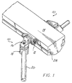
- Fig. 1 is a coupling apparatus 10 of the present invention.
- the coupling apparatus 10 has a base member 12 that is releasably connectable to a slide mount 14 for adjustably locating the coupling apparatus 10 along a predetermined path of travel.
- the base member 12 is adjustably connected to a midportion 16 of the coupling apparatus 10
- the midportion 16 is adjustably connected to an end member 18 of the coupling apparatus 10 .
- All three members 12, 16, 18 of the coupling apparatus 10 are preferably fabricated from cast aluminum to create a light weight, strong part that does not require machining.
- the present invention is not limited to cast aluminum, but rather, the coupling apparatus 10 may be fabricated from any material having the strength necessary to support the tooling assemblies and workpieces utilized in conjunction with the coupling apparatus 10 .
- the end member 18 is releasably connectable to a tooling rod, such as a boom rod 20 or a spline rod 84 , that is typically utilized for carrying workpiece handling fixtures such as vacuum cups, clamps (not shown) and/or grippers 106 .
- a tooling rod such as a boom rod 20 or a spline rod 84
- workpiece handling fixtures such as vacuum cups, clamps (not shown) and/or grippers 106 .
- the base member 12 has a substantially diamond shape configuration, as seen in Figs. 1 and 2.
- An aperture 22 is provided at each end of the base member 12 , and the apertures 22 receive threaded fasteners 24 that each threadingly engage a nut 26 on the opposite side of the base member 12 .
- the nuts 26 are received and captured within a slot 28 provided in the slide mount 14 .
- the slot 28 has a substantially C-shaped configuration so that the nuts 26 remain captured within the slot 28 while providing the fasteners 24 access to the nuts 26 through the opening in the C-shaped slot 28 .
- the C-shaped slot 28 extends substantially linearly along the slide mount 14 .
- the base member 12 provides a first contoured surface 30 on the front side 32 of the base member 12 .
- the contoured surface 30 is substantially circular and slightly raised from the front side 32 of the base member 12 .
- the contoured surface 30 has V-shaped teeth 34 formed therein which extend radially outward from a first axis 36 of the contoured surface 30 .
- the V-shaped teeth 34 are circumferentially adjacent one another so that as the V-shaped teeth 34 extend radially outward, the teeth 34 become wider to form a substantially concentric and uniform surface.
- the midportion 16 provides a second contoured surface 38 that matingly engages the contoured surface 30 of the base member 12 .
- the contoured surface 38 of the midportion 16 is substantially similar to the contoured surface 30 of the base member 12 in that the contoured surface 38 of the midportion 16 has a substantially circular surface having V-shaped teeth 40 extending radially outward from the first axis 36 .
- the contoured surfaces 30, 38 matingly engage by having the raised portions of the V-shaped teeth 34, 40 matingly engage valleys or lower portions of the V-shaped teeth 40, 34 of the opposing contoured surface 38, 30 .
- Both the base member 12 and the midportion 16 provide apertures 42, 43, respectively, along the first axis 36 for receiving a fastener 44 that extends through midportion 16 and base member 12 and is threadingly received by a threaded nut 36 that is captured within the slot 28 of the slide mount 14 .
- the fastener 44 and the nut 46 connect and secure the midportion 16 to the base member 12 by ensuring that the contoured surfaces 30, 38 maintain their engagement. This type of circular mating engagement without interference from neighboring parts allows for complete 360° orbital adjustment of the midportion 16 about the first axis 36 relative to the base member 12 .
- the midportion 16 is also rotatably adjustable about a second axis 47 with respect to the end member 18 by having a third contoured surface 48 of the midportion 16 matingly engage a fourth contoured surface 50 of the end member 18 .
- the contoured surfaces 48 , 50 of the midportion 16 and the end member 18 are substantially similar to the contoured surfaces 30, 38 provided between the base member 12 and the midportion 16 , respectively, in that the contoured surfaces 48, 50 both provide substantially V-shaped teeth 49, 51 that extend radially outward from the second axis 47 .
- this type of circular mating engagement without interference from neighboring parts allows for complete 360° orbital adjustment of the midportion 16 about the second axis 47 with respect to the end member 18 .
- the second contoured surface 38 and the third contoured surface 48 of the midportion 16 are integrally formed at each end of the midportion 16 and are offset from one another at a substantially 90° angle.
- the backsides 53 of the contoured surfaces 38, 48 are connected and supported by a substantially triangular webbing or structural support 52 that is integral with and extends between the backsides 53 of the contoured surfaces 38, 48.
- the structural support 52 has an aperture or cavity 55 which extends along the first axis 36 and the second axis 47 .
- the aperture or cavity 55 is in communication with the aperture 43 in contoured surface 38 of the midportion 16 and an aperture 57 in contoured surface 48 of the midportion 16.
- the aperture 55 extends outward from the structural support 52 at the intersection of the first and second axes 36, 47 to form a substantially oval shaped opening 62 on an outer surface 64 of the structural support 52 .
- the substantially oval shaped opening 62 in the structural support 52 provides access to fasteners 44, 54 along the first and second axes 36, 47, respectively, and allows for the heads of the fasteners 44, 54 to be housed within the cavity 55 of the structural support 52 .
- a threaded nut 56 threadingly receives the fastener 54 and connects and secures the midportion 16 to the end member 18 by maintaining engagement between the contoured surfaces 48, 50 of the midportion 16 and the end member 18 .
- the end member 18 preferably has a substantially square body 66 having rounded comers with one of its sides being substantially arcuate.
- a top surface 68 of the end member 18 has the contoured surface 50 formed therein with an aperture 70 extending through the end member 18 along the second axis 47 .
- a second aperture 58 substantially perpendicular to said second axis 47 , is formed through a sidewall 72 of the end member 18 and is designed to receive an end of the boom rod 20 .
- the boom rod 20 has an aperture 60 extending therethrough for receiving the fastener 54 that releasably connects the midportion 16 to the end member 18 .
- the aperture 60 in the boom rod 20 receives the fastener 54 by having the centerline axis of the aperture 60 correspondingly align with the second axis 47 .
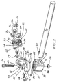
- the coupling apparatus 10 may be expanded to provide further range and flexibility, as shown in Figs. 3-9.
- the same base member 12 utilized in the preferred embodiment is adjustably connected to the slide mount 14 in the same manner described n the preferred embodiment.
- the base member 12 is adjustably connected to a midportion 73 and an end member 74 wherein the midportion 73 and the end member 74 are integrally connected.
- the end member 74 matingly engages and is adjustably connected to one end of the first spline rod 84.
- the opposite end of the spline rod 84 is connected to a spline bracket 86 which in turn is connected to a second spline rod 102 .
- a workpiece mounting bracket 75 having components similar to base member 12 , midportion 73 , and end member 74 , is utilized to connect a workpiece handling device or gripper 106 to the second spline rod 102 .
- the midportion 73 is structurally similar to the midportion 16 described in the previous embodiment except that the midportion 73 is integrally connected to the end member 74 by a narrowing neck portion 81 .
- the midportion 73 has a second contoured surface 77 that matingly engages the first contoured surface 38 of the base member 12 .
- the first and second contoured surfaces 38, 77 are preferably in the form of V-shaped serrated teeth as described in the preferred embodiment.
- Fastener 44 releasably connects the first and second contoured surfaces 38, 77 .
- the releasable connection allows for rotational adjustment of the midportion 73 relative to the base member 12 about a first rotational axis 79 .
- the midportion 73 provides a type of elbow 69 , similar to the structural support 52 described in the preferred embodiment.
- An aperture 71 similar to aperture 55 in the preferred embodiment, extends through the backside of the elbow 69 to provide access to apertures (not shown) that receive fastener 44 for connecting the midportion 73 and the base member 121 and receive fastener 54 for connecting the end member 74 to the first spline rod 84 .
- the aperture 71 also provides a housing for the heads of fasteners 44, 54 .
- the end member 74 matingly engages and is adjustably connected to the first spline rod 84 by providing an upper portion 76 and a lower portion 78 wherein the upper and lower portions 76, 78 are separate structures that are hinged at one of their ends by a pivot pin 80 , as seen in Fig. 4.
- the upper portion 76 of the end member 74 is integrally connected to the midportion 73 via narrowing neck portion 81 , and fastener 54 extends through the midportion 73 , neck portion 81 , and upper and lower portions 76, 78 to connect the upper and lower portions 76, 78 opposite pivot pin 80 .
- the end member 74 also provides an aperture 82 extending therethrough wherein both the upper portion 76 and the lower portion 78 of the end member 74 each define one-half of aperture 82 .
- the upper portion 76 of the end member 74 provides a plurality of integral teeth 85 , preferably four, that extend into aperture 82 to matingly engage splines 83 formed in the first spline rod 84 , as seen in Fig. 5.
- the engagement of the teeth 85 with the splines 83 of the spline rod 84 prevent the spline rod 84 from rotating relative to its longitudinal axis or second rotational axis 95 , as seen in Fig. 4 .
- Fastener 54 maintains the relative position of the first spline rod 84 relative to the end member 74 by securing the upper and lower portions 76, 78 of the end member 74 against the first spline rod 84 .
- the fastener 54 may be loosened to allow the upper and lower portions 76, 78 of the end member 74 to pivot outwardly away from spline rod 84 .
- the spline rod 84 may then be rotatably adjusted about the second rotational axis 95 to a predetermined position wherein fastener 54 is then tightened to secure the spline rod 84 in the end member 74 .
- the midportion 73 is integrally connected to the end member 74 by narrowing neck portion 81 , and therefore, the midportion 73 cannot be adjusted relative to end member 74 .
- the midportion 73 and the end member 74 may be fabricated so that the first and second rotational axes 79, 95 are substantially parallel, as seen in Fig. 3, or the midportion 73 and the end member 74 may be designed so that the first and second rotational axes 79, 95 are substantially perpendicular, as seen in Fig. 4.
- the base member 12 , midportion 73 , and end member 74 are preferably fabricated from cast aluminum or some other high strength, lightweight material to provide a lightweight, strong part that does not require machining.
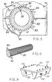
- the spline rod 84 comprises a hollow tubular configuration fabricated from an aluminum extrusion.
- the tubular extension and aluminum material provide for a lightweight, relatively inexpensive part.
- the tubular spline rod 84 has a plurality of splines 83 extending radially outward from the longitudinal axis of the spline rod 84 .
- the splines 83 are preferably spaced at 15 degree increments to provide 15 degree radial incremental rotational adjustment of the spline rod 84 .
- the spline rod 84 provides a mark 87 on one of its splines 83 to indicate where the spline rod 84 is mounted relative to the end member 74 .
- the end member 74 provides a plurality of indicia 89 formed on the face of the end member 74 adjacent the aperture 82 wherein the indicia 89 provide reference calibrations incrementally spaced every 15 degrees.
- the position of the marked spline 87 relative to the indicia 89 on the end member 74 may be recorded so that after adjusting other portions of the coupling apparatus 10 , the user can return the coupling apparatus 10 to its previous position.
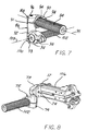
- the spline bracket 86 may be utilized to increase the flexibility and the range of the coupling apparatus 10 , as seen in Figs. 3 and 7.
- the spline bracket 86 is similar to a pair of end members 74 that are integrally connected and axially spaced.
- the spline bracket 86 provides a first portion 88 and a second portion 100 each having an upper and lower section 90, 91, 92, 93, respectively.
- Each upper and lower section 90-93 of the first and second portions 88, 100 are pivotally connected by a pivot pin 98 .
- the upper and lower sections 90-93 each define an aperture 94 for matingly engaging and adjustably connecting the opposite end or second end of the first spline rod 84 and a first end of the second spline rod 102 , respectively, wherein the second spline rod 102 is substantially identical to the first spline rod 88 .
- Both upper sections 90, 92 of the first and second portions 88, 100 provide integral teeth 85 , preferably four teeth, which extend into their respective apertures 94 for engaging the first and second spline rods 84, 102 .
- the lower section 91 of the first portion 88 and the upper section 92 of the second portion 100 of the spline bracket 86 are integrally connected by a tubular section 101 .
- a single fastener 96 extends the length of the spline bracket 86 by passing through the upper and lower sections 90-93 of the first and second portions 88, 100 opposite the pivot pins 98 to adjustably connect the spline rods 84, 102 to the spline bracket 86 .
- the upper and lower sections 90-93 of the first and second portions 88, 100 of spline bracket 86 may be pivoted away from the first and second spline rods 84, 102 to allow the spline rods 84, 102 to be rotatably adjusted about the second axis 95 and a third axis 103 , respectively.
- the first and second portions 88, 100 of the spline bracket 86 are rotated substantially 90° relative to one another so that the second and third axes 95, 103 are substantially perpendicular to one another.
- the portions of the spline bracket 86 that are adjacent the apertures 94 may include indicia 89 that are similarly provided on end member 74 .
- a marked spline 87 is utilized to record the position of the spline rods 84, 102 relative to the first and second portions 88, 100 of the spline bracket 86 .
- the workpiece mounting bracket 75 is connected to the opposite end or second end of the second spline rod 102, as seen in Fig. 8, wherein the first end of the second spline rod 102 is connected to the spline bracket 86 , as previously described.
- the workpiece mounting bracket 75 is substantially similar to the base member 12 , midportion 73 , and end member 74 , as previously described.
- the end member 74 matingly engages and is adjustably connected to the second end of the second spline rod 102 .
- the base member 12 is connected to the workpiece handling device 106 by fasteners 24 .
- a saddle mount 110 is shown attached to the slide mount 14 , as seen in Figs. 9-10.
- the saddle mount 110 is designed to be the main interface between the robot or manipulator.
- the saddle mount 110 provides a plurality of fasteners 112,113 for connecting the saddle mount 110 to the base member and for connecting the saddle mount 110 to the manipulator or robot, respectively.
- the coupling apparatus 10 may be adjusted along several axes of movement.
- the entire coupling apparatus 10 may be adjusted along the linear path of travel of the slide mount 14 by loosening the fasteners 24, 44 from the nuts 26, 46, respectively, and sliding the base member 12 along the slide mount 14.
- the coupling apparatus 10 moves with the base member 12 until the proper location is determined.
- the fasteners 24, 44 are then threaded into their respective nuts 26, 46 until the base member 12 is secured to the slide mount 14 .
- the midportion 16 may be rotatably adjusted with respect to the base member 12 along the first rotational axis 36 by loosening the fastener 44 from the nut 46 .
- the fastener 44 must be loosened far enough to allow the opposing V-shaped teeth 34, 40 of the contoured surfaces 30, 38 respectively, to rotate with respect to one another.
- the fastener 44 is threaded into the nut 46 until the midportion 16 is secured to the base member 12 . Rotational movement of the midportion 16 with respect to the base member 12 is prohibited by maintaining engagement between the V-shaped teeth 34, 40 of the contoured surfaces 30, 38.
- the relative positioning of the midportion 73 and base member 12 may be recorded by noting the position of the mark on the base member 12 with the indicia formed on the midportion 73 .
- the fastener 54 is loosened from the nut 56 until the V-shaped teeth 49, 51 of the contoured surfaces 48, 50 are allowed to rotate with respect to one another without engaging peaks of the opposing V-shaped teeth 49, 51 .
- the fastener 54 is threaded into the associated nut 56 until the end member 18 is secured to the midportion 16 . Relative rotational movement of the midportion 16 with respect to the end member 18 is prohibited by maintaining engagement between the V-shaped teeth 49, 51 of the contoured surfaces 48, 50 .
- the boom rod 20 may be removed or changed by unthreading the fastener 54 from the corresponding nut 56 and removing the fastener 54 from aperture 60 provided in the boom rod 20 .
- the boom rod 20 may then be removed and/or replaced with a different boom rod (not shown) wherein the fastener 54 is reinserted through a similar corresponding aperture provided in the replacement boom rod.
- the fastener 54 is threaded into the associated nut 56 until the boom rod 20 is secure in the end member 18 , and the end member 18 is secured to the midportion 16 .
- the midportion 73 and the end member 74 are integrally connected, and therefore, the midportion 73 and the end member 74 cannot be adjusted with respect to one another.
- the end member 74 does provide for rotational adjustment of the first spline rod 84 about the second rotational axis 95 by loosening fastener 54 to allow the teeth 85 in the upper portion 76 of the end member 74 to disengage the splines 83 of the first spline rod 84 .
- the spline rod 84 may then be rotated and adjusted by observing where the marked spline 87 on the spline rod 84 is located relative to the indicia 89 on the end member 74 .
- the position of the marked spline 87 may then be recorded to assure the repeatability of the positioning of the coupling apparatus 10 .
- the spline bracket 86 and the first and second spline rods 84, 102 are adjusted in a similar manner.
- the fastener 96 in the spline bracket 86 is loosened to allow the first and second spline rods 84, 102 to be rotated relative to the spline bracket 86 , and the fastener 96 is tightened to secure the first and second spline rods 84, 102 relative to the spline bracket 86 .
- the positions of the marked splines 87 on the first and second spline rods 84,102 relative to the indicia 89 on the spline bracket 86 may be recorded to assure the repeatability of the position of the spline rods 84, 102 relative to the spline bracket 86 .
- the workpiece mounting bracket 75 may be adjusted in the same manner as described by the base member 12 , midportion 73 , and the end member 74 of the alternative embodiment.
- the end member 74 is connected to the second end of the second spline rod 102
- the base member 12 is connected to the workpiece handling device 106 .
- the position of the workpiece handling device 106 may be rotatably adjusted by rotating the base member 12 with respect to the midportion 73 ..
- the same V-shaped serrated teeth engagement is utilized, as described in the preferred embodiment.
Landscapes
- Engineering & Computer Science (AREA)
- General Engineering & Computer Science (AREA)
- Mechanical Engineering (AREA)
- Robotics (AREA)
- Mutual Connection Of Rods And Tubes (AREA)
- Jigs For Machine Tools (AREA)
- Gripping Jigs, Holding Jigs, And Positioning Jigs (AREA)
- Orthopedics, Nursing, And Contraception (AREA)
Applications Claiming Priority (4)
| Application Number | Priority Date | Filing Date | Title |
|---|---|---|---|
| US458519 | 1999-12-13 | ||
| US09/458,519 US6409411B1 (en) | 1999-12-13 | 1999-12-13 | Modular tooling coupling apparatus |
| US19508600P | 2000-04-06 | 2000-04-06 | |
| US195086P | 2000-04-06 |
Publications (2)
| Publication Number | Publication Date |
|---|---|
| EP1108945A1 true EP1108945A1 (fr) | 2001-06-20 |
| EP1108945B1 EP1108945B1 (fr) | 2003-04-09 |
Family
ID=26890686
Family Applications (1)
| Application Number | Title | Priority Date | Filing Date |
|---|---|---|---|
| EP00311030A Expired - Lifetime EP1108945B1 (fr) | 1999-12-13 | 2000-12-11 | Dispositif d'accouplage d'outils modulaire |
Country Status (4)
| Country | Link |
|---|---|
| US (1) | US6619872B2 (fr) |
| EP (1) | EP1108945B1 (fr) |
| DE (1) | DE60002028T2 (fr) |
| ES (1) | ES2212764T3 (fr) |
Cited By (11)
| Publication number | Priority date | Publication date | Assignee | Title |
|---|---|---|---|---|
| EP1252979A1 (fr) * | 2001-04-28 | 2002-10-30 | KUKA Roboter GmbH | Dispositif de soutien de câbles sur un bras de robot comprenant des moyens d'encliquetage |
| FR2855089A1 (fr) * | 2003-05-21 | 2004-11-26 | A M G | Organe prehenseur pour la retenue d'une piece a deplacer par un manipulateur, agence en structure etagee comprenant une poutre sur laquelle sont articules des bras porteurs d'une tete de retenue |
| WO2004103652A3 (fr) * | 2003-05-21 | 2005-05-06 | Amg Soc | Organe prehenseur pour la retenue d’une piece a deplacer par un manipulateur, agence en structure etagee comprenant une poutre sur laquelle sont articules des bras porteurs d’une tete de retenue |
| FR2864920A1 (fr) * | 2004-01-09 | 2005-07-15 | Bruno Leneveu | Dispositif pour l'assemblage d'elements standar destine a la realisation de structures mecaniques de precision |
| EP1729054A3 (fr) * | 2005-06-01 | 2007-05-16 | Norgren Automotive Inc. | Dispositif de réglage discret d'un accouplement d'outillage modulaire |
| EP1867445A1 (fr) * | 2006-06-15 | 2007-12-19 | Norgren Automotive Inc. | Dispositif d'assemblage multiaxe de réglage réglable d'un accouplement d'outillage modulaire |
| WO2007120795A3 (fr) * | 2006-04-13 | 2008-04-17 | Norgren Automotive Inc | Appareil permettant de positionner et soutenir avec précision un outillage modulaire |
| WO2012109351A1 (fr) * | 2011-02-08 | 2012-08-16 | Norgren Automation Solutions, Inc. | Appareil d'outillage modulaire qui présente des dents serrées pour permettre un réglage orbital et linéaire |
| EP2778492A1 (fr) * | 2013-03-15 | 2014-09-17 | UNIVER S.p.A. | Liaison de deux pièces d'adaptation d'un dispositif de support modulaire |
| US9095946B2 (en) | 2011-02-08 | 2015-08-04 | Norgren Automation Solutions, Llc | Modular tooling apparatus having serrated teeth for orbital and linear adjustment |
| CN113296332A (zh) * | 2021-05-11 | 2021-08-24 | 通化师范学院 | 一种广播电视编导用便携式背景幕布 |
Families Citing this family (42)
| Publication number | Priority date | Publication date | Assignee | Title |
|---|---|---|---|---|
| ITTO20020421A1 (it) * | 2002-05-17 | 2003-11-17 | Comau Spa | Attrezzatura utilizzabile da un robot industriale per l'afferramento di pezzi o gruppi in lavorazione od assemblaggio,con struttura modulare |
| ITTO20020422A1 (it) * | 2002-05-17 | 2003-11-17 | Comau Spa | Attrezzatura utilizzabile da un robot industriale per l'afferramento di pezzi o gruppi in lavorazione od assemblaggio,con struttura scomponi |
| US7367740B2 (en) * | 2003-04-10 | 2008-05-06 | Pedrag Lazic | Mechanically lockable universal joint and structures employing such joint |
| ITMI20032012A1 (it) * | 2003-10-16 | 2005-04-17 | Elesa Spa | Sistema di supporto a morsetti per dispositivi e componenti elettrici, elettronici, ottici e meccanici |
| DE20318749U1 (de) * | 2003-12-04 | 2004-03-11 | Kahl, Helmut | Spannvorrichtung zum Anbringen von Bauteilen an Vorrichtungen |
| US7461826B2 (en) * | 2004-11-16 | 2008-12-09 | Carnevali Jeffrey D | Lift truck base |
| US7523904B2 (en) * | 2004-11-16 | 2009-04-28 | Carnevali Jeffrey D | Locking ratchet base |
| US20060102823A1 (en) * | 2004-11-16 | 2006-05-18 | Carnevali Jeffrey D | Locking ratchet base |
| US20080226427A1 (en) * | 2005-07-06 | 2008-09-18 | Norgren Automotive, Inc. | Apparatus for accurately positioning and supporting modular tooling |
| DE102005036431B3 (de) * | 2005-08-03 | 2006-10-19 | Audi Ag | Modular aufbaubare Tragvorrichtung für Werkzeuge, insbesondere zur Verwendung im Karosseriebau der Kraftfahrzeugindustrie |
| DE102005053753A1 (de) * | 2005-11-10 | 2007-05-16 | Maquet Gmbh & Co Kg | Hydraulische Säulenklemmung |
| DE102005053754A1 (de) | 2005-11-10 | 2007-05-16 | Maquet Gmbh & Co Kg | Einrichtung zum Verstellen der Liegefläche eines Operationstisches |
| DE102005054175A1 (de) * | 2005-11-14 | 2007-05-16 | Maquet Gmbh & Co Kg | Gelenkanordnung zur Verbindung zweier Segmente einer Patientenlagerfläche |
| DE102005054174A1 (de) * | 2005-11-14 | 2007-05-16 | Maquet Gmbh & Co Kg | Patientenlagerfläche für einen Operationstisch |
| DE102005054230A1 (de) * | 2005-11-14 | 2007-05-24 | Maquet Gmbh & Co. Kg | Verfahren und Einrichtung zur bidirektionalen IR-Datenübertragung zwischen einem Operationstisch und einem Bediengerät |
| DE102005054224A1 (de) * | 2005-11-14 | 2007-05-16 | Maquet Gmbh & Co Kg | Patientenlagersystem |
| DE102005054223A1 (de) * | 2005-11-14 | 2007-05-16 | Maquet Gmbh & Co Kg | Einrichtung zum Verstellen eines Operationstisches |
| DE102005054221A1 (de) * | 2005-11-14 | 2007-05-16 | Maquet Gmbh & Co Kg | Patientenlagersystem |
| DE102005054222A1 (de) * | 2005-11-14 | 2007-05-16 | Maquet Gmbh & Co Kg | Operationstisch |
| US7394021B2 (en) * | 2006-04-20 | 2008-07-01 | Magno Jr Joey D | Rotatable liquid-tight conduit connector assembly |
| US7922137B2 (en) * | 2006-08-04 | 2011-04-12 | Innovative Office Products, Inc. | Laptop holder for extension arm |
| ITMI20062512A1 (it) * | 2006-12-27 | 2008-06-28 | Claudio Vicentelli | Dispositivo di giunzione per assiemi magnetici strutturali |
| US8146879B2 (en) * | 2010-08-18 | 2012-04-03 | Unique Product & Design Co., Ltd. | Umbrella holder |
| DE102011000205B4 (de) | 2011-01-18 | 2014-07-17 | Illinois Tool Works Inc. | Vorrichtung und Verfahren zum Reffen eines Schlauchfolienabschnitts |
| DE102011075451B4 (de) | 2011-05-06 | 2014-05-08 | Illinois Tool Works Inc. | Verfahren und Vorrichtung zum Aufreffen eines Schlauchfolienabschnitts auf die Refffinger einer Verpackungsanlage |
| FI124180B (fi) * | 2011-09-30 | 2014-04-15 | Illinois Tool Works | Menetelmä käärintäkoneen kuljetustilaan saattamiseksi sekä käärintäkone |
| FI125661B (en) | 2012-09-07 | 2015-12-31 | Signode Int Ip Holdings Llc | Method and apparatus for positioning corner guards on a load |
| US9821178B2 (en) | 2013-02-08 | 2017-11-21 | D B Industries, Llc | Bracket assembly |
| US9232836B1 (en) * | 2014-10-23 | 2016-01-12 | Jeffrey T. Zaccaro | Shade device |
| US9408073B2 (en) * | 2013-09-11 | 2016-08-02 | Oracle International Corporation | Proximity and behavior-based enterprise security using a mobile device |
| FI125411B (en) | 2013-10-31 | 2015-10-15 | Signode Internat Ip Holdings Llc | Method and Attachment Device for Attaching the End of a Wrapping Film Web to a Wrapping Machine, and a Wrapping Machine |
| CN103982758B (zh) * | 2014-05-05 | 2016-11-16 | 合肥聚能电物理高技术开发有限公司 | 一种超高真空环境下紧凑型高精度多维旋转机构 |
| DE102014106365B4 (de) | 2014-05-07 | 2017-06-14 | Lachenmeier Aps | Verpackungsverfahren zum Verpacken eines Gutes |
| US9377269B2 (en) * | 2014-11-03 | 2016-06-28 | K Tech Designs, L.L.C. | Apparatus for mounting a sidebar to an archery bow |
| DE102015101489A1 (de) | 2015-02-02 | 2016-08-04 | Signode Industrial Group Llc | Verpackungsvorrichtung und Verfahren zum Betrieb derselben |
| US9903144B2 (en) * | 2015-04-06 | 2018-02-27 | Jerrold A. Gibson | Door jam stopper device |
| US9933109B2 (en) | 2015-06-03 | 2018-04-03 | Dgm Enterprises Llc | Vibration resistant equipment mount |
| CN108618301B (zh) * | 2018-07-09 | 2024-01-30 | 云未科技有限公司 | 一种户外伞用旋转接头 |
| WO2020012267A1 (fr) * | 2018-07-11 | 2020-01-16 | 3-D Solutions Design Service, Llc | Outillage d'automatisation à tube coudé |
| CN112923964B (zh) * | 2021-01-25 | 2023-11-07 | 成都主导科技有限责任公司 | 一种轨道车辆检测系统的调节装置 |
| TWM630999U (zh) * | 2022-03-10 | 2022-08-21 | 信隆車料工業股份有限公司 | 車用把手之配件固定模組 |
| US11801793B1 (en) * | 2022-07-06 | 2023-10-31 | All Rite Products, Inc. | Directionally adjustable mounting system and related methods |
Citations (4)
| Publication number | Priority date | Publication date | Assignee | Title |
|---|---|---|---|---|
| GB2042056A (en) * | 1979-02-14 | 1980-09-17 | Pittas A C | Multi-setting mounting assembly for articles |
| US4547092A (en) * | 1984-02-21 | 1985-10-15 | Hamilton Industries | Accessory clamp for medical table |
| US4875651A (en) * | 1988-12-06 | 1989-10-24 | Wergin Dennis D | Transducer mounting device |
| US5538215A (en) * | 1994-11-15 | 1996-07-23 | Midmark Corporation | Siderail socket |
Family Cites Families (13)
| Publication number | Priority date | Publication date | Assignee | Title |
|---|---|---|---|---|
| US3205522A (en) | 1963-08-28 | 1965-09-14 | Karl P Then | Universally adjustable tool holder |
| US3799599A (en) | 1973-01-26 | 1974-03-26 | B Jordan | Fluorescent lamp handling device |
| US3922481A (en) | 1973-03-12 | 1975-11-25 | Chance Co Ab | Open configuration midspan electrical conductor spacer |
| US4447170A (en) | 1982-03-02 | 1984-05-08 | Ralph Holmes | Connection assembly for use with an articulated linkage system |
| US4474328A (en) | 1982-09-29 | 1984-10-02 | Virginia Hale | Variable lift sprinkler unit |
| US4986016A (en) | 1986-12-10 | 1991-01-22 | Wichman William J | Folding display frame with offset hub configuration |
| WO1994000699A1 (fr) * | 1992-06-24 | 1994-01-06 | D & D Group Pty Ltd | Dispositif d'engagement et element d'accouplement |
| US5520474A (en) | 1994-09-19 | 1996-05-28 | Liu; Yang-Ting | Adjustable coupling |
| US5547305A (en) | 1995-03-02 | 1996-08-20 | The Whitaker Corporation | Rapid, tool-less adjusting system for hotstick tooling |
| US5564852A (en) | 1995-03-29 | 1996-10-15 | Burndy Corporation | Adjustable hot stick adaptor |
| US5694818A (en) * | 1995-12-11 | 1997-12-09 | Nickipuck; Michael F. | Locking joint for a ratchet wrench |
| US6106181A (en) * | 1996-01-29 | 2000-08-22 | Rittal-Werk Rudolf Loh Gmbh & Co. Kg | Control apparatus with control panel |
| US6079682A (en) | 1998-12-23 | 2000-06-27 | Nokia Mobile Phones Limited | Apparatus for mounting a mobile device on a support surface |
-
2000
- 2000-12-11 ES ES00311030T patent/ES2212764T3/es not_active Expired - Lifetime
- 2000-12-11 EP EP00311030A patent/EP1108945B1/fr not_active Expired - Lifetime
- 2000-12-11 DE DE60002028T patent/DE60002028T2/de not_active Expired - Fee Related
- 2000-12-13 US US09/736,862 patent/US6619872B2/en not_active Expired - Lifetime
Patent Citations (4)
| Publication number | Priority date | Publication date | Assignee | Title |
|---|---|---|---|---|
| GB2042056A (en) * | 1979-02-14 | 1980-09-17 | Pittas A C | Multi-setting mounting assembly for articles |
| US4547092A (en) * | 1984-02-21 | 1985-10-15 | Hamilton Industries | Accessory clamp for medical table |
| US4875651A (en) * | 1988-12-06 | 1989-10-24 | Wergin Dennis D | Transducer mounting device |
| US5538215A (en) * | 1994-11-15 | 1996-07-23 | Midmark Corporation | Siderail socket |
Cited By (17)
| Publication number | Priority date | Publication date | Assignee | Title |
|---|---|---|---|---|
| EP1252979A1 (fr) * | 2001-04-28 | 2002-10-30 | KUKA Roboter GmbH | Dispositif de soutien de câbles sur un bras de robot comprenant des moyens d'encliquetage |
| FR2855089A1 (fr) * | 2003-05-21 | 2004-11-26 | A M G | Organe prehenseur pour la retenue d'une piece a deplacer par un manipulateur, agence en structure etagee comprenant une poutre sur laquelle sont articules des bras porteurs d'une tete de retenue |
| WO2004103652A3 (fr) * | 2003-05-21 | 2005-05-06 | Amg Soc | Organe prehenseur pour la retenue d’une piece a deplacer par un manipulateur, agence en structure etagee comprenant une poutre sur laquelle sont articules des bras porteurs d’une tete de retenue |
| FR2864920A1 (fr) * | 2004-01-09 | 2005-07-15 | Bruno Leneveu | Dispositif pour l'assemblage d'elements standar destine a la realisation de structures mecaniques de precision |
| WO2005075874A1 (fr) * | 2004-01-09 | 2005-08-18 | Bruno Leneveu | Dispositif pour l'assemblage d'elements standard destine a la realisation de structures mecanioues de precision |
| EP1729054A3 (fr) * | 2005-06-01 | 2007-05-16 | Norgren Automotive Inc. | Dispositif de réglage discret d'un accouplement d'outillage modulaire |
| US8162557B2 (en) | 2005-06-16 | 2012-04-24 | Norgren Automation Solutions, Llc | Multi-axis coupling apparatus for adjustably mounting modular tooling members |
| US8108978B2 (en) | 2005-07-06 | 2012-02-07 | Norgren Automation Solutions, Inc. | Apparatus for accurately positioning and supporting modular tooling |
| WO2007120795A3 (fr) * | 2006-04-13 | 2008-04-17 | Norgren Automotive Inc | Appareil permettant de positionner et soutenir avec précision un outillage modulaire |
| EP1867445A1 (fr) * | 2006-06-15 | 2007-12-19 | Norgren Automotive Inc. | Dispositif d'assemblage multiaxe de réglage réglable d'un accouplement d'outillage modulaire |
| WO2012109351A1 (fr) * | 2011-02-08 | 2012-08-16 | Norgren Automation Solutions, Inc. | Appareil d'outillage modulaire qui présente des dents serrées pour permettre un réglage orbital et linéaire |
| JP2014511282A (ja) * | 2011-02-08 | 2014-05-15 | ノルグレン オートメーション ソーリューションズ エルエルシー | 軌道及び線形の調整のためのギザギザの歯を有するモジュラ工具装置 |
| US9095946B2 (en) | 2011-02-08 | 2015-08-04 | Norgren Automation Solutions, Llc | Modular tooling apparatus having serrated teeth for orbital and linear adjustment |
| US9395032B2 (en) | 2011-02-08 | 2016-07-19 | Norgren Automation Solutions, Llc | Modular tooling apparatus having serrated teeth for orbital and linear adjustment |
| US9429187B2 (en) | 2011-02-08 | 2016-08-30 | Norgren Automation Solutions, Llc | Modular tooling apparatus having serrated teeth for orbital and linear adjustment |
| EP2778492A1 (fr) * | 2013-03-15 | 2014-09-17 | UNIVER S.p.A. | Liaison de deux pièces d'adaptation d'un dispositif de support modulaire |
| CN113296332A (zh) * | 2021-05-11 | 2021-08-24 | 通化师范学院 | 一种广播电视编导用便携式背景幕布 |
Also Published As
| Publication number | Publication date |
|---|---|
| DE60002028T2 (de) | 2003-10-16 |
| EP1108945B1 (fr) | 2003-04-09 |
| US20010004431A1 (en) | 2001-06-21 |
| ES2212764T3 (es) | 2004-08-01 |
| DE60002028D1 (de) | 2003-05-15 |
| US6619872B2 (en) | 2003-09-16 |
Similar Documents
| Publication | Publication Date | Title |
|---|---|---|
| US6619872B2 (en) | Modular tooling coupling apparatus | |
| US6409411B1 (en) | Modular tooling coupling apparatus | |
| US8162557B2 (en) | Multi-axis coupling apparatus for adjustably mounting modular tooling members | |
| JP5883037B2 (ja) | 回転及び直線方向の調整のためのギザギザの歯を有するモジュラ工具装置 | |
| US9429187B2 (en) | Modular tooling apparatus having serrated teeth for orbital and linear adjustment | |
| US5299847A (en) | Gripper assembly | |
| EP1729054A2 (fr) | Dispositif de réglage discret d'un accouplement d'outillage modulaire | |
| US8419309B2 (en) | Pivoting ball mount having four equally spaced contact points | |
| USRE36883E (en) | Holder for a flashlight | |
| EP1166955A3 (fr) | Système pour attacher / détacher une pièce à usiner sur un support de fixation | |
| US8172234B2 (en) | Collet tool holder having adjustable axis | |
| US9321180B2 (en) | Industrial robot device, an industrial robot and a method for manipulating objects | |
| US5261715A (en) | Work holder support apparatus | |
| GB2083795A (en) | Manipulator mechanisms | |
| US5836575A (en) | Wafer manual handpick station | |
| US5918867A (en) | Multiple axis mounting unit | |
| US5560449A (en) | Adjustable trestle sawhorse | |
| US20080226427A1 (en) | Apparatus for accurately positioning and supporting modular tooling | |
| EP0479740B1 (fr) | Dispositif pour suspendre un robot à une poutre de support | |
| JP4249530B2 (ja) | パラレルメカニズム利用の位置決め装置 | |
| US4750699A (en) | Dial test indicator holder | |
| US7775495B2 (en) | Adapter assembly including telescoping links | |
| CA2601726A1 (fr) | Dispositif adaptateur avec elements de support destine a un materiel de manutention automatisee | |
| SE463402B (sv) | Verktyg foer positionering och fasthaallning av arbetsstycken | |
| CA2062712A1 (fr) | Poste de reparation de moteur marin |
Legal Events
| Date | Code | Title | Description |
|---|---|---|---|
| PUAI | Public reference made under article 153(3) epc to a published international application that has entered the european phase |
Free format text: ORIGINAL CODE: 0009012 |
|
| AK | Designated contracting states |
Kind code of ref document: A1 Designated state(s): DE ES FR GB IT SE |
|
| AX | Request for extension of the european patent |
Free format text: AL;LT;LV;MK;RO;SI |
|
| 17P | Request for examination filed |
Effective date: 20010730 |
|
| AKX | Designation fees paid |
Free format text: DE ES FR GB IT SE |
|
| 17Q | First examination report despatched |
Effective date: 20020204 |
|
| GRAH | Despatch of communication of intention to grant a patent |
Free format text: ORIGINAL CODE: EPIDOS IGRA |
|
| GRAH | Despatch of communication of intention to grant a patent |
Free format text: ORIGINAL CODE: EPIDOS IGRA |
|
| GRAA | (expected) grant |
Free format text: ORIGINAL CODE: 0009210 |
|
| AK | Designated contracting states |
Designated state(s): DE ES FR GB IT SE |
|
| REG | Reference to a national code |
Ref country code: GB Ref legal event code: FG4D |
|
| REG | Reference to a national code |
Ref country code: SE Ref legal event code: TRGR |
|
| ET | Fr: translation filed | ||
| PG25 | Lapsed in a contracting state [announced via postgrant information from national office to epo] |
Ref country code: SE Free format text: LAPSE BECAUSE OF NON-PAYMENT OF DUE FEES Effective date: 20031212 Ref country code: ES Free format text: LAPSE BECAUSE OF NON-PAYMENT OF DUE FEES Effective date: 20031212 |
|
| PLBE | No opposition filed within time limit |
Free format text: ORIGINAL CODE: 0009261 |
|
| STAA | Information on the status of an ep patent application or granted ep patent |
Free format text: STATUS: NO OPPOSITION FILED WITHIN TIME LIMIT |
|
| 26N | No opposition filed |
Effective date: 20040112 |
|
| PG25 | Lapsed in a contracting state [announced via postgrant information from national office to epo] |
Ref country code: DE Free format text: LAPSE BECAUSE OF NON-PAYMENT OF DUE FEES Effective date: 20040701 |
|
| REG | Reference to a national code |
Ref country code: ES Ref legal event code: FG2A Ref document number: 2212764 Country of ref document: ES Kind code of ref document: T3 |
|
| EUG | Se: european patent has lapsed | ||
| PG25 | Lapsed in a contracting state [announced via postgrant information from national office to epo] |
Ref country code: FR Free format text: LAPSE BECAUSE OF NON-PAYMENT OF DUE FEES Effective date: 20040831 |
|
| REG | Reference to a national code |
Ref country code: FR Ref legal event code: ST |
|
| PG25 | Lapsed in a contracting state [announced via postgrant information from national office to epo] |
Ref country code: GB Free format text: LAPSE BECAUSE OF NON-PAYMENT OF DUE FEES Effective date: 20041211 |
|
| REG | Reference to a national code |
Ref country code: ES Ref legal event code: FD2A Effective date: 20031212 |
|
| GBPC | Gb: european patent ceased through non-payment of renewal fee |
Effective date: 20041211 |
|
| PG25 | Lapsed in a contracting state [announced via postgrant information from national office to epo] |
Ref country code: IT Free format text: LAPSE BECAUSE OF NON-PAYMENT OF DUE FEES;WARNING: LAPSES OF ITALIAN PATENTS WITH EFFECTIVE DATE BEFORE 2007 MAY HAVE OCCURRED AT ANY TIME BEFORE 2007. THE CORRECT EFFECTIVE DATE MAY BE DIFFERENT FROM THE ONE RECORDED. Effective date: 20051211 |