EP1109131A2 - Bildverarbeitungsgerät - Google Patents
Bildverarbeitungsgerät Download PDFInfo
- Publication number
- EP1109131A2 EP1109131A2 EP00310509A EP00310509A EP1109131A2 EP 1109131 A2 EP1109131 A2 EP 1109131A2 EP 00310509 A EP00310509 A EP 00310509A EP 00310509 A EP00310509 A EP 00310509A EP 1109131 A2 EP1109131 A2 EP 1109131A2
- Authority
- EP
- European Patent Office
- Prior art keywords
- voxel
- image
- images
- voxels
- space
- Prior art date
- Legal status (The legal status is an assumption and is not a legal conclusion. Google has not performed a legal analysis and makes no representation as to the accuracy of the status listed.)
- Withdrawn
Links
Images


Classifications
-
- G—PHYSICS
- G06—COMPUTING OR CALCULATING; COUNTING
- G06T—IMAGE DATA PROCESSING OR GENERATION, IN GENERAL
- G06T15/00—Three-dimensional [3D] image rendering
- G06T15/10—Geometric effects
-
- G—PHYSICS
- G06—COMPUTING OR CALCULATING; COUNTING
- G06T—IMAGE DATA PROCESSING OR GENERATION, IN GENERAL
- G06T17/00—Three-dimensional [3D] modelling for computer graphics
- G06T17/10—Constructive solid geometry [CSG] using solid primitives, e.g. cylinders, cubes
-
- G—PHYSICS
- G06—COMPUTING OR CALCULATING; COUNTING
- G06T—IMAGE DATA PROCESSING OR GENERATION, IN GENERAL
- G06T7/00—Image analysis
- G06T7/50—Depth or shape recovery
- G06T7/55—Depth or shape recovery from multiple images
-
- G—PHYSICS
- G06—COMPUTING OR CALCULATING; COUNTING
- G06T—IMAGE DATA PROCESSING OR GENERATION, IN GENERAL
- G06T2200/00—Indexing scheme for image data processing or generation, in general
- G06T2200/08—Indexing scheme for image data processing or generation, in general involving all processing steps from image acquisition to 3D model generation
Definitions
- This invention relates to an image processing apparatus and method, in particular, this invention relates to an image processing apparatus and method for use in the creation of a three-dimensional computer model of a real-life object from two-dimensional image data representing different views of the object to be modelled.
- this image data will consist of a set of still images or video frames recorded at different relative orientations or positions of the object and the recording camera.
- a three-dimensional object surface is generated from the set of image data and data defining the relative positions or orientations at which each of the images was recorded.
- One known way of generating a three-dimensional object surface from the image data is to use a technique known as "voxel carving” which is described in detail in a paper entitled “Rapid Octree Construction from Image Sequences” by Richard Szeliski published in CVGIP: Image Understanding Vol. 58, No. 1, July 1993 at pages 23-32.
- voxel carving a technique known as "voxel carving” which is described in detail in a paper entitled “Rapid Octree Construction from Image Sequences” by Richard Szeliski published in CVGIP: Image Understanding Vol. 58, No. 1, July 1993 at pages 23-32.
- a number of images of the object whose three-dimensional surface is to be modelled are produced such that each image shows a silhouette of the object surrounded by a background.
- the relative orientation between the object and the camera position at which each image was taken together with characteristics of the camera are used to determine the relative location and orientation of each image relative to a model volume or space which is divided into subsidiary volume elements or voxels to form a voxel space.
- Each non-occluded voxel is then projected into the images.
- Voxels that project into background portions of the images are removed from the voxel space. This procedure continues until no background voxels remain.
- the surface voxels of the voxel space should define the outline or silhouette of the object shown in the images.
- the above-described technique works satisfactorily where there is a well-defined boundary between the object and the background in the image, difficulties can arise where the boundary between the object and the background is ill-defined or difficult to distinguish because, for example, there is insufficient distinction in colour or brightness between the background and object pixels in the images.
- the above-described technique works well only when the conditions under which the images are acquired are well-controlled so that there is a clearly distinguishable boundary between the edge of the object and the background in each image.
- This technique relies on the fact that the viewpoint of each image or photograph is known in a common 3D world reference frame and that scene radiance follows a known, locally computable radiance function, that is so that effects such as shadows, transparencies and inter-reflections can be ignored.
- the three-dimensional model space is again divided into voxels.
- a non-occluded voxel is then projected into each image in turn.
- the colour of the patch of pixels to which the voxel projects is determined for each image. If the colours are different or not consistent, then it is determined that that voxel does not form part of the 3D object's surface and that voxel is removed or discarded.
- Each non-occluded voxel is visited in turn and the process is repeated until the remaining non-occluded voxels are all photo or colour consistent.
- the initial voxel space needs to be defined relative to the object. If the initial voxel space is too large, then a large number of computations and a large number of voxels will need to be removed until the final 3D object surface is generated.
- This erroneous voxel removal will compound the error discussed above and may itself result in one or more other voxels being erroneously removed and so on. Indeed, this initial error in definition of the voxel space may lead to a catastrophic failure in that so many voxels may be erroneously removed that it is not possible to generate the 3D object's surface.
- the above described voxel colouring or space carving technique also relies on the individual pixel patches being formed of pixels of the same or very similar colours. If there is a variation in colour between the pixels of a pixel patch, then the photoconsistency check may not provide accurate results and it is possible that a voxel that actually forms part of the required 3D object surface (an 'object voxel') may be erroneously removed.
- the erroneous removal of that voxel may have knock-on effects so that further object voxels are erroneously removed. This erroneous removal may, in turn, cause erroneous removal of further voxels.
- the erroneous removal of a single voxel may, in certain cases, effectively cause a cascade or chain reaction and may cause the voxel colouring process to fail, that is it may be impossible to provide a 3D model of the object surface because too many (possibly even all) of the object voxels may be removed.
- each voxel in turn is projected into each of the images in which it is visible. Because of the computational power and time required, it is generally not possible to carry out this process using more than 20-30 images. Depending upon the nature of the object whose three dimensional surface is to be modelled, this number of images may be insufficient to provide a realistic 3D model of the object surface.
- the erroneous removal of a single voxel may, in certain cases, effectively cause a cascade or chain reaction and may cause the voxel colouring process to fail, that is it may be impossible to provide a 3D model of the object surface because too many (possibly even all) of the object voxels may be removed.
- the present invention provides image processing apparatus having processing means operable to define an initial voxel space from which a three-dimensional object surface is to be generated by defining the initial voxel space as the volume bounded by the intersection of a number of cones with each cone having its apex at a respective one of the focal points and having its surface defined by lines extending from the focal point through the boundary of the corresponding camera aperture or imaging area for a respective one of the images from which the three-dimensional object surface is to be generated.
- the present invention provides image processing apparatus having processing means operable to test whether a voxel forms part of a 3D object, the processing means being arranged, where it cannot determine whether a voxel forms part of the 3D object surface, to sub-divide that voxel into subsidiary voxels and to repeat the test for each of the subsidiary voxels. If desired, this sub-division may be continued until each subsidiary voxel projects only into a single pixel in each image.
- Such apparatus embodying the present invention should enable a more accurate determination of the 3D object surface even where there is significant colour variation within a pixel patch into which a voxel projects.
- the present invention provides image processing apparatus having processing means operable to determine, using a first set of image data, the photoconsistency of non-occluded voxels of an initial voxel space to provide a first 3D object surface and then to refine that first 3D object surface by checking the photoconsistency of non-occluded voxels of that first 3D object surface against image data for one or more further images.
- the present invention provides image processing apparatus having processing means operable to provide a 3D model of a surface of a 3D object by checking the photoconsistency of non-occluded voxels of an initial voxel space for a first set of image data, storing the results of that check as a first 3D object surface and then refining the first 3D object surface by checking the photoconsistency of non-occluded voxels using one or more further images of the object and one or more of the images used to produce the first 3D object surface.
- the processing means may be operable to repeat the refinement one or more further times adding one or more further images each time.
- the present invention provides image processing apparatus having processing means operable to provide a model of a 3D object surface by checking the photoconsistency of voxels of a voxel space using images of the object, and then to repeat that process using further images so as to further refine the 3D object surface model until a final 3D object surface model is produced, whereby the processing means is operable to use at least one additional image in each photoconsistency check and to store the 3D object surface generated by at least one of the previous photoconsistency checks before carrying out the next photoconsistency check so that, if the next photoconsistency check results in the erroneous removal of one or more object voxels, the processing means can return to the results of the stored previous photoconsistency check.
- the present invention provides image processing apparatus having processing means operable to provide a model of a 3D object surface by checking the photoconsistency of voxels of a voxel space using images of the object, and then to repeat that process using further images so as to further refine the 3D object surface model until a final 3D object surface model is produced, the processing means also being operable to store the image data for one or more of the images previously used for a photoconsistency check and to discard the oldest of the stored images and replace it with the newest used image each time the photoconsistency check is repeated so that the processing means is operable to store a running set of images thereby enabling a photoconsistency check to be carried out using the stored images together with a newly added image so that the processing means has available the raw image data for each of the stored images and not simply the 3D object surface that resulted from the previous photoconsistency check.
- Figure 1 schematically shows the components of a modular system in which the present invention may be embodied.
- These components can be effected as processor-implemented instructions, hardware or a combination thereof.
- the components are arranged to process data defining images (still or moving) of one or more objects in order to generate data defining a three-dimensional computer model of the object(s).
- the input image data may be received in a variety of ways, such as directly from one or more digital cameras, via a storage device such as a disk or CD ROM, by digitisation of photographs using a scanner, or by downloading image data from a database, for example via a datalink such as the Internet, etc.
- the generated 3D model data may be used to: display an image of the object(s) from a desired viewing position; control manufacturing equipment to manufacture a model of the object(s), for example by controlling cutting apparatus to cut material to the appropriate dimensions; perform processing to recognise the object(s), for example by comparing it to data stored in a database; carry out processing to measure the object(s), for example by taking absolute measurements to record the size of the object(s), or by comparing the model with models of the object(s) previously generated to determine changes therebetween; carry out processing so as to control a robot to navigate around the object(s); store information in a geographic information system (GIS) or other topographic database; or transmit the object data representing the model to a remote processing device for any such processing, either on a storage device or as a signal (for example, the data may be transmitted in virtual reality modelling language (VRML) format over the Internet, enabling it to be processed by a WWW browser); etc.
- GIS geographic information system
- VRML virtual reality modelling language
- the feature detection and matching module 2 is arranged to receive image data recorded by a still camera from different positions relative to the object(s) (the different positions being achieved by moving the camera and/or the object(s)). The received data is then processed in order to match features within the different images (that is, to identify points in the images which correspond to the same physical point on the object(s)).
- the feature detection and tracking module 4 is arranged to receive image data recorded by a video camera as the relative positions of the camera and object(s) are changed (by moving the video camera and/or the object(s)). As in the feature detection and matching module 2, the feature detection and tracking module 4 detects features, such as corners, in the images. However, the feature detection and tracking module 4 then tracks the detected features between frames of image data in order to determine the positions of the features in other images.
- the camera position calculation module 6 is arranged to use the features matched across images by the feature detection and matching module 2 or the feature detection and tracking module 4 to calculate the transformation between the camera positions at which the images were recorded and hence determine the orientation and position of the camera focal plane when each image was recorded.
- the feature detection and matching module 2 and the camera position calculation module 6 may be arranged to perform processing in an iterative manner. That is, using camera positions and orientations calculated by the camera position calculation module 6, the feature detection and matching module 2 may detect and match further features in the images using epipolar geometry in a conventional manner, and the further matched features may then be used by the camera position calculation module 6 to recalculate the camera positions and orientations.
- the image data need not be processed by the feature detection and matching module 2, the feature detection and tracking module 4, or the camera position calculation module 6.
- the images may be recorded by mounting a number of cameras on a calibrated rig arranged to hold the cameras in known positions relative to the object(s).
- Camera calibration module 10 is therefore provided to receive image data from a plurality of cameras at fixed positions showing the object(s) together with calibration markers, and to process the data to determine the positions of the cameras.
- the 3D object surface generation module 12 is arranged to receive image data showing the object(s) and data defining the positions at which the images were recorded, and to process the data to generate a 3D computer model representing the actual surface(s) of the object(s), such as a polygon mesh model.
- the texture data generation module 14 is arranged to generate texture data for rendering onto the surface model produced by the 3D object surface generation module 12.
- the texture data is generated from the input image data showing the object(s).
- the present invention may be embodied in particular as part of the 3D object surface generation module 12.
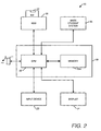
- FIG. 2 shows a block diagram of processing apparatus 20.
- the processing apparatus 20 comprises a main processing unit 21 having a central processing unit (CPU) 22 with associated memory (ROM and/or RAM) 22a.
- the CPU 22 is coupled to an input device 23 (which may consist, in known manner, of a keyboard and a pointing device such as a mouse), a display 24, a mass-storage system 25 such as a hard disc drive, and a removable disc drive (RDD) 26 for receiving a removable disc (RD) 27.
- the removable disc drive 26 may be arranged to receive removable disc 27 such as a floppy disc, a CD ROM or a writable CD ROM.
- the CPU 22 may also be coupled to an interface I for receiving signals S carrying processor implementable instructions and/or data.
- the interface may comprise, for example, a connection to a network such as the Internet, an intranet, a LAN (local area network) or a WAN (wide area network) or may comprise a data link to another processing apparatus, for example an infrared link.
- a network such as the Internet, an intranet, a LAN (local area network) or a WAN (wide area network)
- a data link to another processing apparatus for example an infrared link.
- the processing apparatus 20 is configured to form the 3D object surface generation module 12 shown in Figure 1 by means of processor implementable instructions and/or data stored in the memory 22a.
- Processor implementable instructions and/or data stored in the memory may also configure the apparatus to form any one or more of the other modules shown in Figure 1.
- These processor implementable instructions and/or data may be prestored in the memory 22a or may be supplied to the main processing unit 21 as a signal S via the interface I or on a removable disc 27 or may be supplied to the main processing unit 21 by any combination of these techniques.
- 3D object surface data resulting from use of the processing apparatus 20 in a manner to be described below may be stored in the mass-storage system 25 and may also be displayed on the display 24.
- the 3D object surface data may also be downloaded to a removable disc 27 or supplied as a signal S via the interface I.
- the 3D object surface data may be subsequently processed by the processing apparatus 20 when configured to operate as the texture data generation module 14 shown in Figure 1. Such further processing may, however, be carried out by another processing apparatus which receives the 3D object surface data via, for example, a removable disc 27 or as a signal S from the processing apparatus 20 shown in Figure 2.
- This data includes image data for each of the images of the object to be used to generate the 3D object surface.
- Each of the images is stored in the mass-storage system 25 as an array of pixel values with each pixel of each image being allocated a number identifying the colour of that pixel. Typically, for grey shades the number will be between 0 and 255 giving a possibility of 256 grey shades while for full colour the number will be between 0 and 255 for each primary colour (generally red, green and blue).
- the image data is accompanied by camera data representing the relative position and orientation with respect to the object of the camera positions at which the image was obtained and internal parameters of the camera or cameras such as the focal length and the dimensions of the imaging area or viewing window of the camera(s).
- This camera data may be obtained in the manner described above with reference to modules 2 and 6 in Figure 1 or modules 4 and 6 in Figure 1, or module 10 in Figure 1 or, as indicated by the arrow 8 in Figure 1, the position and relative orientation data may be obtained directly from known camera positions.
- the camera internal parameters may be prestored in the apparatus, input by the user using the input device 23 or determined as described in the aforementioned paper by Wiles and Davison (ISBN 0769501109).
- FIG. 3 shows a top level flowchart for illustrating generation of the 3D object surface from this data.
- step S1 an initial voxel space containing the required 3D object surface is defined by the CPU 22.
- the photoconsistency of each non-occluded voxel is checked in turn to determine the voxels defining the 3D object surface at step S2.
- the defined 3D object surface is then stored at step S3.
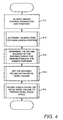
- Step S1 of Figure 3 will now be described in more detail with reference to the flowchart shown in Figure 4.
- the CPU 22 accesses the camera internal parameters and position data stored in the mass-storage system 25 ( Figure 2).
- the CPU 22 determines, using the camera internal parameters and positions, the viewing cone for each camera position.
- the CPU 22 determines the volume bounded by the intersection of the viewing cones of the camera positions, at step S14 the CPU 22 sets the bounded volume as the initial voxel volume and at step S15 the CPU 22 sub-divides the initial voxel space into cubic or right-parallelopipedal voxels arranged in a cubic, close-packed array so as to form the initial voxel space.
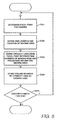
- FIG. 5 shows a flowchart illustrating in greater detail step S12 of Figure 4.
- the CPU 22 determines from the data stored in the mass-storage system 25, the focal point of the camera for the camera position for a first one of the stored images.
- the CPU 22 determines from the camera data stored in the mass-storage system the side lengths and location in three dimensional space of the imaging area relative to the focal point.
- the CPU defines rectilinear straight lines projecting from the determined focal point and each passing through and projecting beyond a respective different one of the corners of the imaging area.
- the CPU stores the volume bounded by the straight lines as the viewing cone by storing the relative orientations of the straight lines.
- the CPU 22 determines whether the viewing cone for another camera position needs to be determined. If the answer is yes, then the CPU 22 repeats steps S121 to S125 until the answer at step S125 is no when the CPU 22 proceeds to step S13 in Figure 4.
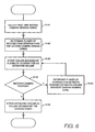
- FIG. 6 shows a flowchart illustrating in greater detail step S13 shown in Figure 4.
- the CPU 22 selects the stored data representing the viewing cones of first and second ones of the camera positions.
- the CPU 22 determines the planes of intersection between the first and second camera viewing cones using the stored data representing the straight lines defining the viewing cones.
- the CPU 22 stores the volume bounded by the planes of intersection of the viewing cones as an estimated volume.
- the CPU checks to see whether there is another camera position whose viewing cone intersection has not yet been determined.
- step S134 determines at step S135 the planes of intersection between the current estimated volume and the next camera position viewing cone and then stores the volume bounded by those planes of intersection as the new estimated volume at step S133. Steps S134, S135 and S133 are repeated until the answer at step S134 is no at which point the CPU stores the estimated volume as the volume bounded by the camera viewing cones at step S136 and returns to step S14 in Figure 4 at which the bounded volume is set as the initial voxel volume.
- FIG. 7 shows a flowchart illustrating in greater detail step S15 of Figure 4.
- the CPU 22 divides a volume or space containing the initial voxel space into cubic or right-parallelopipedal voxels arranged in a close-packed array. The CPU 22 then discards at step S152 any voxels lying outside the boundary of the determined initial voxel volume.
- the CPU 22 discards any voxels through which the boundary of the initial voxel volume passes and at step S154 stores the remaining voxels as the initial voxel space.
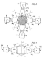
- Figures 8 and 9 show one example of a camera position arrangement to illustrate an example of an initial voxel space derived in the manner described above.
- the camera position arrangement consists of four camera positions A to D arranged in a single plane (the plane of the paper of Figure 8 in this example) and spaced apart by an angle of 90° relative to one another about a central axis X indicated by the dotted line in Figure 9.
- Each of the camera positions has a focal point F A to F D (in this example the focal lengths are all the same although this need not necessarily be the case) and an imaging area I A to I D (see Figure 10) defined by the camera aperture in the case of a camera using photographic film or by the CCD sensing area in the case of a CCD camera.
- the imaging areas I of all four cameras are the same.
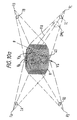
- Figures 8 to 10 show by way of the dashed lines the viewing cones VC A , VC B , VC C and VC D of each of the camera positions A to D.
- Figures 8 and 9 also show the relative locations of the images IM A , IM B , IM C and IM D produced at the camera positions A to D.
- the volume bounded by the intersection of the viewing cones of the camera positions A to D is identified by the reference sign VB in Figures 8 and 9.
- the voxel space VS defined by the CPU 22 in the manner described above with reference to Figures 3 to 7 lies wholly within the volume VB and consists of a close-packed cubic array of cubic (or right parallelopipedal) voxels V each of which lies wholly within the bounding volume VB.
- Figure 10a shows a perspective view for the camera arrangement shown in Figures 8 and 9 to illustrate the overall appearance of the voxel space VS in relation to the 3D surface 40 to be generated, in this case a bust of a man. It will, of course, be appreciated that Figure 10a necessarily shows the voxels V very schematically and, because of the very small size of the voxels V, is not accurate.
- Figure 11 shows a part-sectional perspective view of part P of the voxel space VS shown in Figure 10a to illustrate more clearly how the boundary of the voxel space VS is made up of a step-like arrangement of voxels V.
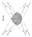
- Figure lOb shows very schematically the initial voxel space VS' where the camera arrangement comprises four cameras A' to D' arranged above and looking down on the object and four cameras A" to D" arranged below and looking up at the object with, as in the example described above, the cameras being spaced at 90° intervals around the object.
- the periphery of the voxel space VS itself is, of course, determined by the boundary of the volume VB and the size of the voxels relative to the size of the bound volume VB.
- the size of the voxels, and thus the resolution to which the 3D object surface can be generated will depend upon the available computational capacity of the CPU 22 and the time available for the computation of the 3D object surface.
- the voxel space VS may consist of 100,000 voxels or up to several millions of voxels.
- the method described above of defining the initial voxel volume by the intersection of the viewing cones of the camera positions avoids the disadvantages discussed above of defining the initial voxel volume using the silhouette or boundary of the object whose surface is to be generated and should also reduce the number of computations required to achieve the final 3D object surface in contrast to arrangements where the initial voxel space is defined arbitrarily so as to be sufficiently large to enclose the 3D object whose surface is to be generated.
- Figure 12 shows a top level flow chart for this method.
- the CPU 22 performs a test procedure for a first one of the surface voxels n of the initial voxel space VS to determine whether it should be removed, retained or sub-divided and then performs further processing in accordance with that determination so that the voxel is removed, retained or sub-divided and the sub-voxels subjected to further processing as will be described below.
- step S22 the CPU 22 repeats the test procedure of step S21 for the remaining surface voxels until each of the surface voxels of the initial voxel space has been processed in accordance with step S21.
- the CPU 22 determines at step S23 whether any voxel or sub-voxel has been removed and, if the answer is yes, resets its counters at step S24 so as to enable steps S21 and S22 to be repeated for the remaining voxels. Steps S21 and S22 are repeated until the answer at step S23 is no.
- the reason for repeating the voxel sweep effected by steps S21 and S22 when voxels have been removed is that the removal of a voxel or sub-voxel may cause voxels that were previously completely occluded by other voxels or sub-voxels to become non-occluded or partially non-occluded at least for some images and may also cause voxels or sub-voxels that were previously hidden by other voxels or sub-voxels from certain of the images to be projectable into those images.
- the removal of a voxel or sub-voxel may effect the photoconsistency of the remaining voxels and sub-voxels.
- each surface voxel is checked against each image in each voxel sweep.
- the images in which a voxel is visible will, however, be at least partly determined by the geometric arrangement of the camera positions at which the images were recorded. It thus should be possible to determine from these camera positions that certain surface voxels will not be visible or will not be visible in sufficient images to enable their photoconsistency to be checked. Where this can be determined, then the voxel colouring process may be repeated for another set of camera positions, if available, to enable the photoconsistency of those surface voxels to be checked.
- the CPU 22 will determine whether there is another set of camera positions that should be considered. When the answer at step S25 is yes, then the CPU 22 will repeat at step S26 steps S21 to 25 for the next set of camera positions until all sets of camera positions have been considered.
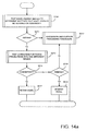
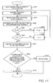
- Figure 14a shows in greater detail the test procedure for a voxel carried out at step S21 in Figure 12.
- the CPU 22 tests the voxel against each of the images in turn to determine whether the voxel should be retained or sub-divided. The CPU 22 then checks at step S211 whether the result of the test at step S210 was that the voxel should be retained. If the answer is no, then at step S212 the CPU subjects the voxel to sub-division and further processing as will be described in detail below.
- step S211 If the answer at step S211 is yes, then the CPU 22 tests, at step S213, the consistency between projections of the same voxel into the different images and then checks at step S214 whether the result of the tests was that the images were consistent. When the answer at step S214 is yes, then the CPU 22 retains the voxel at step S217.
- step S214 If the answer at step S214 is no, then the CPU 22 checks at step S216 whether the result of the test at step S213 was that the voxel should be removed and if so removes the voxel at step S217. If the answer at step S216 is no then the CPU 22 carries out step S212 as described above so that the voxel is subjected to sub-division on further processing.
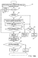
- Figure 14b shows step S210 in greater detail.
- the CPU 22 tests to see whether a surface voxel (1) projects into an image; (2) is occluded in respect of that image; or (3) is partially occluded with respect to that image and should be sub-divided.
- the CPU 22 then checks at step S41 whether the answer at step S40 was that the voxel was occluded with respect to that image and. If so, the CPU 22 ignores that image for that voxel at step S42 and determines that, on the basis of that image, the voxel should be retained at S50. If, however, the answer at step S41 is no, then the CPU 22 checks to see whether the answer at step S40 was that the voxel was partially occluded with respect to that image (step S43).
- step S43 the CPU 22 checks at step S44 whether the current voxel size is the minimum allowable and if the answer is yes decides at step S45 that that image should be ignored for that voxel and that, on the basis of the image, the voxel should be retained. If the answer at step S44 is no, then the CPU 22 determines at step S46 that the voxel should be sub-divided.
- step S47 the CPU projects each of the eight corners of the voxel under test into the image to identify the pixel patch corresponding to that voxel.
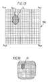
- Figure 13 shows schematically an array of pixels P o , o to P n , n of part of an image IM c to illustrate the projection of a voxel to a pixel patch Q (shown as a hatched area).
- the CPU 22 determines at step S48 the colour of that pixel patch (for example Q in Figure 13). Where, as shown in Figure 13, the boundary of the pixel patch cuts through pixels (such as pixel P 6 , 4 in Figure 13) the entirety of these pixels is considered to fall within the pixel patch.
- the CPU 22 determines the colour of the pixel patch by summing the respective numbers (each between zero and 255 for each colour in this example) associated in its memory with the different pixels forming the patch and dividing that sum by the number of pixels in the pixel patch to determine the colour (where all the pixels are the same colour) or the average colour of the pixel patch. This colour is then stored in the memory 22a by the CPU 22 for that voxel and that image m.
- the CPU 22 then checks at step S49 whether the variance of the colours of the pixels in the patch exceeds a predetermined threshold, for example whether the standard deviation in colour is greater than 10. If the answer is yes, then the CPU 22 determines that that image contains too much colour variation and that that image cannot be used for checking the photoconsistency of that voxel without sub-division of the voxel. The CPU 22 then determines at step S44 whether the voxel size is already at a minimum. If the answer is yes, the CPU 22 determines at step S45 that that image should be ignored for the voxel and that the voxel should, as far as that image is concerned, be retained at step S50. If the answer is no, then the CPU determines at step S46 that the voxel should be sub-divided.
- a predetermined threshold for example whether the standard deviation in colour is greater than 10.
- step S51 in Figure 14b the CPU 22 repeats steps S40 to S50 for each of the available images and, at step S52 checks to see whether a decision was taken at step S46 to sub-divide the voxel with respect to any one or more of the images. If the answer at step S52 is yes, then the CPU 22 confirms at step S53 that the voxel is to be sub-divided. If, however, the answer at step S52 is no, then the CPU 22 determines at step S54 that the voxel should be retained.
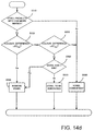
- Figure 14c shows in greater detail the steps carried out at step S40 in Figure 14b.
- the CPU 22 defines a straight line passing through the centre of the voxel and the focal point F of the camera position which produced the image for which the voxel is being tested.
- Figure 10a shows a voxel V x being projected into the image IM c along the line xx.
- the CPU 22 then checks at step S402 whether any other voxels lie on the line between the voxel under test and the focal point F. If the answer is no, then the CPU 22 determines that the voxel is not occluded for that image at step S403. If, however, the answer at step S402 if yes, then the CPU 22 checks the information in its memory 22a to determine, at step S404, whether the voxel lying on the line between the voxel being tested and the focal point F is a voxel that has been sub-divided, that is, as will be described below whether the information in the CPU's memory 22a includes information marking the voxel on the line as being partially full.
- step S404 determines at step S406 that the voxel under test is partially occluded for that image. If the answer at step S404 is no, then the CPU 22 determines that the voxel under test is completely occluded for that image at step S405. The information as to whether the voxel under test is occluded, partially occluded or not occluded in that image is stored in the memory 22a.
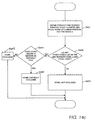
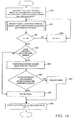
- Figure 14d shows in greater detail step S213 of Figure 14A.
- the CPU 22 checks to see whether the voxel under test projects into two or more images. If the answer is no, the CPU 22 determines that the consistency of the voxel cannot be checked and assumes that the voxel is consistent at step S520. If, however, the answer is yes, then at step S530 the CPU 22 compares the colour values of the pixel patches Q for each of the images in which the voxel was visible and determines whether the colour difference between the patches is greater than or equal to a first predetermined threshold ⁇ C TH1 by determining whether the standard deviation of the colour values exceeds a first predetermined value. Typically, the predetermined value for the standard deviation may be 20.
- any technique may be used to determine the standard deviation. If the colour difference between the patches exceeds ⁇ C TH1, then the CPU 22 determines at step S540 that the voxel is inconsistent and removes it at step S540. If, however, the answer at step S530 is no, then the CPU 22 checks at step S540 whether the colour difference is less than or equal to a second predetermined threshold ⁇ C TH2 smaller than the first predetermined threshold. In this example the second predetermined threshold is a standard deviation of 10. If the answer at step S550 is yes the standard deviation is equal to or smaller than the second predetermined threshold then the CPU 22 determines at step S520 that the voxel is consistent and should be retained.
- step S550 the CPU 22 checks at step S560 whether the voxel size is already at a minimum and, if so, decides that the voxel should be removed at step S540. Otherwise the CPU 22 determines that the voxel should be sub-divided (step S570). Thus, if the pixel patches into which the voxel projects have a colour variation greater than or equal to the first threshold the CPU 22 determines that that voxel cannot possibly form part of the 3D object surface because its colour is too inconsistent between images.
- the CPU 22 determines that the photoconsistency check is not conclusive and that the voxel should be sub-divided as part of the voxel may form part of the surface.
- FIG 15 shows a flow chart illustrating in greater detail the processing carried out step S212 in Figure 14A.
- the CPU 22 adds to its memory 22a information marking the original voxel as partially full and retains that voxel to enable the testing described above with reference to Figure 12 to be carried out for subsequent voxels.
- the CPU 22 sub-divides the voxel into a set of subsidiary voxels, sub-voxels.
- Figure 11 shows a voxel V x that has been divided into eight subsidiary voxels of which sub-voxels V1 to V6 are visible in Figure 11. It will, however, be appreciated that the CPU 22 may, for example, divide the voxel into 16 or more sub-voxels.
- the CPU 22 performs the test procedure described above with reference to step S21 in Figure 12 for a first one of the sub-voxels to determine whether it should be removed, retained or sub-divided at step S262 and then, at step S263, repeats that test procedure for each of the other sub-voxels of that voxel.
- the test procedure at step S262 is carried out in the manner described above with reference to Figures 12 to 14d with the exception that, of course, it is a sub-voxel rather than a voxel that is being tested.
- Figure 16 shows diagrammatically a portion of the part of the part of the image shown in Figure 13 to illustrate the projection of a sub-voxel into a pixel patch QS in an image.
- a sub-voxel is found to be partially occluded (that is a correspondingly sized sub-voxel which has already been divided into further subsidiary voxels is on the line between that sub-voxel and the focal point for the image concerned,) or the colour variance of the patch into which the sub-voxel projects in an image exceeds the predetermined threshold or the colours of the patches into which the sub-voxel projects are inconsistent, then that sub-voxel may itself be sub-divided.
- the CPU 22 checks at step S44 in Figure 14b or step S56 in Figure 14d whether the minimum voxel size has been reached and if so determines that the minimum size sub-voxel should be removed rather than sub-divided.
- the minimum size may be determined in dependence on the resolution of the images being considered and may, for example, be the size of a sub-voxel that projects to a single pixel in an image.
- the CPU 22 determines that a voxel (for example voxel V X in Figure 11) is partially occluded, projects to a pixel patch having too large a colour variance or the colour difference between the pixel patches is too great, the CPU 22 does not immediately remove that voxel but rather sub-divides that voxel into subsidiary voxels (eight in the example given above) and then tests each of those sub-voxels in turn in the same way as the voxels were tested.
- a voxel for example voxel V X in Figure 11
- any consistent sub-voxels are retained whereas, if a sub-voxel is determined to be photo-inconsistent, the CPU 22 checks whether the minimum sub-voxel size has been reached and, if so, removes the sub-voxel. If not, the CPU 22 further sub-divides the sub-voxel and repeats the photoconsistency check for each further sub-divided voxel.
- the CPU 22 performs step S21 in Figure 12 by first checking whether a voxel is occluded, partially occluded or unoccluded (step S14 in Figure 14b) and, if the voxel is unoccluded, goes on to check the colour variance (step S49 in Figure 14b). These two tests could, however, be combined so that, for example, the CPU 22 checks to see if the voxel is fully occluded and, if not, then checks the colour variance (step S49 in Figure 14b) and, if the colour variance does not exceed the predetermined threshold, only then checks to see if the voxel is partially occluded.
- the photoconsistency check described with reference to Figure 14d may be combined with these other checks so that, for example, the CPU 22 checks first to see if the voxel is visible in at least two of the images then carries out the photoconsistency check and then carries out the colour variance test (step S49 in Figure 14b) and the partial-occlusion test only if the photoconsistency test is satisfactory.
- the partial-occlusion test may be carried out before the photoconsistency test.
- step S53 of Figure 14d could be omitted so that the CPU 22 only tests to see if the colour difference is less than or equal to the second predetermined threshold and, if the answer is no, sub-divides the voxel if it has not already reached the minimum size.
- first and second predetermined thresholds may be user adjustable so as to enable a user to adjust these thresholds in accordance with the 3D object whose surface is being generated.
- the colour variance threshold may similarly be adjusted.
- the method described with reference to Figures 12 to 15 thus enables the process of determining the photoconsistency of a voxel to be further refined by, when it is not clear whether a voxel forms part of the 3D object surface, sub-dividing that voxel into subsidiary voxels (sub-voxels) and then testing the sub-voxels for consistency with the 3D object surface.
- a voxel can be sub-divided and the sub-voxels tested before making any decision to remove that voxel means that it is not necessary for the initial size of the voxels to be determined by the smallest colour area in the 3D object surface to be generated. Rather, the initial voxel size can be, for example, determined by the overall colouring of the images being used and need only be made smaller (sub-divided) where required, that is where the images have rapidly changing areas of colour such as may, for example occur at edges or highly patterned areas of the surface.
- the voxel colouring process avoids or reduces the possibility of erroneous removal of a voxel due to significant colour changes within the colour patches into which that voxel projects without having to define the initial size of the voxels as being equivalent to the minimum single colour area in the images. This therefore should reduce the computational power and time required to generate the 3D object surface.
- a sub-voxel has the same shape as the voxels and the photo inconsistency threshold is the same for the voxels as it is for sub-voxels. This need not, however, necessarily be the case and there may be advantages to having sub-voxels of different shape from the voxels and to using different photo inconsistency thresholds for voxels and sub-voxels.
- Figure 17 shows a flowchart illustrating another example of a subdivision and further processing procedure that may be carried out at step S212 in Figure 14a.
- steps S260 and S261 are carried out as for the additional processing shown in Figure 15.
- a first sub-voxel i is projected into a pixel patch in a first image m (for example the pixel patch QS in Figure 16) at step S264 in Figure 17 by projecting each corner of the sub-voxel into the image along the line passing through that corner and the focal point of the image.
- the CPU 22 increments M by 1 at step S267 and repeats steps S264 to S266 until the answer at step S266 is yes).
- step S271 When the answer at step S271 is yes, the CPU 22 will have determined and stored for each sub-voxel the colour of the pixel patches associated with that sub-voxel. It will, of course, be appreciated that the order in which steps S261 to S267, S271 and S272 are carried out may be altered so that each sub-voxel is projected into an image and then the step of projecting the sub-voxels is repeated image by image.
- the CPU 22 compares at step S273 the determined colours of the pixel patches for the voxel being considered. Then, at step S274, the CPU 22 determines whether there is, for that voxel, a set of pixel patches consisting of a pixel patch for each image for which the colour difference is ⁇ C TH . Thus, the CPU 22 does not check whether there is photoconsistency between corresponding sub-voxels but rather whether there is photoconsistency between pixel patches from the different images regardless of which sub-voxel projects into that pixel patch. If the answer at step S274 is no there is no such set of pixel patches, then the CPU 22 removes the entire voxel at step S275. If, however, the answer at step S274 is yes, then the entire voxel is retained at step S276.
- Figure 18 illustrates another way of carrying out the voxel colouring process that replaces step S21 described above with reference to Figures 12 to 15.
- the CPU 22 allocates each pixel of each image to be used for the voxel colouring process to a quantum of a quantized colour space and stores a quantized colour map for each image.
- Any appropriate conventional colour space may be used.
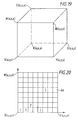
- the colour space is a cubic RGB colour space in which the origin (0,0,0) represents black (K) while the corners of the cube along the x, y and z axes represent red (R), green (G) and blue (B), respectively.
- the colour space shown in Figure 19 is quantized by dividing the colour cube into a set of smaller cubes.
- Figure 20 shows one plane of the colour cube to illustrate this division.
- each side of the colour cube is divided by eight so that the colour space is divided into 512 quanta.
- Figure 20 shows the quanta QU as abutting one another and not overlapping.
- the quantized colour map is stored for each image so that, instead of being represented by the original RGB value, each pixel is represented by a number identifying the corresponding quantum.
- the CPU projects voxel n into a pixel patch in image m and stores a quantized colour map for the patch. This is carried out in the manner shown in Figure 14c except that the CPU 22 tests only to see whether the voxel is fully occluded or unoccluded, that is steps S404 and S406 of Figure 14c are omitted.
- This quantized colour map will indicate the frequency of occurrence of each colour quantum in that pixel patch.
- the quantized colour map may be compressed for a particular pixel patch so that only the portion of the colour space containing quanta present in that pixel patch is stored.
- the quantized colour map may be stored in tabular form as shown in Figure 20 with each quantum indicating whether, and if so how many times, a colour quantum appears in a pixel patch.
- Figure 20 shows some of the colour quanta associated with numbers indicating the frequency of occurrence of those quanta in a pixel patch.
- the quantized colour map may be stored as a histogram.
- the CPU 22 determines if the voxel projects into two or more images (step S64). If the answer is no, the CPU determines that the photoconsistency cannot be checked and retains the voxel at step S65.
- the CPU 22 compares, at step S66, the quantized colour maps for the pixel patches for the images into which the voxel projects. The CPU 22 then determines at step S67 whether the quantized colour maps share at least one quantized colour.
- Step S68 determines that the voxel is photo-inconsistent and removes it at step S68. If, however, the answer is yes, then the CPU retains that voxel at step S65. Steps S22 to S26 are then carried out as described above with reference to Figure 12 at step S69.
- the methods described above with reference to Figures 15, 17 and 18 enable the voxel colouring process to take account of voxels that project to occluding boundaries or to areas of high spatial frequency so that the voxel does not project to an area of constant colour.
- the method described with reference to Figure 15 enables such voxels to be sub-divided and the individual sub-voxels to be checked while the methods described above with reference to Figures 17 and 18 err on the side of caution so that if there is at least some correspondence in colour between parts of the different pixel patches associated with a voxel, that voxel is retained.
- the CPU 22 selects a first set of images for use in the voxel colouring process.
- This first set of images will consist of a sub-set of the images used to determine the initial voxel space.
- the first set of images will consist of up to 20 to 30 images taken at different positions and orientations around the object.
- the CPU 22 performs a voxel colouring process using the first set of images as described above with reference to Figures 12a and 12b or Figures 12a and 12b as modified by Figure 15 or 17, or Figure 18.
- the CPU 22 stores at step S302 the current voxel space together with the determined colour for each photoconsistent non-occluded voxel of the current colour space.
- the CPU 22 selects another image from the stored images, that is an image not in the first set of images, and at step S301a the CPU 22 performs the voxel colouring process using the current voxel space and the new image as will be described in greater detail below with reference to Figures 22a and 22b.
- the CPU determines whether the voxel colouring process converged to a reasonable 3D object surface.
- This determination may be effected by the CPU 22 causing the 3D object surface to be displayed to the user on the display 24 together with a message saying "Please confirm acceptance of the 3D object surface" so that the user can determine whether the voxel colouring process has proceeded satisfactorily or whether erroneous removal of voxels has resulted in an erroneous 3D object surface.
- the CPU 22 itself may determine roughly whether the 3D object surface is acceptable by using the data regarding the volume of the object that may previously have been input by the user. In this case, the CPU 22 would determine that the 3D object surface is not acceptable if the volume bounded by that 3D object surface is less than the expected volume of the object.
- step S305 the CPU 22 increases the allowable colour difference used in the voxel colouring process and repeats steps S301a, S304 and S305 until the CPU determines at step S304 that the 3D object surface is acceptable.
- This repetition of the voxel colouring process is possible because the voxel space that resulted from the previous voxel colouring process is stored at step S302 and the image data for the'new image added for the current voxel colouring process is stored at step S303 and is not discarded until the answer at step S304 is yes.
- This method thus enables a user to return to the previously determined voxel space if the voxel colouring process carried out at step S301a results in erroneous removal of one or more voxels or even catastrophic failure of the voxel colouring process.
- the CPU 22 stores the newly derived voxel space as the current voxel space together with the determined colour for each photoconsistent non-occluded voxel and discards the previously stored image at step S306 and then checks at step S307 whether there is another image available.
- Step S307 may be carried out automatically by the CPU 22 where a large number of images have been pre-stored.
- the images may be selected by the CPU in any predetermined order.
- the images may be successive images along a predetermined path around the object.
- the first set of images may consist of images taken at predetermined intervals or angles relative to one another around the object and the next images may be intermediate those images and so on.
- the CPU 22 may allow the user a choice in the next image selected.
- the CPU 29 may display a message to the user requesting the user to select one of a number of additional pre-stored images and may also give the user the opportunity to input data for further images (for example via a removable disc 27, as a signal over the interface I or using a digital camera).
- the user can view the results of the previous voxel colouring process and determine whether it would improve the 3D object surface if data from one or more additional images was also used in the voxel colouring process.
- Steps S303 to S307 are repeated until the answer at step S307 is no, that is no more images are available.
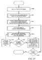
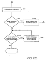
- Figures 22a and 22b illustrate in greater detail the step S301a of Figure 21 of performing a voxel colouring process using the current voxel space and a new image.
- the voxel n is projected into a pixel patch in the new image in the manner described above with reference to Figure 14. If the voxel n does not project into the new image then as described with reference to Figure 14, the CPU 22 proceeds to point C which is step S228 in Figure 22a and if all the non occluded voxels of the current voxel volume have not yet been projected into the new image, increments n by 1 at step S229 and then repeats step S221.
- the CPU 22 determines at step S223 the colour of the pixel patch and stores this colour in association with the voxel n for the new image in its memory 22a.
- the step S223 of determining the pixel patch colour is carried out in the same manner as described above with reference to Figure 12a.
- the CPU 22 compares the colour of the pixel patch for the new image with the stored colour associated with that voxel in the current voxel space.
- the CPU checks at step S225 whether the colour difference is less than or equal to the predetermined threshold ⁇ C TH . If the answer is no, the voxel is removed at step S226 while if the answer is yes the voxel is retained at step S227.
- the CPU determines at step S228 whether all the non-occluded voxels of the current voxel space have been visited and if the answer is no increments n by 1 at step S229 and then repeats steps S221 to S229 until the answer at step S228 is yes.
- the CPU 22 determines at step S230 that the voxel sweep has been completed (that is all non-occluded voxels have been visited). The CPU then checks at step S231 whether any voxels have been removed in the sweep and if the answer is yes resets n and m for the remaining voxels at step S232 and, for the reasons given above, repeats steps S221a to S232 until the answer at step S231 is no. When the answer at step S231 is no, the CPU 22 determines whether there are any other sets of camera positions to be considered at step S223 and if the answer is yes repeats at step S234 steps S221a to S234 until all of the sets of cameras have been considered.
- Figures 23, 24a and 24b illustrate another method for defining the 3D object surface once the initial voxel space has been defined.
- Figure 23 corresponds to Figure 21 while Figures 24a and 24b correspond to Figures 22a and 22b.
- the method shown in Figures 23, 24a and 24b differs from that described above with reference to Figures 21 to 22 in that, in this case, a number of previous images are retained in addition to the new image and the voxel colouring process is repeated using the current voxel space, the stored previous images and the new images.
- the number of previous images used will be considerably less than that used as the first set of images and may be, for example, 10.
- the number of previously stored images is kept constant so that, each time a new image is added, the oldest of the previously stored images is discarded. Where images of the first set still remain, then the image to be discarded (that is the "oldest" image) will be selected at random from that first set. Once all of the first set of images have been discarded, then the oldest image can be determined by looking at the time at which that image was added.
- steps S300 to S302 are carried out in the same manner as described above with reference to Figure 21.
- the CPU 22 stores the new image together with x (in this example 10) of the previously used images and discards all other images.
- Step S301b The voxel colouring process is then carried out at step S301b using the current voxel space and the new set of images (that is the new image and the previous 10 images). Steps S304 to S307 are then carried out as described above with reference to Figure 21.
- the voxel colouring process carried out at step S301 is the same as that described above with reference to Figures 12 and 14 or Figures 12a and 12b when modified by Figure 17 or 18 or Figure 18.
- the voxel colouring process carried out at step S301b differs somewhat from that described above with reference to Figures 22a and 22b as can be seen from Figures 24a and 24b.
- the CPU 22 projects voxel n into a pixel patch in a first one of the new set of images in the manner described above with reference to Figure 14.
- the CPU 22 determines and stores the colour of the pixel patch at step S222a in the manner described above and at step S223a the CPU 22 determines whether the voxel n has been projected into each of the new set of images. If the answer at step S223a is no, then the CPU 22 projects voxel n into the next one of the new set of images at step S223b in the manner described above with reference to Figure 14. When the answer at step S223a is yes, the CPU 22 determines at step S224a whether the voxel n projects into at least one of the new set of images.
- the CPU 22 determines that it is not possible to check the photoconsistency of that voxel in this particular voxel colouring process and so retains that voxel at step S227 ( Figure 24b). If the answer at step S224a is yes, then the CPU 22 compares, at step S224a, the colours of the pixel patches for the ones of the new set of images into which the voxel n projects and the colour associated with that voxel in the current voxel volume. The CPU 22 then determines at step S225 whether the difference in colour between the pixel patches and the colour associated with that voxel in the current voxel volume is less than or equal to ⁇ C TH .
- Step S225 If the answer at step S225 is no, then the voxel is removed at step S226 while if the answer is yes the voxel is retained at step S227. Steps S228 to S234 are then carried out as described above with reference to Figures 22a and 22b.
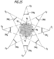
- Figure 25 shows a top plan view corresponding to Figure 8 but part way into a voxel colouring process (so that some voxels have already been removed) to illustrate the effect of adding camera positions.
- the initial camera positions A to D are represented in Figure 25 by the corresponding focal points F A to F D and the imaging areas IM A to IM D while additional camera positions E to H are represented in Figure 25 by the focal points F E to F H and the imaging areas IM E to IM H .
- voxel VA is visible at only one of the original four camera positions, that is camera position B, because intervening voxels occlude voxel VA as far as the other three camera positions A, C and D are concerned.
- voxel VX amongst others occludes voxel VA from camera position C.
- voxel VD is visible only at camera position B of the four original camera positions while voxel VB is visible at camera positions C and D and voxel VC is visible at camera position A.
- voxel VD when the additional camera positions are added, voxel VD also becomes visible at camera position E so that the voxel VD is visible from three camera positions which should enable a more accurate determination as to whether the voxel VD forms part of the 3D object surface or not.
- voxel VB which was visible at two of the original camera positions C and D becomes visible at four camera positions B, C, F and G when the four additional camera positions are added which should again enable greater accuracy in determining whether or not the voxel forms part of the 3D object surface.
- the additional camera positions are provided intermediate the original four camera positions.
- a further additional camera position may, for example, be provided looking directly down onto the top of the object.
- the manner in which additional camera positions are added may be determined by the CPU 22 in accordance with a pre-stored algorithm.
- each set of additional camera positions may add a camera position intermediate each pair of adjacent camera positions.
- the addition of camera positions may be under the control of the user so that, for example, at step S307 in Figures 21 and 23, the user determines the selection of the additional image (and thus the camera position) on the basis of the current estimate of the 3D object surface. This enables the user to add additional camera positions at the points where he can see from visual inspection of the estimated 3D object surface that further information is required so as to better define the 3D object surface.
- the likelihood of a voxel that is not actually on the surface of the 3D object being erroneously retained will reduce with increase in the number of images used.
- the methods described above enable further refinement of the generated 3D object surface so as to bring it into closer agreement with the actual 3D object surface without significantly increasing the amount of data that needs to be stored at any one time by the main processing unit.
- a single new image is added for each successive voxel colouring process.
- a set of new images may be added.
- images recorded at all or subsets of the additional camera positions shown in Figure 25a may be added simultaneously at step S303 in Figure 21 and step S303a in Figure 23 and the further voxel colouring processes of steps S301a and S301b carried out using all simultaneously added new images.
- the set of previous images may consist simply of the last used x images or may consist of images that are strategically important in the voxel colouring process. These images may be selected by the user.
- the CPU 22 may display to the user on display 25 a message requesting the user to select from the currently stored images the images to be retained for the next voxel colouring process.
- the initial voxel space defining process described above with reference to Figures 3 to 11 may be used with the voxel colouring process described with reference to Figures 12a and 12b, or Figures 12a and 12b as modified by Figure 17 or Figure 18 or the voxel colouring process as described above with reference to Figures 18 and 12b or any conventional voxel colouring process.
- the iterative voxel colouring processes described above with reference to Figures 21 to 22a or 23 to 24 may be used in combination with the modifications described above with reference to Figures 15, 17 and 18.
- the voxel colouring processes described above with reference to Figures 12a, 12b and 15, Figures 12a, 12b and 17 or Figures 18 and 12b may be used where the initial voxel space is defined in the manner described in the aforementioned University of Rochester Computer Sciences Technical Report or any other conventional process for defining the initial voxel space, for example by setting the initial voxel space as a volume known by a user to be sufficiently large to encompass the object whose 3D surface is to be generated.
- the iterative voxel colouring processes described above with reference to Figures 21 to 22b or Figures 23 to 24 may be used with such known initial voxel space defining techniques.
- the initial voxel space or resulting 3D object surface data may be downloaded onto a storage medium such as a disc or supplied as a signal over, for example, a network.
- the texture data generation module 14 shown in Figure 1 may be used to generate texture data from the input image data showing the object for rendering the 3D object surface produced as described above.
- the texture data generation module may form part of the same image processing apparatus or may be provided by a separate image processing apparatus to which the 3D object surface data is downloaded from a storage medium or supplied as a signal. It will, of course, be appreciated that the focal length of a camera may be so long that, in practice, the viewing cone of the camera can be represented by a viewing volume in which the rays defining the viewing volume are parallel or substantially parallel to one another.
- This process described below calculates corner points, to sub-pixel accuracy, from a single grey scale or colour image. It does this by first detecting edge boundaries in the image and then choosing corner points to be points where a strong edge changes direction rapidly.
- the method is based on the facet model of comer detection, described in Haralick and Shapiro i .
- the algorithm has four stages:
- the comer detection method works on grey scale images.
- edge strengths and directions are calculated using the 7 ⁇ 7 integrated directional derivative gradient operator discussed in section 8.9 of Haralick and Shapiro i .
- the row and column forms of the derivative operator are both applied to each pixel in the grey scale image.
- the results are combined in the standard way to calculate the edge strength and edge direction at each pixel.
- the output of this part of the algorithm is a complete derivative image.
- the edge boundaries are calculated by using a zero crossing edge detection method based on a set of 5 ⁇ 5 kernels describing a bivariate cubic fit to the neighbourhood of each pixel.
- the edge boundary detection method places an edge at all pixels which are close to a negatively sloped zero crossing of the second directional derivative taken in the direction of the gradient, where the derivatives are defined using the bivariate cubic fit to the grey level surface.
- the subpixel location of the zero crossing is also stored along with the pixel location.
- edge boundary detection is described in more detail in section 8.8.4 of Haralick and Shapiro i .
- the corner points are calculated using a method which uses the edge boundaries calculated in the previous step.
- Corners are associated with two conditions:
- Each of the pixels on the edge boundary is tested for "cornerness” by considering two points equidistant to it along the tangent direction. If the change in the edge direction is greater than a given threshold then the point is labelled as a corner. This step is described in section 8.10.1 of Haralick and Shapiro'.
- the corners are sorted on the product of the edge strength magnitude and the change of edge direction.
- the top 200 comers which are separated by at least 5 pixels are output.
- This process described below tracks feature points (typically corners) across a sequence of grey scale or colour images.
- the tracking method uses a constant image velocity Kalman filter to predict the motion of the corners, and a correlation based matcher to make the measurements of corner correspondences.
- the method assumes that the motion of comers is smooth enough across the sequence of input images that a constant velocity Kalman filter is useful, and that corner measurements and motion can be modelled by gaussians.
- transition matrix and process covariance matrix are constant and have the following values:
- the correlation score between a window around the previously measured comer and each of the pixels in the range gate is calculated.
- the two top correlation scores are kept.
- the pixel with the top correlation score is kept as the latest measurement.
- G KH T ( HKH T + R ) -1 X ⁇ X + G ( X - HX ) K ⁇ ( I-GH ) K
- G the Kalman gain
- H the measurement matrix
- R the measurement covariance matrix
- the parameters of the algorithm are:
- ⁇ 0 2 200(pixels/frame) 2 .
- the process velocity variance is set to the fixed value of 50 (pixels/frame) 2 .
- the process velocity variance would have to be increased above this for a hand-held sequence. In fact it is straightforward to obtain a reasonable value for the process velocity variance adaptively.
- This model takes into account, in a heuristic way, the fact that it is more likely that an outlier will be obtained if the range gate is large.
- the measurement variance (in fact the full measurement covariance matrix R) could also be obtained from the behaviour of the auto-correlation in the neighbourhood of the measurement. However this would not take into account the likelihood of obtaining an outlier.
- the method consists of five processes, which are run consecutively:
- the aim of this process is to segment an object (in front of a reasonably homogeneous coloured background) in an image using colour information.
- the resulting binary image is used in voxel carving.
- the algorithm has two stages:
- each colour field is used. This function is chosen to try and spread out the data into the available bins. Ideally each bin in the hash table has a small number of colour entries. Each quantised colour RGB triple is only added once to the table (the frequency of a value is irrelevant).
- Step 2) Segment each image
- Post processing for both methods a post process is performed to fill small holes and remove small isolated regions.
- a median filter is used with a circular window. (A circular window is chosen to avoid biasing the result in the x or y directions.)
- the aim ofthis process is to produce a 3D voxel grid, enclosing the object, with each of the voxels marked as either object or empty space.
- the input to the algorithm is:
- a pre-processing step calculates a suitable size for the voxels (they are cubes) and the 3D locations of the voxels, using "n", (xmin, ymin, zmin) and (xmax, ymax, zmax).
- the mid-point of the voxel cube is projected into each of the segmentation images. If the projected point falls onto a pixel which is marked as background, on any of the images, then the corresponding voxel is marked as empty space, otherwise it is marked as belonging to the object.
- Voxel carving is described further in "Rapid Octree Construction from Image Sequences" by R. Szeliski in CVGIP: Image Understanding, Volume 58, Number 1, July 1993, pages 23-32.
- the aim of the process is to produce a surface triangulation from a set of samples of an implicit function representing the surface (for instance a signed distance function).
- an implicit function representing the surface (for instance a signed distance function).
- the implicit function takes the value -1 for samples which are inside the object and +1 for samples which are outside the object.
- Marching cubes is an algorithm that takes a set of samples of an implicit surface (e.g. a signed distance function) sampled at regular intervals on a voxel grid, and extracts a triangulated surface mesh.
- Lorensen and Cline iii and Bloomentahl iv give details on the algorithm and its implementation.
- the signed distance allows the marching-cubes algorithm to interpolate the location of the surface with higher accuracy than the resolution of the volume grid.
- the marching cubes algorithm can be used as a continuation method (i.e. it finds an initial surface point and extends the surface from this point).
- the aim of the process is to reduce the number of triangles in the model, making the model more compact and therefore easier to load and render in real time.
- the process reads in a triangular mesh and then randomly removes each vertex to see if the vertex contributes to the shape of the surface or not. (i.e. if the hole is filled, is the vertex a "long" way from the filled hole). Vertices which do not contribute to the shape are kept out of the triangulation. This results in fewer vertices (and hence triangles) in the final model.
- the process therefore combines adjacent triangles in the model produced by the marching cubes algorithm, if this can be done without introducing large errors into the model.
- the selection of the vertices is carried out in a random order in order to avoid the effect of gradually eroding a large part of the surface by consecutively removing neighbouring vertices.
- the aim of the process is to texture each surface polygon (typically a triangle) with the most appropriate image texture.
- the output of the process is a VRML model of the surface, complete with texture co-ordinates.
- the triangle having the largest projected area is a good triangle to use for texturing, as it is the triangle for which the texture will appear at highest resolution.
- the image "i" is found such that the triangle is the most front facing (i.e. having the greatest value for n and t •v and i , where n and t is the triangle normal and v and i is the viewing direction for the "i"th camera).
- the vertices of the projected triangle are then used as texture co-ordinates in the resulting VRML model.
- This technique can fail where there is a substantial amount of self-occlusion, or several objects occluding each other. This is because the technique does not take into account the fact that the object may occlude the selected triangle. However, in practice this does not appear to be much of a problem.
Landscapes
- Engineering & Computer Science (AREA)
- Physics & Mathematics (AREA)
- General Physics & Mathematics (AREA)
- Theoretical Computer Science (AREA)
- Geometry (AREA)
- Computer Graphics (AREA)
- Computer Vision & Pattern Recognition (AREA)
- Software Systems (AREA)
- Image Generation (AREA)
- Image Processing (AREA)
- Image Analysis (AREA)
- Length Measuring Devices By Optical Means (AREA)
Applications Claiming Priority (2)
| Application Number | Priority Date | Filing Date | Title |
|---|---|---|---|
| GB9929957 | 1999-12-17 | ||
| GBGB9929957.0A GB9929957D0 (en) | 1999-12-17 | 1999-12-17 | Image processing apparatus |
Publications (2)
| Publication Number | Publication Date |
|---|---|
| EP1109131A2 true EP1109131A2 (de) | 2001-06-20 |
| EP1109131A3 EP1109131A3 (de) | 2003-10-01 |
Family
ID=10866587
Family Applications (1)
| Application Number | Title | Priority Date | Filing Date |
|---|---|---|---|
| EP00310509A Withdrawn EP1109131A3 (de) | 1999-12-17 | 2000-11-27 | Bildverarbeitungsgerät |
Country Status (3)
| Country | Link |
|---|---|
| EP (1) | EP1109131A3 (de) |
| JP (1) | JP2001236522A (de) |
| GB (1) | GB9929957D0 (de) |
Cited By (2)
| Publication number | Priority date | Publication date | Assignee | Title |
|---|---|---|---|---|
| CN105203052A (zh) * | 2015-11-12 | 2015-12-30 | 中航工业哈尔滨轴承有限公司 | 非接触式复合专用轴承测试仪 |
| CN118505166A (zh) * | 2024-07-16 | 2024-08-16 | 国网安徽省电力有限公司信息通信分公司 | 基于图像分析的输电线路无计划作业核查方法及系统 |
Families Citing this family (16)
| Publication number | Priority date | Publication date | Assignee | Title |
|---|---|---|---|---|
| JP3967626B2 (ja) * | 2002-04-30 | 2007-08-29 | 独立行政法人科学技術振興機構 | 画像データ圧縮処理方法および画像処理装置 |
| DE112006003361T5 (de) * | 2005-12-16 | 2008-10-16 | Ihi Corporation | Verfahren und Vorrichtung für das Aufzeichnen/Anzeigen von dreidimensionalen Formdaten und Verfahren und Vorrichtung für das Messen einer dreidimensionalen Form |
| CN101331379B (zh) | 2005-12-16 | 2012-04-11 | 株式会社Ihi | 自身位置辨认方法和装置以及三维形状的计测方法和装置 |
| CN101331381B (zh) | 2005-12-16 | 2011-08-24 | 株式会社Ihi | 三维形状数据的位置对准方法和装置 |
| JP4839237B2 (ja) * | 2007-02-07 | 2011-12-21 | 日本電信電話株式会社 | 3次元形状復元方法,3次元形状復元装置,その方法を実装した3次元形状復元プログラム及びそのプログラムを記録した記録媒体 |
| JP4732392B2 (ja) * | 2007-03-30 | 2011-07-27 | 日本電信電話株式会社 | 3次元形状データ生成方法 |
| JP5380792B2 (ja) * | 2007-06-15 | 2014-01-08 | 株式会社Ihi | 物体認識方法および装置 |
| CN101546424B (zh) * | 2008-03-24 | 2012-07-25 | 富士通株式会社 | 图像处理方法和装置及水印检测系统 |
| JP5218034B2 (ja) * | 2008-12-26 | 2013-06-26 | Kddi株式会社 | マスク画像を抽出する方法及びプログラム並びにボクセルデータを構築する方法及びプログラム |
| WO2016158855A1 (ja) * | 2015-03-31 | 2016-10-06 | 株式会社ニコン | 撮像システム、撮像装置、撮像方法、及び撮像プログラム |
| JP6736422B2 (ja) * | 2016-08-23 | 2020-08-05 | キヤノン株式会社 | 画像処理装置、画像処理の方法およびプログラム |
| JP6901885B2 (ja) * | 2017-03-24 | 2021-07-14 | Kddi株式会社 | 前景抽出装置及びプログラム |
| KR101866363B1 (ko) * | 2017-11-24 | 2018-06-12 | 공간정보기술 주식회사 | 사용자 기반 조건에 따른 3차원(3d) 모델링 생성과 제공 시스템 |
| WO2019126680A1 (en) * | 2017-12-22 | 2019-06-27 | Magic Leap, Inc. | Method of occlusion rendering using raycast and live depth |
| KR102030594B1 (ko) * | 2018-01-31 | 2019-11-08 | 가이아쓰리디 주식회사 | 3차원 지리 정보 시스템 웹 서비스를 제공하는 방법 |
| CN110992466B (zh) * | 2019-12-05 | 2021-05-18 | 腾讯科技(深圳)有限公司 | 光照探针生成方法、装置、存储介质和计算机设备 |
-
1999
- 1999-12-17 GB GBGB9929957.0A patent/GB9929957D0/en not_active Ceased
-
2000
- 2000-11-27 EP EP00310509A patent/EP1109131A3/de not_active Withdrawn
- 2000-12-18 JP JP2000384446A patent/JP2001236522A/ja not_active Withdrawn
Non-Patent Citations (4)
| Title |
|---|
| CONNOLLY C I ET AL: "3D scene reconstruction from multiple intensity images" INTERPRETATION OF 3D SCENES, 1989. PROCEEDINGS., WORKSHOP ON AUSTIN, TX, USA 27-29 NOV. 1989, LOS ALAMITOS, CA, USA,IEEE COMPUT. SOC, US, 27 November 1989 (1989-11-27), pages 124-130, XP010017917 ISBN: 0-8186-2007-2 * |
| EISERT P ET AL: "Multi-hypothesis, volumetric reconstruction of 3-D objects from multiple calibrated camera views" ACOUSTICS, SPEECH, AND SIGNAL PROCESSING, 1999. PROCEEDINGS., 1999 IEEE INTERNATIONAL CONFERENCE ON PHOENIX, AZ, USA 15-19 MARCH 1999, PISCATAWAY, NJ, USA,IEEE, US, 15 March 1999 (1999-03-15), pages 3509-3512, XP010328059 ISBN: 0-7803-5041-3 * |
| SEITZ S M ET AL: "PHOTOREALISTIC SCENE RECONSTRUCTION BY VOXEL COLORING" INTERNATIONAL JOURNAL OF COMPUTER VISION, KLUWER ACADEMIC PUBLISHERS, NORWELL, US, vol. 35, no. 2, 1999, pages 151-173, XP001024774 ISSN: 0920-5691 * |
| SZELISKI R: "RAPID OCTREE CONSTRUCTION FROM IMAGE SEQUENCES" CVGIP IMAGE UNDERSTANDING, ACADEMIC PRESS, DULUTH, MA, US, vol. 58, no. 1, July 1993 (1993-07), pages 23-32, XP000382074 ISSN: 1049-9660 * |
Cited By (2)
| Publication number | Priority date | Publication date | Assignee | Title |
|---|---|---|---|---|
| CN105203052A (zh) * | 2015-11-12 | 2015-12-30 | 中航工业哈尔滨轴承有限公司 | 非接触式复合专用轴承测试仪 |
| CN118505166A (zh) * | 2024-07-16 | 2024-08-16 | 国网安徽省电力有限公司信息通信分公司 | 基于图像分析的输电线路无计划作业核查方法及系统 |
Also Published As
| Publication number | Publication date |
|---|---|
| GB9929957D0 (en) | 2000-02-09 |
| EP1109131A3 (de) | 2003-10-01 |
| JP2001236522A (ja) | 2001-08-31 |
Similar Documents
| Publication | Publication Date | Title |
|---|---|---|
| US6990228B1 (en) | Image processing apparatus | |
| US6970591B1 (en) | Image processing apparatus | |
| US6975755B1 (en) | Image processing method and apparatus | |
| EP1109131A2 (de) | Bildverarbeitungsgerät | |
| US7508977B2 (en) | Image processing apparatus | |
| US6504569B1 (en) | 2-D extended image generation from 3-D data extracted from a video sequence | |
| US7272264B2 (en) | System and method for hole filling in 3D models | |
| US10477178B2 (en) | High-speed and tunable scene reconstruction systems and methods using stereo imagery | |
| EP3367334B1 (de) | Tiefenschätzverfahren und tiefenschätzvorrichtung für mehrfachansichtsbilder | |
| EP1059611A1 (de) | Bildverarbeitungsvorrichtung | |
| US20100284607A1 (en) | Method and system for generating a 3d model from images | |
| KR20090052889A (ko) | 이미지들로부터 깊이 맵을 결정하기 위한 방법 및 깊이 맵을 결정하기 위한 디바이스 | |
| EP1063614A2 (de) | Gerät zum Verwenden mehrere Gesichtsbilder aus verschiedenen Blickpunkten um ein Gesichtsbild aus einem neuen Blickpunkt zu erzeugen, dessen Verfahren, Gerät und Speichermedium | |
| EP1445736B1 (de) | Verfahren und System zur Bereitstellung einer Volumendarstellung eines dreidimensionalen Objektes | |
| EP3945495A1 (de) | Verfahren zur segmentierung eines objekts in einem bild | |
| GB2597238A (en) | A computer implemented method of generating a parametric structural design model | |
| CN118015197B (zh) | 一种实景三维逻辑单体化方法、装置及电子设备 | |
| EP1374181A1 (de) | Verfahren der bildverarbeitung zur fitness-schätzung eines 3d-maschenmodels das auf eine 3d-objektfläche abgebildet wird | |
| CN114943711A (zh) | 基于LiDAR点云和影像的建筑物提取方法和系统 | |
| Gao et al. | Indoor scene reconstruction from LiDAR point cloud based on roof extraction | |
| CN114549825B (zh) | 目标检测方法、装置、电子设备与存储介质 | |
| GB2362793A (en) | Image processing apparatus | |
| GB2365243A (en) | Creating a 3D model from a series of images | |
| GB2358307A (en) | Method of determining camera projections in 3D imaging having minimal error | |
| GB2358540A (en) | Selecting a feature in a camera image to be added to a model image |
Legal Events
| Date | Code | Title | Description |
|---|---|---|---|
| PUAI | Public reference made under article 153(3) epc to a published international application that has entered the european phase |
Free format text: ORIGINAL CODE: 0009012 |
|
| AK | Designated contracting states |
Kind code of ref document: A2 Designated state(s): AT BE CH CY DE DK ES FI FR GB GR IE IT LI LU MC NL PT SE TR |
|
| AX | Request for extension of the european patent |
Free format text: AL;LT;LV;MK;RO;SI |
|
| PUAL | Search report despatched |
Free format text: ORIGINAL CODE: 0009013 |
|
| AK | Designated contracting states |
Kind code of ref document: A3 Designated state(s): AT BE CH CY DE DK ES FI FR GB GR IE IT LI LU MC NL PT SE TR |
|
| AX | Request for extension of the european patent |
Extension state: AL LT LV MK RO SI |
|
| RIC1 | Information provided on ipc code assigned before grant |
Ipc: 7G 06T 7/00 B Ipc: 7G 06T 17/00 B Ipc: 7G 06T 15/20 A |
|
| 17P | Request for examination filed |
Effective date: 20040225 |
|
| AKX | Designation fees paid |
Designated state(s): DE FR GB IT NL |
|
| 17Q | First examination report despatched |
Effective date: 20071120 |
|
| STAA | Information on the status of an ep patent application or granted ep patent |
Free format text: STATUS: THE APPLICATION HAS BEEN WITHDRAWN |
|
| 18W | Application withdrawn |
Effective date: 20130326 |