EP1110325B1 - Verfahren und vorrichtung zur signalkompression im festpunktformat ohne bias - Google Patents
Verfahren und vorrichtung zur signalkompression im festpunktformat ohne bias Download PDFInfo
- Publication number
- EP1110325B1 EP1110325B1 EP99941157A EP99941157A EP1110325B1 EP 1110325 B1 EP1110325 B1 EP 1110325B1 EP 99941157 A EP99941157 A EP 99941157A EP 99941157 A EP99941157 A EP 99941157A EP 1110325 B1 EP1110325 B1 EP 1110325B1
- Authority
- EP
- European Patent Office
- Prior art keywords
- signal
- bit
- output
- bits
- input
- Prior art date
- Legal status (The legal status is an assumption and is not a legal conclusion. Google has not performed a legal analysis and makes no representation as to the accuracy of the status listed.)
- Expired - Lifetime
Links
Images


Classifications
-
- H—ELECTRICITY
- H03—ELECTRONIC CIRCUITRY
- H03M—CODING; DECODING; CODE CONVERSION IN GENERAL
- H03M7/00—Conversion of a code where information is represented by a given sequence or number of digits to a code where the same, similar or subset of information is represented by a different sequence or number of digits
- H03M7/30—Compression; Expansion; Suppression of unnecessary data, e.g. redundancy reduction
-
- G—PHYSICS
- G06—COMPUTING OR CALCULATING; COUNTING
- G06F—ELECTRIC DIGITAL DATA PROCESSING
- G06F7/00—Methods or arrangements for processing data by operating upon the order or content of the data handled
- G06F7/38—Methods or arrangements for performing computations using exclusively denominational number representation, e.g. using binary, ternary, decimal representation
- G06F7/48—Methods or arrangements for performing computations using exclusively denominational number representation, e.g. using binary, ternary, decimal representation using non-contact-making devices, e.g. tube, solid state device; using unspecified devices
- G06F7/499—Denomination or exception handling, e.g. rounding or overflow
- G06F7/49942—Significance control
- G06F7/49947—Rounding
- G06F7/49952—Sticky bit
-
- G—PHYSICS
- G06—COMPUTING OR CALCULATING; COUNTING
- G06F—ELECTRIC DIGITAL DATA PROCESSING
- G06F7/00—Methods or arrangements for processing data by operating upon the order or content of the data handled
- G06F7/38—Methods or arrangements for performing computations using exclusively denominational number representation, e.g. using binary, ternary, decimal representation
- G06F7/48—Methods or arrangements for performing computations using exclusively denominational number representation, e.g. using binary, ternary, decimal representation using non-contact-making devices, e.g. tube, solid state device; using unspecified devices
- G06F7/499—Denomination or exception handling, e.g. rounding or overflow
- G06F7/49942—Significance control
- G06F7/49947—Rounding
- G06F7/49963—Rounding to nearest
Definitions
- the present invention relates to signal compression. More particularly, the present invention relates to a novel and improved method and apparatus for compressing a fixed point signal without introducing a bias.
- Floating point notation has no fixed decimal point. Numbers are represented in floating point by two components: a mantissa and an exponent.
- Fixed point is a format in which all numerical quantities are expressed by a predetermined number of digits, with the decimal point implicitly located at some predetermined position. Fixed point numbers are the subject of the current invention.
- Different signals within a digital system may have different dynamic range requirements. For instance, multiplication of an M-bit number with an N-bit number results in a product having M+N bits for full precision. However, the system may not require that the product signal have that high a dynamic range. It may, therefore, be desirable to discard bits from the signal (i.e., compress the signal).
- Truncation refers to simply dropping one or more of the least significant bits or digits in this case from a signal. Truncation, however, introduces a negative bias into the compressed signal because truncation always involves throwing away a positive quantity (the truncated bits). These biases accumulate as more truncation operations are performed. This accumulated bias can significantly degrade downstream performance, particularly in low signal level environments. Rounding performs better than truncation, but nevertheless introduces a bias that also can degrade downstream performance.
- the present invention is a novel and improved method and apparatus for compressing fixed point signals without introducing a bias.
- signals are compressed according to a dithered rounding approach wherein signal values are rounded up and rounded down with approximately equal probability, canceling the bias that would otherwise result from the rounding operation.
- the present invention exploits numerical properties of the input signal in order to determine whether the signal value should be rounded up or down.
- An advantage provided by the current invention is that signal compression is achieved without the introduction of a bias. Signal compression may, therefore, be introduced at multiple points within a system without accumulating a signal bias and degrading downstream performance.
- a feature of the present invention is that one bit signal compression in general may be achieved in a particularly efficient fashion with a minimal amount of hardware.
- FIG. 1 depicts a signal compressor 106 that compresses an N-bit input signal 102 to an N-K bit output signal 104 (K-bit compression).
- K-bit compression in the present context refers to systematically reducing the number of bits used to represent a signal.
- signal compressor 106 reduces -the number of bits representing input signal 102 by K bits, thereby forming output signal 104.
- bit 1 refers to the least significant bit
- bit K refers to the K th least significant bit
- bit N refers to the most significant bit of an N-bit number.
- Groups of bits are also referred to as, e.g., the N-K most significant bits (identifying bit N-K through bit N of an N-bit number) or the K least significant bits (identifying bit 1 through bit K of a number having at least K bits).
- input signal 102 and output signal 104 will be referred to as having an integer component (the N-K most significant bits) and a fractional component (the K least significant bits).
- signal compressor 106 Various embodiments of signal compressor 106 are described below. A signal compression method according to the present invention is first described with reference to FIGS. 2 and 3 . Next, a K-bit signal compressor embodiment is described with reference to FIG. 4 . A one bit signal compressor embodiment is then described with reference to FIG. 5.
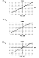
- FIGS. 2A, 2B, and 2C depict the input/output relationship of three methods of one bit signal compression (as shown in graphs 200, 202, and 204 ). These graphs give the value output by signal compressor 106 over a given range of input values.
- the first two graphs (200 and 202) depict conventional signal compression methods, while the third (204) depicts a method according to the present invention. Note that both input and output values are shown in decimal format for convenience, though the values are represented in 2's complement binary format as signal input 102 and signal output 104.
- the three graphs in FIG. 2 depict one bit compression of a four bit input signal to a three bit output signal.
- a four bit signal input 102 can represent integer signal values ranging from “7" to "-8", including "0".
- a three bit signal output 104 can represent integer signal values ranging from "3" to "-4", including "0".
- Truncation or rounding of an integer number of bits approximates the linear operation of division by a power of two. The average or expected deviation from this ideal is the bias.
- the linear operation of division by two is shown in graphs 200,202 , and 204 as a dotted line.
- FIG. 2A illustrates the input/output relationship of conventional one bit truncation.
- truncation refers to merely dropping the K least significant bits (the fractional component) from input signal 102 to form output signal 104 . In other words, the output value is always rounded down.
- the solid line in FIG. 2A illustrates this relationship. For example, an input value of "5" (binary 0101) ideally compresses to a value of "2.5".
- Conventional truncation produces an output value of "2" (binary 010), the integer component of the input value.
- Those skilled in the art will recognize that since the actual output values are always equal to or less than the ideal values, conventional truncation on average introduces a negative bias to output signal 104.
- FIG. 2B illustrates the input/output relationship of conventional one bit rounding.
- the output value is equal to the integer nearest the ideal value, with ideal values midway between two integers (i.e., any ideal value ending in a 0.5) always being rounded up.
- each of the odd input values is, therefore, rounded up (as shown by the solid line in FIG. 2B ) as the ideal compressed value is midway between two integers.
- an input value of "5" which ideally compresses to a value of "2.5”
- the positive bias introduced by conventional rounding can be clearly seen in FIG. 2B : the actual output values are always either equal to or greater than the idea values.
- FIG. 2C illustrates the input/output relationship of a method of signal compression according to the present invention, called "dithered rounding.”
- Dithered rounding like conventional rounding, produces an output value that is equal to the integer nearest the ideal value.
- dithered rounding operates differently on those input values that result in ideal compressed values midway between two integers. Dithered rounding strives to round approximately half of these values up, and the other half down. This dither of the rounding cancels much of the bias introduced by conventional rounding.
- conventional one bit rounding introduces a positive bias to output signal 104 by always rounding up for each odd input value. Dithered one bit rounding, as shown in FIG.
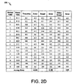
- FIG. 2D is a table 206 comparing the average error for conventional truncation, conventional rounding, and dithered rounding.
- Table 206 depicts the results for one bit compression of a four bit number to a three bit number. The error is calculated for each input value, and a total average error for each of the three methods. As can be seen, conventional truncation results in the highest average error, conventional rounding has the next highest average error, and dithered rounding has a zero average error.
- edge effects errors are sometimes introduced for the most positive input values whenever 2's complement numbers are compressed. This is because, in some cases, it is not possible to represent the most positive compressed input value rounded to the next highest integer. For example, according to conventional rounding, an input value of "7” should result in an output value of "4". However, it is not possible to represent "4" using a 3 bit 2's complement format. An input value of "7” must, therefore, be represented as "3” in violation of conventional rounding rules.
- edge effects can be minimized by scaling the input signal such that input values rarely reach the most positive value. However these edge effects only appear for greater than one bit compression, i.e., one bit compression does not suffer from edge effects.
- FIG. 3 is a flowchart 300 depicting a dithered rounding method according to the current invention. This method compresses input signal 102 by K bits to form output signal 104 based on numerical characteristics of input signal 102 .
- the following description assumes that input signal 102 and output signal 104 are represented in 2's complement format. Those skilled in the art will recognize that the ideas described below could be easily applied to binary numbers represented in other formats.
- step 302 the bits are checked to see if bit K of input signal 102 is "0". If bit K of input signal 102 is a "0", then processing proceeds to step 304. In step 304 , the N-K most significant bits of input signal 102 are output as an N- K bit output signal 104. Input values satisfying step 302 (i.e., those values having a K th bit equal to "0") are those whose ideal compressed value is closest to the next lower output integer value, and are, therefore, rounded down. If bit K of input signal 102 is not a "0", then processing proceeds to step 306.
- step 306 the bits are checked to see if bit K of input signal 102 is "1". If bit K of input signal 102 is "I”, and if bits 1 through K-1 are not all "0", then processing proceeds to step 308. In step 308, "1" is added to the N-K most significant bits of input signal 102 and the result is output as an N-K bit output signal 104. Input values satisfying the test for "1" in step 306 are those whose ideal compressed value is closest to the next higher output integer value, and are, therefore, rounded up.
- bit K of input signal 102 is "1", and bits 1 through K-1 are all "0", then processing proceeds to step 310.
- These input values are those whose ideal compressed value is midway between two integers. As described above, the dithered rounding method of the current invention strives to round approximately half of these values up, and the other half down. This is accomplished by determining whether the N-K most significant bits of input signal 102 (the integer component of input signal 102 ) are odd or even ( i.e. , whether the N-K most significant bits considered alone represent an odd or an even number), and rounding accordingly. Those skilled in the art will recognize that one half of the input values will have an odd integer component, and the other half will have an even integer component. In a preferred embodiment, those input values having an even integer component are rounded up, those having an odd integer component are rounded down.
- the oddness/evenness of input signal 102 is preferably determined by examining bit K+1 of input signal 102. An odd integer component is indicated by “1" at bit K+1, whereas an even integer component is indicated by a "0". Those skilled in the art will recognize that oddness/evenness may be determined in other ways.
- step 312 processing proceeds to step 312 where "1" is added to the N-K most significant bits of input signal 102 and the result is output as an N-K bit output signal 104 . If odd, then processing proceeds to step 314 where the N-K most significant bits of input signal 102 are output as an N-K bit output signal 104 . As a result, approximately half of the input values tested in step 310 are rounded up, and the other half are rounded down.
- FIG. 4 depicts a K-bit dithered rounding signal compressor 402 .
- Signal compressor 402 compresses N-bit input signal 102 by K bits, forming N-K bit output signal 104. The amount of compression K can vary from one bit to N-1 bits.
- Signal compressor 402 preferably includes two OR gates (410 and 416), an AND gate 408, a NOR gate 412, and an adder 406. As described above, those skilled in the art will recognize that even though the components of signal compressor 402 are described in hardware terms ( e.g. , gates), these functions may also be equivalently implemented in software, or a combination of hardware and software. Furthermore, those skilled in the art will recognize that alternative combinations of digital logic that perform equivalent functions or operations can be substituted for the logic described herein.
- Adder 406 selectively adds "1" to the integer component of input signal 102 (i.e. , the N-K most significant bits), forming N-K bit output signal 104. The remainder of the components of signal compressor 402 determine whether or not "1" is added. As described above, "1" is added for those integer components that are to be rounded up.
- AND gate 408 only outputs "1" to adder 406 if both of its inputs are "1", i.e., bit K of input signal 102 and the output of OR gate 410. Thus, if bit K of input signal 102 is not "1", then the integer component of input signal 102 will not be rounded up.
- OR gate 410 outputs "1" if either of its inputs are “1". Thus, one of its inputs must be “1” in order for the integer component of input signal 102 to be rounded up.
- OR gate 416 determines whether any of the K-1 least significant bits of input signal 102 are “1". If any of these bits are “1”, then OR gate 416 outputs "1", causing OR gate 410 to output "1" as well. Alternatively, if all of the K-1 least significant bits of input signal 102 are "0", the output of OR gate 416 is "0". If bit K+1 is also "0”, then the output of NOR gate 412 is “1”, causing OR gate 410 to output "1".
- Signal compressor 402 is a preferred embodiment for performing K-bit signal compression.
- the following section describes an alternative embodiment for one bit dithered rounding.
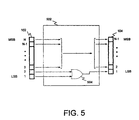
- FIG. 5 depicts a one bit dithered rounding signal compressor 502 .
- Signal compressor 502 compresses N-bit input signal 102 by a single bit, forming N-1 bit output signal 104.
- Signal compressor 502 includes an OR gate 504. Those skilled in the art will recognize that significant savings in complexity are gained where only a single bit of compression is required. Thus, signal compressor 502 is a preferred embodiment in situations where one bit compression is required.
- OR gate 504 selectively adds "1" to the integer component of input signal 102 (i.e. , the N-1 most significant bits) forming N-1 bit output signal 104 . OR gate 504 outputs "1” if either bit 1 or bit 2 of input signal 102 are “1". Thus, the integer component of input signal 102 is rounded up if bit 2 is "0" and bit 1 is "1".
Landscapes
- Engineering & Computer Science (AREA)
- Theoretical Computer Science (AREA)
- General Physics & Mathematics (AREA)
- Physics & Mathematics (AREA)
- Computing Systems (AREA)
- Mathematical Analysis (AREA)
- Mathematical Optimization (AREA)
- Pure & Applied Mathematics (AREA)
- General Engineering & Computer Science (AREA)
- Computational Mathematics (AREA)
- Compression, Expansion, Code Conversion, And Decoders (AREA)
- Reduction Or Emphasis Of Bandwidth Of Signals (AREA)
- Transmission Systems Not Characterized By The Medium Used For Transmission (AREA)
Claims (5)
- Verfahren zur Kompression eines N-Bitsignals durch K Bits, wobei das Signal in einem 2's Komplementformat repräsentiert ist und mit K < N und wobei Bit 1 des Signals das am wenigsten signifikante Bit ist, und Bit N des Signals das am meisten signifikante Bit ist, und wobei ferner die folgenden Schritte vorgesehen sind:Ausgabe der N-K am meisten signifikanten Bits des Signals, wenn Bit K des Signals gleich "0" ist;Hinzuaddieren von "1" zu dem N-K am meisten signifikanten Bits des Signals und Ausgabe des Ergebnisses der erwähnten Addition, wenn Bit K des Signals gleich "1" ist, und wenn Bits K-1 bis Bit 1 des Signals nicht alle gleich "0" sind; undBestimmen der Ungeradheit oder Geradheit der N-K am meisten signifikanten Bits des Signals, wenn Bit K des Signals gleich "1" ist, und wenn Bits K-1 bis Bit 1 des Signals alle gleich "0" sind, und bei Geradheit Hinzuaddieren von "1" zu den N-K am meisten signifikanten Bits des Signals und Ausgabe des Ergebnisses der erwähnten Addition, und wenn Ungeradzahligkeit vorliegt, Ausgabe der N-K am meisten signifikanten Bits des Signals.
- Verfahren nach Anspruch 1, wobei der Schritt des Bestimmens der Ungeradheit oder der Geradheit Folgendes aufweist: Überprüfen von Bit K+1 des Signals, wobei das Signal ungeradzahlig ist, wenn Bit K+1 gleich "1" ist, und wobei das Signal geradzahlig ist, wenn das Bit K+1 gleich "0" ist.
- Ein System zur Kompression eines N-Bit Signals (102) durch K Bits, wobei das Signal (102) durch ein 2's Komplementformat und K < N repräsentiert ist, wobei Bit 1 des Signals (102) das am wenigsten signifikante Bit ist, und wobei das Bit N des Signals das am meisten signifikante Bit ist, und wobei ferner Folgendes vorgesehen ist:erste Mittel (106) zum Bestimmen ob Bit K des Signals (102) gleich "0" ist, und wenn dies der Fall ist, Ausgabe der N-K am meisten signifikanten Bits des Signals (102);zweite Mittel (106) zur Bestimmung, ob Bit K des Signals (102) gleich "1" ist, und wenn dies der Fall ist, zur Bestimmung ob die Bits K-1 bis Bit 1 des Signals (102) alle nicht gleich "0" sind, und wenn dies der Fall ist, für das Hinzuaddieren von "1" zu den N-K am meisten signifikanten Bits des Signals (102) und Ausgabe des Ergebnisses der erwähnten Addition; und dritte Mittel (186) zur Bestimmung, ob Bit K des Signals gleich "1" ist, und wenn dies der Fall ist, zur Bestimmung ob die Bits K-1 bis Bit 1 des Signals alle gleich "0" sind, und wenn dies der Fall ist, zur Bestimmung der Ungeradheit oder der Geradheit der N-K am meisten signifikanten Bits des Signals (102), und wenn Geradheit vorliegt, zum Hinzuaddieren von "1" zu den N-K am meisten signifikanten Bits des Signals (102) und zur Ausgabe des Ergebnisses (104) der erwähnten Addition, und wenn Ungeradzahligkeit vorliegt, zur Ausgabe der N-K am meisten signifikanten Bits des Signals (102).
- Das System nach Anspruch 3, wobei die dritten Mittel (106) zur Bestimmung der Ungeradheit oder Geradheit Mittel aufweisen zur Überprüfung von Bit K+1 Bit des Signals (102), wobei das Signal (102) ungerade ist, wenn Bit K+1 = "1" ist, und wobei das Signal (102) ungerade ist, wenn Bit K+1 = "0" ist.
- Das System nach Anspruch 3 oder 4, wobei das Signal in einem 2's Komplementformat repräsentiert wird und K < N, und wobei ferner Bit 1 des Signals (102) das am wenigsten signifikante Bit ist, und Bit N des Signals das am meisten signifikante Bit ist, wobei ferner Folgendes vorgesehen ist:erste ODER Mittel (416) zur Bestimmung ob eines oder mehrere der Bits 1 bis K-1 des Signals gleich "1" ist, wobei die ersten ODER Mittel (416) eine erste Ausgangsgröße besitzen;erste NOR Mittel (412) zur Bestimmung, ob die erste Ausgangsgröße und Bit K+1 des Signals beide "0" sind, wobei die ersten NOR Mittel (412) eine zweite Ausgangsgröße besitzen;zweite ODER Mittel (410) zu Bestimmung, ob entweder die erwähnte erste Ausgangsgröße oder die erwähnte zweite Ausgangsgröße "1" ist, wobei die erwähnten zweiten ODER Mittel (410) eine dritte Ausgangsgröße aufweisen;erste UND Mittel (408) zur Bestimmung ob die erwähnte dritte Ausgangsgröße und Bit K des Signals beide "1" sind, wobei die ersten UND Mittel (408) eine vierte Ausgangsgröße besitzen; undwobei ein Addierer (406) die erwähnte vierte Ausgangsgröße zu den N-K am meisten signifikanten Bits des Signals hinzuaddiert und das Ergebnis (104) der Addition ausgibt.
Applications Claiming Priority (3)
| Application Number | Priority Date | Filing Date | Title |
|---|---|---|---|
| US134248 | 1998-08-14 | ||
| US09/134,248 US6148317A (en) | 1998-08-14 | 1998-08-14 | Method and apparatus for compressing signals in a fixed point format without introducing a bias |
| PCT/US1999/018546 WO2000010253A2 (en) | 1998-08-14 | 1999-08-13 | A method and apparatus for compressing signals in a fixed point format without introducing a bias |
Publications (2)
| Publication Number | Publication Date |
|---|---|
| EP1110325A2 EP1110325A2 (de) | 2001-06-27 |
| EP1110325B1 true EP1110325B1 (de) | 2004-06-23 |
Family
ID=22462453
Family Applications (1)
| Application Number | Title | Priority Date | Filing Date |
|---|---|---|---|
| EP99941157A Expired - Lifetime EP1110325B1 (de) | 1998-08-14 | 1999-08-13 | Verfahren und vorrichtung zur signalkompression im festpunktformat ohne bias |
Country Status (11)
| Country | Link |
|---|---|
| US (1) | US6148317A (de) |
| EP (1) | EP1110325B1 (de) |
| JP (1) | JP4354648B2 (de) |
| KR (1) | KR20010072504A (de) |
| CN (1) | CN1321269A (de) |
| AT (1) | ATE270009T1 (de) |
| AU (1) | AU767325B2 (de) |
| CA (1) | CA2340421A1 (de) |
| DE (1) | DE69918313T2 (de) |
| RU (1) | RU2233024C2 (de) |
| WO (1) | WO2000010253A2 (de) |
Families Citing this family (4)
| Publication number | Priority date | Publication date | Assignee | Title |
|---|---|---|---|---|
| US6243728B1 (en) * | 1999-07-12 | 2001-06-05 | Sony Corporation Of Japan | Partitioned shift right logic circuit having rounding support |
| GB0031771D0 (en) * | 2000-12-29 | 2001-02-07 | Lsi Logic Corp | Bit reduction using dither,rounding and error feedback |
| JP3755602B2 (ja) * | 2003-03-04 | 2006-03-15 | ソニー株式会社 | 信号処理装置、信用処理装置用プログラム、信号処理装置用プログラムを記録した記録媒体、及び信号処理方法 |
| US8301803B2 (en) * | 2009-10-23 | 2012-10-30 | Samplify Systems, Inc. | Block floating point compression of signal data |
Family Cites Families (9)
| Publication number | Priority date | Publication date | Assignee | Title |
|---|---|---|---|---|
| JP3199371B2 (ja) * | 1990-07-30 | 2001-08-20 | 松下電器産業株式会社 | 丸め装置 |
| US5214598A (en) * | 1990-11-09 | 1993-05-25 | Adaptive Solutions, Inc. | Unbiased bit disposal apparatus and method |
| JPH05503178A (ja) * | 1990-11-09 | 1993-05-27 | アダプティブ・ソリューションズ・インコーポレーテッド | 偏りのないビット廃棄装置および方法 |
| NZ258398A (en) * | 1992-11-16 | 1997-06-24 | Multimedia Systems Corp | Optimal transmission of multimedia entertainment information |
| US5491516A (en) * | 1993-01-14 | 1996-02-13 | Rca Thomson Licensing Corporation | Field elimination apparatus for a video compression/decompression system |
| TW224553B (en) * | 1993-03-01 | 1994-06-01 | Sony Co Ltd | Method and apparatus for inverse discrete consine transform and coding/decoding of moving picture |
| US5424967A (en) * | 1993-11-29 | 1995-06-13 | Hewlett-Packard Company | Shift and rounding circuit and method |
| US5594660A (en) * | 1994-09-30 | 1997-01-14 | Cirrus Logic, Inc. | Programmable audio-video synchronization method and apparatus for multimedia systems |
| US5696710A (en) * | 1995-12-29 | 1997-12-09 | Thomson Consumer Electronics, Inc. | Apparatus for symmetrically reducing N least significant bits of an M-bit digital signal |
-
1998
- 1998-08-14 US US09/134,248 patent/US6148317A/en not_active Expired - Lifetime
-
1999
- 1999-08-13 CN CN99811666A patent/CN1321269A/zh active Pending
- 1999-08-13 JP JP2000565606A patent/JP4354648B2/ja not_active Expired - Fee Related
- 1999-08-13 RU RU2001107011/09A patent/RU2233024C2/ru not_active IP Right Cessation
- 1999-08-13 CA CA002340421A patent/CA2340421A1/en not_active Abandoned
- 1999-08-13 WO PCT/US1999/018546 patent/WO2000010253A2/en not_active Ceased
- 1999-08-13 AU AU54866/99A patent/AU767325B2/en not_active Ceased
- 1999-08-13 KR KR1020017001935A patent/KR20010072504A/ko not_active Withdrawn
- 1999-08-13 AT AT99941157T patent/ATE270009T1/de not_active IP Right Cessation
- 1999-08-13 DE DE69918313T patent/DE69918313T2/de not_active Expired - Fee Related
- 1999-08-13 EP EP99941157A patent/EP1110325B1/de not_active Expired - Lifetime
Also Published As
| Publication number | Publication date |
|---|---|
| JP4354648B2 (ja) | 2009-10-28 |
| ATE270009T1 (de) | 2004-07-15 |
| EP1110325A2 (de) | 2001-06-27 |
| RU2233024C2 (ru) | 2004-07-20 |
| AU5486699A (en) | 2000-03-06 |
| WO2000010253A3 (en) | 2000-05-18 |
| KR20010072504A (ko) | 2001-07-31 |
| DE69918313T2 (de) | 2005-09-29 |
| DE69918313D1 (de) | 2004-07-29 |
| CN1321269A (zh) | 2001-11-07 |
| AU767325B2 (en) | 2003-11-06 |
| JP2002523913A (ja) | 2002-07-30 |
| CA2340421A1 (en) | 2000-02-24 |
| WO2000010253A2 (en) | 2000-02-24 |
| US6148317A (en) | 2000-11-14 |
Similar Documents
| Publication | Publication Date | Title |
|---|---|---|
| US5764555A (en) | Method and system of rounding for division or square root: eliminating remainder calculation | |
| KR100498457B1 (ko) | 메모리를 감소시키는 개선된 룩업 테이블 압축방법 및이를 이용하여 압축된 룩업 테이블을 가지는 비선형 함수발생장치 및 그 발생방법 | |
| US6988119B2 (en) | Fast single precision floating point accumulator using base 32 system | |
| EP1001334B1 (de) | Logarithmus- / Antilogarithmusrechner | |
| US6785701B2 (en) | Apparatus and method of performing addition and rounding operation in parallel for floating-point arithmetic logical unit | |
| US6175851B1 (en) | Fast adder/subtractor for signed floating point numbers | |
| EP0596175A1 (de) | Gerät zum Ausführen der Argumentreduktion in Exponentialberechnungen von IEEE-Norm-Gleitkommazahlen | |
| US5337266A (en) | Method and apparatus for fast logarithmic addition and subtraction | |
| US6847986B2 (en) | Divider | |
| EP1110325B1 (de) | Verfahren und vorrichtung zur signalkompression im festpunktformat ohne bias | |
| US7437657B2 (en) | High speed add-compare-select processing | |
| US4977534A (en) | Operation circuit based on floating-point representation with selective bypass for increasing processing speed | |
| US5463571A (en) | Multi-nary OR logic device | |
| US4737925A (en) | Method and apparatus for minimizing a memory table for use with nonlinear monotonic arithmetic functions | |
| EP0568373A2 (de) | Parallelisierter Grössenvergleicher | |
| US5408427A (en) | Detection of exponent underflow and overflow in a floating point adder | |
| US20040254973A1 (en) | Rounding mode insensitive method and apparatus for integer rounding | |
| US6044391A (en) | Method of generating the sticky-bit from the input operands | |
| EP0242600A2 (de) | Verfahren zur Berechnung des Übertragvorgriffs und Schaltung dazu | |
| Kwak et al. | High-speed CORDIC based on an overlapped architecture and a novel σ-prediction method | |
| US5253194A (en) | Digital multiplier | |
| US6891915B2 (en) | Calculating circuit for dividing a fixed-point signal | |
| JP2000010763A (ja) | 除算回路 | |
| EP0561411A2 (de) | Addierender Multiplizierer | |
| US6996598B2 (en) | Calculation circuit for the division of a fixed-point signal |
Legal Events
| Date | Code | Title | Description |
|---|---|---|---|
| PUAI | Public reference made under article 153(3) epc to a published international application that has entered the european phase |
Free format text: ORIGINAL CODE: 0009012 |
|
| 17P | Request for examination filed |
Effective date: 20010308 |
|
| AK | Designated contracting states |
Kind code of ref document: A2 Designated state(s): AT BE CH CY DE DK ES FI FR GB GR IE IT LI LU MC NL PT SE |
|
| AX | Request for extension of the european patent |
Free format text: AL PAYMENT 20010308;LT PAYMENT 20010308;LV PAYMENT 20010308;MK PAYMENT 20010308;RO PAYMENT 20010308;SI PAYMENT 20010308 |
|
| 17Q | First examination report despatched |
Effective date: 20030206 |
|
| GRAP | Despatch of communication of intention to grant a patent |
Free format text: ORIGINAL CODE: EPIDOSNIGR1 |
|
| GRAS | Grant fee paid |
Free format text: ORIGINAL CODE: EPIDOSNIGR3 |
|
| GRAA | (expected) grant |
Free format text: ORIGINAL CODE: 0009210 |
|
| AK | Designated contracting states |
Kind code of ref document: B1 Designated state(s): AT BE CH CY DE DK ES FI FR GB GR IE IT LI LU MC NL PT SE |
|
| AX | Request for extension of the european patent |
Extension state: AL LT LV MK RO SI |
|
| PG25 | Lapsed in a contracting state [announced via postgrant information from national office to epo] |
Ref country code: NL Free format text: LAPSE BECAUSE OF FAILURE TO SUBMIT A TRANSLATION OF THE DESCRIPTION OR TO PAY THE FEE WITHIN THE PRESCRIBED TIME-LIMIT Effective date: 20040623 Ref country code: LI Free format text: LAPSE BECAUSE OF FAILURE TO SUBMIT A TRANSLATION OF THE DESCRIPTION OR TO PAY THE FEE WITHIN THE PRESCRIBED TIME-LIMIT Effective date: 20040623 Ref country code: CY Free format text: LAPSE BECAUSE OF FAILURE TO SUBMIT A TRANSLATION OF THE DESCRIPTION OR TO PAY THE FEE WITHIN THE PRESCRIBED TIME-LIMIT Effective date: 20040623 Ref country code: CH Free format text: LAPSE BECAUSE OF FAILURE TO SUBMIT A TRANSLATION OF THE DESCRIPTION OR TO PAY THE FEE WITHIN THE PRESCRIBED TIME-LIMIT Effective date: 20040623 Ref country code: BE Free format text: LAPSE BECAUSE OF FAILURE TO SUBMIT A TRANSLATION OF THE DESCRIPTION OR TO PAY THE FEE WITHIN THE PRESCRIBED TIME-LIMIT Effective date: 20040623 Ref country code: AT Free format text: LAPSE BECAUSE OF FAILURE TO SUBMIT A TRANSLATION OF THE DESCRIPTION OR TO PAY THE FEE WITHIN THE PRESCRIBED TIME-LIMIT Effective date: 20040623 |
|
| REG | Reference to a national code |
Ref country code: GB Ref legal event code: FG4D |
|
| REG | Reference to a national code |
Ref country code: CH Ref legal event code: EP |
|
| REG | Reference to a national code |
Ref country code: IE Ref legal event code: FG4D |
|
| REF | Corresponds to: |
Ref document number: 69918313 Country of ref document: DE Date of ref document: 20040729 Kind code of ref document: P |
|
| REG | Reference to a national code |
Ref country code: SE Ref legal event code: TRGR |
|
| PG25 | Lapsed in a contracting state [announced via postgrant information from national office to epo] |
Ref country code: LU Free format text: LAPSE BECAUSE OF NON-PAYMENT OF DUE FEES Effective date: 20040813 Ref country code: IE Free format text: LAPSE BECAUSE OF NON-PAYMENT OF DUE FEES Effective date: 20040813 |
|
| PG25 | Lapsed in a contracting state [announced via postgrant information from national office to epo] |
Ref country code: MC Free format text: LAPSE BECAUSE OF NON-PAYMENT OF DUE FEES Effective date: 20040831 |
|
| PG25 | Lapsed in a contracting state [announced via postgrant information from national office to epo] |
Ref country code: GR Free format text: LAPSE BECAUSE OF FAILURE TO SUBMIT A TRANSLATION OF THE DESCRIPTION OR TO PAY THE FEE WITHIN THE PRESCRIBED TIME-LIMIT Effective date: 20040923 Ref country code: DK Free format text: LAPSE BECAUSE OF FAILURE TO SUBMIT A TRANSLATION OF THE DESCRIPTION OR TO PAY THE FEE WITHIN THE PRESCRIBED TIME-LIMIT Effective date: 20040923 |
|
| PG25 | Lapsed in a contracting state [announced via postgrant information from national office to epo] |
Ref country code: ES Free format text: LAPSE BECAUSE OF FAILURE TO SUBMIT A TRANSLATION OF THE DESCRIPTION OR TO PAY THE FEE WITHIN THE PRESCRIBED TIME-LIMIT Effective date: 20041004 |
|
| PGFP | Annual fee paid to national office [announced via postgrant information from national office to epo] |
Ref country code: FI Payment date: 20041124 Year of fee payment: 6 |
|
| LTIE | Lt: invalidation of european patent or patent extension |
Effective date: 20040623 |
|
| NLV1 | Nl: lapsed or annulled due to failure to fulfill the requirements of art. 29p and 29m of the patents act | ||
| REG | Reference to a national code |
Ref country code: CH Ref legal event code: PL |
|
| PGFP | Annual fee paid to national office [announced via postgrant information from national office to epo] |
Ref country code: GB Payment date: 20050119 Year of fee payment: 6 |
|
| PGFP | Annual fee paid to national office [announced via postgrant information from national office to epo] |
Ref country code: FR Payment date: 20050131 Year of fee payment: 6 |
|
| PGFP | Annual fee paid to national office [announced via postgrant information from national office to epo] |
Ref country code: DE Payment date: 20050228 Year of fee payment: 6 |
|
| ET | Fr: translation filed | ||
| PLBE | No opposition filed within time limit |
Free format text: ORIGINAL CODE: 0009261 |
|
| STAA | Information on the status of an ep patent application or granted ep patent |
Free format text: STATUS: NO OPPOSITION FILED WITHIN TIME LIMIT |
|
| REG | Reference to a national code |
Ref country code: IE Ref legal event code: MM4A |
|
| 26N | No opposition filed |
Effective date: 20050324 |
|
| PG25 | Lapsed in a contracting state [announced via postgrant information from national office to epo] |
Ref country code: IT Free format text: LAPSE BECAUSE OF NON-PAYMENT OF DUE FEES;WARNING: LAPSES OF ITALIAN PATENTS WITH EFFECTIVE DATE BEFORE 2007 MAY HAVE OCCURRED AT ANY TIME BEFORE 2007. THE CORRECT EFFECTIVE DATE MAY BE DIFFERENT FROM THE ONE RECORDED. Effective date: 20050813 Ref country code: GB Free format text: LAPSE BECAUSE OF NON-PAYMENT OF DUE FEES Effective date: 20050813 Ref country code: FI Free format text: LAPSE BECAUSE OF NON-PAYMENT OF DUE FEES Effective date: 20050813 |
|
| PGFP | Annual fee paid to national office [announced via postgrant information from national office to epo] |
Ref country code: SE Payment date: 20051007 Year of fee payment: 7 |
|
| PG25 | Lapsed in a contracting state [announced via postgrant information from national office to epo] |
Ref country code: DE Free format text: LAPSE BECAUSE OF NON-PAYMENT OF DUE FEES Effective date: 20060301 |
|
| GBPC | Gb: european patent ceased through non-payment of renewal fee |
Effective date: 20050813 |
|
| PG25 | Lapsed in a contracting state [announced via postgrant information from national office to epo] |
Ref country code: FR Free format text: LAPSE BECAUSE OF NON-PAYMENT OF DUE FEES Effective date: 20060428 |
|
| REG | Reference to a national code |
Ref country code: FR Ref legal event code: ST Effective date: 20060428 |
|
| PG25 | Lapsed in a contracting state [announced via postgrant information from national office to epo] |
Ref country code: SE Free format text: LAPSE BECAUSE OF NON-PAYMENT OF DUE FEES Effective date: 20060814 |
|
| EUG | Se: european patent has lapsed | ||
| PG25 | Lapsed in a contracting state [announced via postgrant information from national office to epo] |
Ref country code: PT Free format text: LAPSE BECAUSE OF NON-PAYMENT OF DUE FEES Effective date: 20041123 |