EP1110612A2 - Système de pipetage avec pipette et embout-seringue - Google Patents
Système de pipetage avec pipette et embout-seringue Download PDFInfo
- Publication number
- EP1110612A2 EP1110612A2 EP00120119A EP00120119A EP1110612A2 EP 1110612 A2 EP1110612 A2 EP 1110612A2 EP 00120119 A EP00120119 A EP 00120119A EP 00120119 A EP00120119 A EP 00120119A EP 1110612 A2 EP1110612 A2 EP 1110612A2
- Authority
- EP
- European Patent Office
- Prior art keywords
- piston
- pipette
- jaws
- syringe
- piston head
- Prior art date
- Legal status (The legal status is an assumption and is not a legal conclusion. Google has not performed a legal analysis and makes no representation as to the accuracy of the status listed.)
- Granted
Links
Images



Classifications
-
- B—PERFORMING OPERATIONS; TRANSPORTING
- B01—PHYSICAL OR CHEMICAL PROCESSES OR APPARATUS IN GENERAL
- B01L—CHEMICAL OR PHYSICAL LABORATORY APPARATUS FOR GENERAL USE
- B01L3/00—Containers or dishes for laboratory use, e.g. laboratory glassware; Droppers
- B01L3/02—Burettes; Pipettes
- B01L3/0275—Interchangeable or disposable dispensing tips
- B01L3/0279—Interchangeable or disposable dispensing tips co-operating with positive ejection means
-
- B—PERFORMING OPERATIONS; TRANSPORTING
- B01—PHYSICAL OR CHEMICAL PROCESSES OR APPARATUS IN GENERAL
- B01L—CHEMICAL OR PHYSICAL LABORATORY APPARATUS FOR GENERAL USE
- B01L3/00—Containers or dishes for laboratory use, e.g. laboratory glassware; Droppers
- B01L3/02—Burettes; Pipettes
- B01L3/021—Pipettes, i.e. with only one conduit for withdrawing and redistributing liquids
- B01L3/0217—Pipettes, i.e. with only one conduit for withdrawing and redistributing liquids of the plunger pump type
- B01L3/0234—Repeating pipettes, i.e. for dispensing multiple doses from a single charge
Definitions
- the invention relates to a pipette for a pipette system with a such a pipette and a syringe, namely a pipette with the features the preamble of claim 1.
- Pipettes with axially insertable syringes are regarding the design the cylinder gripping device and the piston gripping device constructively complex. Pipettes with a radial design are simpler in design Syringe insertable and removable from this syringe. From one The present invention is based on such a pipette (DE 29 26 691 C2).
- the radially accessible Cylinder gripping device fixed to the pipette housing as a top view U-shaped flange-like edge with pressure spring located above designed as a circumferential, projecting flange Attachment section of the cylinder of the syringe according to the radial Insert carries.
- the piston holder is common to two lateral ones a U-forming jaws formed that the piston head when inserting Grasp the syringe sideways and hold it at the same time.
- the piston actuating device in this pipette also includes an actuating device, which is attached to the piston actuator. It is about here around a fold-out clamping member that flipped up to insert the syringe and to finally fix the piston head between the Jaws is pivoted down. By swinging down will already be firmly attached to the piston head under their own spring force Clamping jaws additionally pressed against the piston head.
- each jaw with profiling, in particular with cutting-like Provide profiles.
- profiles With appropriate material selection for the piston head will be the profiles, especially if it is cutting-like profiles act laterally in the material of the piston head indented so that with regard to the considerable axial forces, which are transferred from the piston actuator to the piston head during operation become, not just a pure frictional connection between jaws and Piston head, but to a certain extent also gives a positive fit.
- the piston head is pressed in a non-positive between the side jaws Pre-fixation of the piston also in the axial direction.
- the syringe can therefore be a little too high when inserted sitting piston head (piston not yet fully retracted) no longer move axially. You have to take the syringe out and then reinsert with piston fully inserted.
- the actuating device designed as a closure flap for the piston gripping device must have a manual override to move them.
- This manual control element interferes with operation in the Hand-held pipette because it is imperative to use the piston actuator axially moves together in the pipette housing.
- a corresponding displacement path in the pipette housing is kept open manual operation collides with the one holding the pipette Hand. This is particularly the case with an ergonomically appropriate design problem of the pipette housing, in which the pipette housing by the hand is completely gripped.
- An embodiment of the pipette according to the invention is of particular importance according to claim 2.
- the fact that the adjusting movement of the jaws is steered so that it is with respect to the outer surface of the piston head has an essential tangential component, the required Strength for a sufficient positive connection of clamping jaws and piston head as low as possible.
- the manufacture for the transfer takes place considerable axial tensile forces necessary positive connection not by impressing the cutting-like profiles in the material of the piston head, but by cutting into the material with the tangential movement the piston head.
- there must be any risk of slip between the piston adjusting device and the piston head are avoided, to maintain the desired dosing accuracy. This comes with lowest possible forces generated positive connection through the cutting-like profiles on the jaws are of considerable importance to.
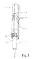
- the pipette 1 shows a perspective view of a pipette system from a pipette 1 and a syringe 2.
- the pipette 1 is the one shown and preferred Embodiment around a motor-operated repeater pipette.
- the teaching of the invention is not on motor-operated repeating pipettes limited, it can be used for any type of pipette with a syringe, be it manually operated or motorized.
- Fig. 1 one recognizes handle shapes 3 and one from the pipette Motor control 4.
- Fig. 4 in connection with Fig. 1 reveals that with such a pipette 1 used syringe 2, which is commercially available as a replacement part is, as usual, a cylinder 5 with a fastening section designed here as a flange 6 and with a piston 7. This is in Fig. 4 not recognizable, but hidden in cylinder 5. Only him is from him in the inserted state protruding from the end of the cylinder 5 Recognize piston head 8.
- the pipette 1 itself has a pipette housing 9, in which only one in FIG. 4 indicated indicated piston actuator 10 axially displaceable is.
- the piston actuating device 10 is used in a motor-operated pipette 1 moved by the motor, with a manually operated pipette by hand, if necessary via a step mechanism that z. B. works with jack and rack.
- a radially accessible cylinder gripping device is fixedly attached to the pipette housing 9 11.
- the cylinder gripping device 11 is here as in the already State of the art mentioned above (DE 29 26 691 C2) simply as a U-shaped, flange-like edge on the pipette housing 9, on which the Fastening section 6 of the cylinder 5 designed as a circumferential flange lies on. This is there on the edge by a pressure spring 12, the is also indicated in Fig. 4, non-positively fixed.
- a radially accessible piston actuator device is also provided 10 with this slidably mounted piston gripping device 13 for the Piston head 8 of a syringe 2 and an actuating device 14 for this Piston gripping device 13. Also in this regard, reference may be made in particular to FIG. 4 become.
- Fig. 4 shows the cutting-like profiles 17 on the jaws 16 of the piston gripping device 13. There are a total of six stacked cutting-like profiles 17 per jaw 16.
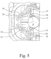
- FIG Swivel axes 18 pivotally mounted jaws 16 with the again preferably rotatably mounted cutting-like profiles 17, executed here as cutting rollers.
- FIGS. 4 and 5 also shows that the adjustment movement of the pivoting profiles 17 provided jaws 16 is steered so that it on the piston head 8 or the outer surface of the piston head 8 a substantial tangential Component.
- the embodiment shown in Fig. 5 further shows that more preferred Teach the end position of the positioning movement of the jaws 16 the piston head 8 just before the dead center to just beyond the dead center lies.
- the dead center is the point at which the central axis the cutting-like profile 17 of the jaw 16 exactly on the connecting line the central axis of the piston head 8 with the swivel axis 18 the jaw 16 is.
- the embodiment shown in Fig. 5 shows an end position of the positioning movement of the jaws 16, which is just on this side the dead center.
- the aim is always a sufficiently long one Cutting line of the cutting-like profiles 17 and nevertheless a safe one Fixing the piston head 8 between the jaws 16. For this purpose can u. U. also go to a position slightly beyond the dead center.
- the pipette 1 according to the invention can also be used, as in the prior art Technology, the actuating device 14 on the piston gripping device 13 arrange.
- the previously explained concept with the adjusting movement of the clamping jaws 16 by spring force allows that, also in the embodiment realized the actuator 14 for the piston gripping device 13 is attached to the pipette housing 9. It is therefore not with the piston adjusting device 10 displaceable in the pipette housing 9, but seen in this way arranged in a stationary manner in the pipette housing 9.
- Fig. 1 shows the slide valve forming the actuator 14 pushed down into the closed position during Figs. 2, 3 and 4 the slide valve, which forms the actuating device 14, upwards show pushed. In this position, the actuator 14 gives the Piston receptacle 15 free while in the position shown in FIG. 1 closes the piston receptacle 15.
- the illustrated and preferred embodiment shows one Construction in which the actuator 14, the jaws 16 at closed piston receptacle 15 releases and with the piston receptacle open 15 opens against the spring force.
- the closed shown in Fig. 1 So you can position the piston head 8 by means of Piston actuator 10 securely coupled up and down move.
- the position shown in FIGS. 2, 3 and 4 is the Actuating device 14 one in which by means of the actuating device 14 oppose the jaws 16 of the piston gripping device 13 the force of the pressure springs 12 are spread apart, so that the Piston head 8 is released. This corresponds to the release of the Piston holder 15 in this position, in which the syringe 2 can be separated from the pipette 1 in total.
- FIGS. 6 and 7 are related.
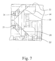
- Fig. 6 and Fig. 7 show that in the illustrated and so far preferred embodiment, the actuator 14 inside a Wedge guide 20 for adjusting heads 21 of the jaws 16, wherein in illustrated embodiment, the wedge guide 20 at the bottom, open It is wide at the end and converges towards the top. This can be seen in Fig. 6 and 7 recognize very well.
- Fig. 5 shows on the left on the two-armed levers form the jaws 16, the actuating heads 21 of the jaws 16. These run in the wedge guides 20 on the inside of the embodiment shown the actuator 14 forming shutter.
- FIG. 6 shows the position of the adjusting heads 21 with respect to the wedge guide 20, which corresponds to the position of the clamping jaws 16 in FIG. 5, that is to say the position with fixed piston head 8.
- Fig. 7 shows a position in which straight has begun, the slide valve, the actuator 14 forms in the position shown in FIGS. 2, 3 and 4 upwards push. It can be seen that the adjusting heads 21 of the jaws 16 are somewhat have been spread apart, forced by the wedge guide 20. An the lower ends of the wedge guide 20 can be seen holding grooves 22 into which the Engage the adjusting heads 21 with the slide slide fully pushed up can. The open position of the actuating device 14 is thereby fixed.
- Fig. 4 of the drawing finally shows that even in the illustrated embodiment a pipette 1 according to the invention at the open end closed end of the piston holder facing away from the pipette housing 9 15 an insertion bevel 23 is arranged for the piston head 8, through which the piston head 8 forcibly when the syringe 2 is inserted into the Position is brought in which the piston 7 completely in the cylinder 5th is inserted.
- the insertion bevel 23 for the piston head 8 can can also be designed as an axially acting pressure spring or such axially have acting compression spring.
Landscapes
- Health & Medical Sciences (AREA)
- Clinical Laboratory Science (AREA)
- Chemical & Material Sciences (AREA)
- Chemical Kinetics & Catalysis (AREA)
- Devices For Use In Laboratory Experiments (AREA)
- Sampling And Sample Adjustment (AREA)
Applications Claiming Priority (2)
| Application Number | Priority Date | Filing Date | Title |
|---|---|---|---|
| DE19963141 | 1999-12-24 | ||
| DE19963141A DE19963141A1 (de) | 1999-12-24 | 1999-12-24 | Pipette für ein Pipettiersystem |
Publications (3)
| Publication Number | Publication Date |
|---|---|
| EP1110612A2 true EP1110612A2 (fr) | 2001-06-27 |
| EP1110612A3 EP1110612A3 (fr) | 2003-06-25 |
| EP1110612B1 EP1110612B1 (fr) | 2004-08-04 |
Family
ID=7934598
Family Applications (1)
| Application Number | Title | Priority Date | Filing Date |
|---|---|---|---|
| EP00120119A Expired - Lifetime EP1110612B1 (fr) | 1999-12-24 | 2000-09-16 | Système de pipetage avec pipette et embout-seringue |
Country Status (5)
| Country | Link |
|---|---|
| US (1) | US6540964B2 (fr) |
| EP (1) | EP1110612B1 (fr) |
| JP (1) | JP2001224971A (fr) |
| AT (1) | ATE272445T1 (fr) |
| DE (2) | DE19963141A1 (fr) |
Cited By (2)
| Publication number | Priority date | Publication date | Assignee | Title |
|---|---|---|---|---|
| EP2415525A3 (fr) * | 2010-08-03 | 2014-07-02 | Brand GmbH + Co KG | Pipette pour un système de pipetage avec pipette et seringue |
| EP2783753A1 (fr) * | 2013-03-28 | 2014-10-01 | Eppendorf Ag | Distributeur destiné à actionner une seringue |
Families Citing this family (23)
| Publication number | Priority date | Publication date | Assignee | Title |
|---|---|---|---|---|
| DE19915066C2 (de) * | 1999-04-01 | 2001-09-13 | Brand Gmbh & Co Kg | Verfahren zur Erkennung des Typs von austauschbaren gerätespezifischen Kolben-Zylinder-Einheiten für Pipettier- oder Dosiergeräte sowie Pipettier- und Dosiersystem |
| DE10013511A1 (de) * | 2000-03-20 | 2001-10-11 | Brand Gmbh & Co Kg | Mehrkanal-Pipettiereinrichtung sowie Pipettenschaft dafür |
| WO2002000346A2 (fr) * | 2000-06-26 | 2002-01-03 | Vistalab Technologies, Inc. | Pipette manuelle |
| US6749812B2 (en) * | 2000-06-26 | 2004-06-15 | Vistalab Technologies | Automatic pipette detipping |
| US7125520B2 (en) * | 2001-04-25 | 2006-10-24 | Oyster Bay Pump Works, Inc. | Reagent addition system and method |
| DE10247731B4 (de) * | 2002-10-12 | 2007-04-12 | Eppendorf Ag | Greifwerkzeug, Dosierwerkzeug und Werkzeughalter für einen Laborautomaten |
| US7524461B2 (en) * | 2004-05-17 | 2009-04-28 | Brand Gmbh + Co. Kg | Motorized pipette |
| DE102005023203B4 (de) * | 2005-05-20 | 2009-06-04 | Eppendorf Ag | Pipette |
| CN101686827B (zh) * | 2007-01-19 | 2014-08-13 | 桑尼布鲁克健康科学中心 | 具有组合的超声和光学成像装置的成像探头 |
| DE102007010299B4 (de) * | 2007-03-02 | 2009-01-29 | Eppendorf Ag | Handpipettiervorrichtung |
| WO2009060485A1 (fr) * | 2007-11-08 | 2009-05-14 | Aea S.R.L. | Ensemble pour actionner une seringue |
| USD620602S1 (en) | 2008-01-03 | 2010-07-27 | Vistalab Technologies, Inc. | Pipette |
| DE102009016590A1 (de) * | 2009-03-31 | 2010-10-07 | Eppendorf Ag | Dosiervorrichtung |
| DE202010009747U1 (de) | 2010-07-01 | 2010-11-18 | Brand Gmbh + Co Kg | Pipette für ein Pipettensystem mit Pipette und Spritze |
| US8632738B2 (en) * | 2010-08-30 | 2014-01-21 | Health Robotics S.r.l | Syringe actuating method and assembly |
| FI20106185A0 (fi) | 2010-11-11 | 2010-11-11 | Thermo Fisher Scientific Oy | Tukipipetti |
| JP6353635B2 (ja) * | 2013-05-13 | 2018-07-04 | 株式会社アイカムス・ラボ | 分注装置 |
| USD926224S1 (en) | 2018-10-11 | 2021-07-27 | Brand Gmbh + Co Kg | Laboratory device display screen with graphical user interface |
| US11471878B2 (en) | 2019-10-25 | 2022-10-18 | Mettler-Toledo Rainin, LLC | Powered positive displacement pipette |
| US11446672B2 (en) | 2019-10-25 | 2022-09-20 | Mettler-Toledo Rainin, LLC | Powered positive displacement pipette syringe piston grasping mechanism |
| US11389792B2 (en) * | 2019-10-25 | 2022-07-19 | Mettler-Toledo Rainin, LLC | Syringe for powered positive displacement pipette |
| US12472491B2 (en) | 2022-06-28 | 2025-11-18 | Mettler-Toledo Rainin, LLC | Positive displacement pipette syringe with reduced fluid drag |
| CH722093A1 (de) * | 2024-09-02 | 2026-03-13 | Integra Biosciences Ag | Aufnahmevorrichtung für Pipetten und Pipettiervorrichtung bestehend aus einer Pipettierhilfe und einer Aufnahmevorrichtung |
Family Cites Families (20)
| Publication number | Priority date | Publication date | Assignee | Title |
|---|---|---|---|---|
| DE2926691C2 (de) * | 1979-07-02 | 1983-05-26 | Eppendorf Gerätebau Netheler + Hinz GmbH, 2000 Hamburg | Repetierpipette |
| DE2541642C3 (de) * | 1975-09-18 | 1979-07-26 | Labora Mannheim Gmbh Fuer Labortechnik, 6800 Mannheim | Pipertier-Handpipette |
| US4099548A (en) * | 1976-08-25 | 1978-07-11 | Oxford Laboratories Inc. | Hand-held pipette for repetitively dispensing precise volumes of liquid |
| US4250755A (en) * | 1979-10-22 | 1981-02-17 | Drummond Scientific Co. | Pipette |
| US4442722A (en) * | 1982-02-23 | 1984-04-17 | Beckman Instruments Inc. | Plunger operated pipet |
| US4444062A (en) * | 1982-05-05 | 1984-04-24 | Bennett John T | Liquid transfer device |
| US4567780A (en) * | 1984-03-12 | 1986-02-04 | American Hospital Supply Corporation | Hand-held pipette with disposable capillary |
| FI852704L (fi) * | 1985-07-08 | 1987-01-09 | Labsystems Oy | Eldriven pipett. |
| JP2554666B2 (ja) * | 1987-09-18 | 1996-11-13 | 株式会社ニチリョー | 可変式ピペット |
| US5104624A (en) * | 1989-10-20 | 1992-04-14 | Costar Corporation | Pipetter |
| FR2699676B1 (fr) * | 1992-12-18 | 1995-03-17 | Pasteur Sanofi Diagnostics | Dispositif de manipulation d'une seringue et automate d'analyse biologique comportant un tel dispositif. |
| DE4341229C2 (de) * | 1993-12-03 | 1995-09-07 | Eppendorf Geraetebau Netheler | Pipettensystem |
| FR2723700B1 (fr) * | 1994-08-16 | 1996-11-15 | Marteau D Autry Eric | Pipette pour distribuer des volumes successifs de liquide |
| FI951766A0 (fi) * | 1995-04-12 | 1995-04-12 | Labsystems Oy | Faspipett |
| US5849248A (en) * | 1996-03-05 | 1998-12-15 | Rainin Instrument Co., Inc. | Adjustable volume pipette with improved volume adjustment lock mechanism |
| JP2838070B2 (ja) * | 1996-03-07 | 1998-12-16 | 株式会社ニチリョー | 反復式ピペット |
| US6019004A (en) * | 1996-09-10 | 2000-02-01 | Sherwood Services, Ag | Detachable pipette barrel |
| US5983733A (en) * | 1996-11-15 | 1999-11-16 | Hamilton Company | Manual pipette |
| US6299841B1 (en) * | 1999-03-05 | 2001-10-09 | Rainin Instrument Co., Inc. | Bilaterally symmetrical battery powered microprocessor controlled lightweight hand-holdable electronic pipette |
| US6715369B2 (en) * | 2000-08-03 | 2004-04-06 | Nichiryo Co., Ltd. | Hybrid pipette |
-
1999
- 1999-12-24 DE DE19963141A patent/DE19963141A1/de not_active Withdrawn
-
2000
- 2000-09-16 EP EP00120119A patent/EP1110612B1/fr not_active Expired - Lifetime
- 2000-09-16 AT AT00120119T patent/ATE272445T1/de not_active IP Right Cessation
- 2000-09-16 DE DE50007282T patent/DE50007282D1/de not_active Expired - Lifetime
- 2000-12-19 US US09/739,267 patent/US6540964B2/en not_active Expired - Lifetime
- 2000-12-25 JP JP2000393007A patent/JP2001224971A/ja active Pending
Cited By (2)
| Publication number | Priority date | Publication date | Assignee | Title |
|---|---|---|---|---|
| EP2415525A3 (fr) * | 2010-08-03 | 2014-07-02 | Brand GmbH + Co KG | Pipette pour un système de pipetage avec pipette et seringue |
| EP2783753A1 (fr) * | 2013-03-28 | 2014-10-01 | Eppendorf Ag | Distributeur destiné à actionner une seringue |
Also Published As
| Publication number | Publication date |
|---|---|
| EP1110612B1 (fr) | 2004-08-04 |
| JP2001224971A (ja) | 2001-08-21 |
| US20010005490A1 (en) | 2001-06-28 |
| DE19963141A1 (de) | 2001-07-12 |
| ATE272445T1 (de) | 2004-08-15 |
| EP1110612A3 (fr) | 2003-06-25 |
| US6540964B2 (en) | 2003-04-01 |
| DE50007282D1 (de) | 2004-09-09 |
Similar Documents
| Publication | Publication Date | Title |
|---|---|---|
| EP1110612A2 (fr) | Système de pipetage avec pipette et embout-seringue | |
| EP0468335B1 (fr) | Outil pour le sertissage d'un connecteur à un conducteur et une isolation | |
| EP2428271B1 (fr) | Pipette pour un système de pipetage avec pipette et seringue | |
| EP0241798A2 (fr) | Pince pour sertissage des bornes de câbles, des connecteurs de câbles, et semblables avec des connecteurs électriques, des guides d'ondes etc... | |
| EP3718184B1 (fr) | Mâchoires de serrage pour une pince à dénuder et pince à dénuder | |
| DE3641727C2 (de) | Vakuumvorrichtung, insbesondere für die Handhabung von Siliziumplättchen | |
| DE69600675T2 (de) | Werkzeugkopf | |
| DE202016007588U1 (de) | Einschraubhilfe zum Halten und Ausrichten einer Schraube | |
| DE9115444U1 (de) | Handnietgerät | |
| DE3690236C2 (de) | Nietvorrichtung | |
| DE3038565C2 (de) | Heftapparat | |
| DE10259959B4 (de) | Kraftspannfutter und Keilstange dafür | |
| EP0256245B1 (fr) | Porte-outil pour une machine à plier ou analogue | |
| EP3405314B1 (fr) | Cisaille à actionnement motorisé | |
| EP1725377B1 (fr) | Outil pour fermer et ouvrir des raccords a fermeture rapide emboitables | |
| DE19956703B4 (de) | Hydraulisches Lochstanzwerkzeug | |
| DE1465115B2 (de) | Pneumatisch betriebenes werkzeug zum andruecken elektrischer anschlussklemmen | |
| EP1642686A2 (fr) | Support de perçage | |
| DE10354307A1 (de) | Verpressbackenpaar | |
| DE69404666T2 (de) | Schraubenschlüssel | |
| EP2027971A2 (fr) | Pince de pression destinée à la compression radiale de tuyaux, éléments de tuyaux et analogues | |
| DE3138147C1 (de) | Kraftbetriebene Ventilfederspannvorrichtung, insbesondere für Verbrennungskraftmaschinen | |
| EP1431003A1 (fr) | Mandrin de serrage actionné mécaniquement et clef pour le dégagement des mors | |
| DE102016105637B3 (de) | Instrument, insbesondere Chirurgisches Instrument | |
| DE2521378B2 (de) | Zange zum verpressen von kabelverbindern (crimp-werkzeug) |
Legal Events
| Date | Code | Title | Description |
|---|---|---|---|
| PUAI | Public reference made under article 153(3) epc to a published international application that has entered the european phase |
Free format text: ORIGINAL CODE: 0009012 |
|
| AK | Designated contracting states |
Kind code of ref document: A2 Designated state(s): AT BE CH CY DE DK ES FI FR GB GR IE IT LI LU MC NL PT SE |
|
| AX | Request for extension of the european patent |
Free format text: AL;LT;LV;MK;RO;SI |
|
| PUAL | Search report despatched |
Free format text: ORIGINAL CODE: 0009013 |
|
| AK | Designated contracting states |
Designated state(s): AT BE CH CY DE DK ES FI FR GB GR IE IT LI LU MC NL PT SE |
|
| AX | Request for extension of the european patent |
Extension state: AL LT LV MK RO SI |
|
| 17P | Request for examination filed |
Effective date: 20030526 |
|
| GRAP | Despatch of communication of intention to grant a patent |
Free format text: ORIGINAL CODE: EPIDOSNIGR1 |
|
| AKX | Designation fees paid |
Designated state(s): AT BE CH CY DE DK ES FI FR GB GR IE IT LI LU MC NL PT SE |
|
| GRAS | Grant fee paid |
Free format text: ORIGINAL CODE: EPIDOSNIGR3 |
|
| GRAA | (expected) grant |
Free format text: ORIGINAL CODE: 0009210 |
|
| AK | Designated contracting states |
Kind code of ref document: B1 Designated state(s): AT BE CH CY DE DK ES FI FR GB GR IE IT LI LU MC NL PT SE |
|
| PG25 | Lapsed in a contracting state [announced via postgrant information from national office to epo] |
Ref country code: IT Free format text: LAPSE BECAUSE OF FAILURE TO SUBMIT A TRANSLATION OF THE DESCRIPTION OR TO PAY THE FEE WITHIN THE PRESCRIBED TIME-LIMIT;WARNING: LAPSES OF ITALIAN PATENTS WITH EFFECTIVE DATE BEFORE 2007 MAY HAVE OCCURRED AT ANY TIME BEFORE 2007. THE CORRECT EFFECTIVE DATE MAY BE DIFFERENT FROM THE ONE RECORDED. Effective date: 20040804 Ref country code: CY Free format text: LAPSE BECAUSE OF FAILURE TO SUBMIT A TRANSLATION OF THE DESCRIPTION OR TO PAY THE FEE WITHIN THE PRESCRIBED TIME-LIMIT Effective date: 20040804 Ref country code: NL Free format text: LAPSE BECAUSE OF FAILURE TO SUBMIT A TRANSLATION OF THE DESCRIPTION OR TO PAY THE FEE WITHIN THE PRESCRIBED TIME-LIMIT Effective date: 20040804 Ref country code: IE Free format text: LAPSE BECAUSE OF FAILURE TO SUBMIT A TRANSLATION OF THE DESCRIPTION OR TO PAY THE FEE WITHIN THE PRESCRIBED TIME-LIMIT Effective date: 20040804 |
|
| REG | Reference to a national code |
Ref country code: GB Ref legal event code: FG4D Free format text: NOT ENGLISH |
|
| REG | Reference to a national code |
Ref country code: CH Ref legal event code: EP |
|
| REG | Reference to a national code |
Ref country code: IE Ref legal event code: FG4D Free format text: GERMAN |
|
| REF | Corresponds to: |
Ref document number: 50007282 Country of ref document: DE Date of ref document: 20040909 Kind code of ref document: P |
|
| PG25 | Lapsed in a contracting state [announced via postgrant information from national office to epo] |
Ref country code: AT Free format text: LAPSE BECAUSE OF NON-PAYMENT OF DUE FEES Effective date: 20040916 Ref country code: LU Free format text: LAPSE BECAUSE OF NON-PAYMENT OF DUE FEES Effective date: 20040916 |
|
| PG25 | Lapsed in a contracting state [announced via postgrant information from national office to epo] |
Ref country code: MC Free format text: LAPSE BECAUSE OF NON-PAYMENT OF DUE FEES Effective date: 20040930 Ref country code: BE Free format text: LAPSE BECAUSE OF NON-PAYMENT OF DUE FEES Effective date: 20040930 |
|
| GBT | Gb: translation of ep patent filed (gb section 77(6)(a)/1977) |
Effective date: 20040922 |
|
| REG | Reference to a national code |
Ref country code: CH Ref legal event code: NV Representative=s name: KELLER & PARTNER PATENTANWAELTE AG |
|
| PG25 | Lapsed in a contracting state [announced via postgrant information from national office to epo] |
Ref country code: DK Free format text: LAPSE BECAUSE OF FAILURE TO SUBMIT A TRANSLATION OF THE DESCRIPTION OR TO PAY THE FEE WITHIN THE PRESCRIBED TIME-LIMIT Effective date: 20041104 Ref country code: GR Free format text: LAPSE BECAUSE OF FAILURE TO SUBMIT A TRANSLATION OF THE DESCRIPTION OR TO PAY THE FEE WITHIN THE PRESCRIBED TIME-LIMIT Effective date: 20041104 Ref country code: SE Free format text: LAPSE BECAUSE OF FAILURE TO SUBMIT A TRANSLATION OF THE DESCRIPTION OR TO PAY THE FEE WITHIN THE PRESCRIBED TIME-LIMIT Effective date: 20041104 |
|
| PG25 | Lapsed in a contracting state [announced via postgrant information from national office to epo] |
Ref country code: ES Free format text: LAPSE BECAUSE OF FAILURE TO SUBMIT A TRANSLATION OF THE DESCRIPTION OR TO PAY THE FEE WITHIN THE PRESCRIBED TIME-LIMIT Effective date: 20041115 |
|
| NLV1 | Nl: lapsed or annulled due to failure to fulfill the requirements of art. 29p and 29m of the patents act | ||
| REG | Reference to a national code |
Ref country code: IE Ref legal event code: FD4D |
|
| BERE | Be: lapsed |
Owner name: BRAND G.M.B.H. + CO KG Effective date: 20040930 |
|
| ET | Fr: translation filed | ||
| PLBE | No opposition filed within time limit |
Free format text: ORIGINAL CODE: 0009261 |
|
| STAA | Information on the status of an ep patent application or granted ep patent |
Free format text: STATUS: NO OPPOSITION FILED WITHIN TIME LIMIT |
|
| 26N | No opposition filed |
Effective date: 20050506 |
|
| BERE | Be: lapsed |
Owner name: *BRAND G.M.B.H. + CO. K.G. Effective date: 20040930 |
|
| PG25 | Lapsed in a contracting state [announced via postgrant information from national office to epo] |
Ref country code: PT Free format text: LAPSE BECAUSE OF NON-PAYMENT OF DUE FEES Effective date: 20050104 |
|
| PGFP | Annual fee paid to national office [announced via postgrant information from national office to epo] |
Ref country code: FI Payment date: 20120912 Year of fee payment: 13 Ref country code: GB Payment date: 20120920 Year of fee payment: 13 |
|
| REG | Reference to a national code |
Ref country code: DE Ref legal event code: R082 Ref document number: 50007282 Country of ref document: DE Representative=s name: VON ROHR PATENTANWAELTE PARTNERSCHAFT MBB, DE |
|
| PG25 | Lapsed in a contracting state [announced via postgrant information from national office to epo] |
Ref country code: FI Free format text: LAPSE BECAUSE OF NON-PAYMENT OF DUE FEES Effective date: 20130916 |
|
| GBPC | Gb: european patent ceased through non-payment of renewal fee |
Effective date: 20130916 |
|
| PG25 | Lapsed in a contracting state [announced via postgrant information from national office to epo] |
Ref country code: GB Free format text: LAPSE BECAUSE OF NON-PAYMENT OF DUE FEES Effective date: 20130916 |
|
| REG | Reference to a national code |
Ref country code: CH Ref legal event code: PCAR Free format text: NEW ADDRESS: EIGERSTRASSE 2 POSTFACH, 3000 BERN 14 (CH) |
|
| REG | Reference to a national code |
Ref country code: FR Ref legal event code: PLFP Year of fee payment: 17 |
|
| REG | Reference to a national code |
Ref country code: FR Ref legal event code: PLFP Year of fee payment: 18 |
|
| REG | Reference to a national code |
Ref country code: FR Ref legal event code: PLFP Year of fee payment: 19 |
|
| PGFP | Annual fee paid to national office [announced via postgrant information from national office to epo] |
Ref country code: FR Payment date: 20190925 Year of fee payment: 20 Ref country code: DE Payment date: 20190919 Year of fee payment: 20 |
|
| PGFP | Annual fee paid to national office [announced via postgrant information from national office to epo] |
Ref country code: CH Payment date: 20190919 Year of fee payment: 20 |
|
| REG | Reference to a national code |
Ref country code: CH Ref legal event code: PL |