EP1111358A2 - Capteur de couple optique - Google Patents
Capteur de couple optique Download PDFInfo
- Publication number
- EP1111358A2 EP1111358A2 EP00126913A EP00126913A EP1111358A2 EP 1111358 A2 EP1111358 A2 EP 1111358A2 EP 00126913 A EP00126913 A EP 00126913A EP 00126913 A EP00126913 A EP 00126913A EP 1111358 A2 EP1111358 A2 EP 1111358A2
- Authority
- EP
- European Patent Office
- Prior art keywords
- torque sensor
- edge
- sensor according
- sensors
- photodiodes
- Prior art date
- Legal status (The legal status is an assumption and is not a legal conclusion. Google has not performed a legal analysis and makes no representation as to the accuracy of the status listed.)
- Withdrawn
Links
Images

Classifications
-
- G—PHYSICS
- G01—MEASURING; TESTING
- G01L—MEASURING FORCE, STRESS, TORQUE, WORK, MECHANICAL POWER, MECHANICAL EFFICIENCY, OR FLUID PRESSURE
- G01L3/00—Measuring torque, work, mechanical power, or mechanical efficiency, in general
- G01L3/02—Rotary-transmission dynamometers
- G01L3/04—Rotary-transmission dynamometers wherein the torque-transmitting element comprises a torsionally-flexible shaft
- G01L3/10—Rotary-transmission dynamometers wherein the torque-transmitting element comprises a torsionally-flexible shaft involving electric or magnetic means for indicating
- G01L3/12—Rotary-transmission dynamometers wherein the torque-transmitting element comprises a torsionally-flexible shaft involving electric or magnetic means for indicating involving photoelectric means
Definitions
- the invention relates to an optical torque sensor for inclusion in power assisted steering systems in vehicles according to the preamble of Claim 1.
- An optical torque sensor of the type mentioned above is known from EP 555 987 B1. It is used in assisted vehicle steering. It is arranged between a steering wheel and a steering gear. The signal heads work optically.
- a light source radiates through a diaphragm arrangement onto a photoelectric region which is arranged at the end of a torsion bar.
- the panel assembly is connected to the other end of the torsion bar.
- the pickup device is angularly movable.
- One of the masks used contains an outer arc of openings separated by an angle and a radially offset inner arc of openings separated by an angle.
- DE 198 01 569 A 1 describes a complex torque sensor for measuring of the amount of torque described on a segmented rotatable Wave is applied. Measuring the angular displacement between a first one Shaft segment and a second shaft segment, which has a flexible torsion bar connected to each other is done by observing the relative Angular position of the shaft segments.
- Drive blocks have radially aligned inner ones Drive slots and cylindrical drive pins on the two independent Drive contact carrier.
- the invention has for its object a sensor for measuring the angular offset or the torque for a power-assisted steering system, which is easy to manufacture and yet reliable and accurate measurement results supplies.
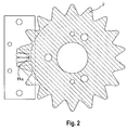
- the object is achieved by one, one rotating disc with periodic edge shape, with the wave above and below of the torsion element is connected and in a region of the periodic Edge shape of the outer edge of the panes of a lighting device can be illuminated, one consisting of several sensors Sensor unit for determining the degree of illumination under each pane edge is attached and at the same time a phase angle of the respective edge structure Sensor device determines and the difference in the angle of rotation of the disks to each other is determined.
- the advantage of the invention is that there are no electrical parts on the shaft are arranged.
- the torsion washers are rigid and therefore resistant to vibrations arranged, which is of particular importance for use in the motor vehicle, since an exact measurement result is thereby achieved.
- the sensors are arranged over the length of an edge period, whereby the difference signal can be easily evaluated
- a multi-channel evaluation of the measurement signal is easily possible if as sensors four photodiodes are arranged over the length of an edge period, whereby the output signals of two photodiodes always form a differential signal. The usage two such diode pairs form a redundant system.
- the measuring arrangement is advantageously also possible with three photodiodes, which are also distributed over the length of a marginal period.
- the measuring section is extended along the edge contour of the discs n sensors arranged.
- the calibration of the measuring channels takes place via a calibration device which is connected to the Is connected to photodiodes and which in a given period of time individual measuring channels occurring maximum and minimum values detected and from it determined a calibration value.
- a control device which for Plausibility check the currently determined difference between the phase angles of the compares the two disks with a previously determined difference.
- read-out devices that include a Enable reading of the individual measuring channels simultaneously.
- a torque sensor 1 is on a steering column 2 of a motor vehicle, which is shown here only in sections. Between the steering wheel and steering gear is a torsion element 4 with a measuring shaft 5 arranged. When the steering column 2 from the steering wheel with a torque is applied, then the measuring shaft 5 twists.
- Each sensor device has a disk 7 or 8, each one Lighting device 6 or 10 is assigned.
- the lighting device is arranged so that their beam direction is perpendicular to the radial extent the disc 7 or 8 runs.
- the lighting device 6 or 10 the outer edge of the disc 7 and 8 illuminated.
- the lighting devices 6 and 10 are together with photodiodes 11a and 11b on a holder 9 attached.
- the photodiodes 11a and 11b are arranged so that they emitted by a lighting device 6 or 10 and from the pane Detect interrupted beam.
- the disc 7 is between the lighting device 6 and photodiodes 11a arranged while the disc 8 between the lighting device 10 and the photodiodes 11b.
- the disc 8 is connected to the shaft 5 of the torsion element 4, while the disc 7 outside the shaft 5 is attached to the torsion elements 4.
- the outer edge of the discs 7, 8 is provided with a circumferential periodic edge shape.
- a statement is made regarding the position of the disks 7, 8 with respect to the fixed photodiodes.
- the difference in the angles of rotation of the disks 7, 8 with respect to one another is determined.
- a phase angle of the respective edge structure to the sensor device is determined at the same time.
- the arrangement with four sensors is selected as an example.
- a brightness distribution is assumed which fluctuates in the ⁇ direction according to a harmonic function with the period length 2 ⁇ .
- this brightness distribution is represented by a more or less strong covering of the otherwise uniformly illuminated sensor surfaces by the edge of the pane above.
- Eq. 2 S2 k + Asin ( ⁇ + 1 ⁇ 2 ⁇ )
- Eq. 3 S3 k + Asin ( ⁇ + ⁇ )
- Eq.4 S4 k + Asin ( ⁇ + 3/2 ⁇ )
- K is the center around which the signal oscillates.
- K is a constant DC component of the signal voltages and
- A is the amplitude with which the signal voltages when the arrangement is shifted from the brightness distribution or edge shape vary.
- the signals S5 and S8 are determined for the second sensor arrangement and offset.
- phase angle there may be jumps in the calculated values if one or the other disk passes over the end or the beginning of its own period.
- a control must be provided in the data processing that recognizes such a jump as nonsensical and uses suitable measures to calculate it.
- Such a check can be carried out based on the present invention by comparing the current calculated value for the difference between the phase angles of the two slices with the previous value. If the difference is less than - ⁇ , 2 ⁇ is added for correction, if the difference is greater than + ⁇ , subtraction of 2 ⁇ is made for correction.
- the measurements to be carried out can cause disturbing noise in the measuring channels.
- a continuous averaging is used to smooth the channels, which does not interfere with the function of the device at a sufficiently high readout frequency. For example, the last twenty values are saved. With each new value, the older value falls out of the calculation.
- the individual measuring channels are read out at the same time, since a time delay could falsify the measured value.
Landscapes
- Physics & Mathematics (AREA)
- General Physics & Mathematics (AREA)
- Length Measuring Devices By Optical Means (AREA)
- Force Measurement Appropriate To Specific Purposes (AREA)
Applications Claiming Priority (2)
| Application Number | Priority Date | Filing Date | Title |
|---|---|---|---|
| DE19962525 | 1999-12-23 | ||
| DE19962525A DE19962525B4 (de) | 1999-12-23 | 1999-12-23 | Optischer Drehmomentesensor |
Publications (2)
| Publication Number | Publication Date |
|---|---|
| EP1111358A2 true EP1111358A2 (fr) | 2001-06-27 |
| EP1111358A3 EP1111358A3 (fr) | 2002-07-31 |
Family
ID=7934169
Family Applications (1)
| Application Number | Title | Priority Date | Filing Date |
|---|---|---|---|
| EP00126913A Withdrawn EP1111358A3 (fr) | 1999-12-23 | 2000-12-08 | Capteur de couple optique |
Country Status (2)
| Country | Link |
|---|---|
| EP (1) | EP1111358A3 (fr) |
| DE (1) | DE19962525B4 (fr) |
Cited By (2)
| Publication number | Priority date | Publication date | Assignee | Title |
|---|---|---|---|---|
| US6888639B2 (en) | 2001-09-24 | 2005-05-03 | Applied Materials, Inc. | In-situ film thickness measurement using spectral interference at grazing incidence |
| US10088338B2 (en) | 2014-07-28 | 2018-10-02 | Halliburton Energy Services, Inc. | Optical shaft twist angle measurement methods and systems |
Families Citing this family (1)
| Publication number | Priority date | Publication date | Assignee | Title |
|---|---|---|---|---|
| DE102009022712A1 (de) | 2009-05-26 | 2010-12-02 | Bourns, Inc., Riverside | Torsionswinkelsensor |
Family Cites Families (19)
| Publication number | Priority date | Publication date | Assignee | Title |
|---|---|---|---|---|
| CH334363A (de) * | 1953-11-04 | 1958-11-30 | Ici Ltd | Vorrichtung zum Messen der Grösse der Verdrehung einer Welle |
| GB946140A (en) * | 1961-05-04 | 1964-01-08 | Ford Motor Co | Improvements in or relating to torquemeters |
| DE1216572B (de) * | 1962-02-08 | 1966-05-12 | Escher Wyss Ag | Verfahren und Vorrichtung zur Messung der Verdrehung eines Wellenstueckes waehrend dessen Umlauf |
| DE1224956B (de) * | 1964-04-15 | 1966-09-15 | Versuchsanstalt Fuer Luft Und | Anordnung zur Messung der Verdrehung rotierender Wellen |
| DE2811809C2 (de) * | 1978-03-16 | 1980-04-17 | Mannesmann Ag, 4000 Duesseldorf | Meßumformer zum Messen von Verdrehwinkeln zwischen zwei Meßstellen eines ein Drehmoment übertragenden Maschinenelementes |
| DE2928155A1 (de) * | 1979-07-12 | 1981-01-29 | Licentia Gmbh | Messanordnung |
| GB2116313B (en) * | 1982-02-25 | 1985-09-04 | Ferranti Plc | Sine wave generator for position encoder |
| DE3637318A1 (de) * | 1986-11-03 | 1988-05-11 | Stabil Elektronik Gmbh | Vorrichtung zum messen der lastabhaengigen verdrillung einer rotierenden welle |
| KR890000890A (ko) * | 1987-06-22 | 1989-03-17 | 미타 가츠시게 | 토크검출장치 |
| DE3873257D1 (de) * | 1987-10-28 | 1992-09-03 | Rohs Ulrich | Vorrichtung zur messung des drehmomentes einer arbeitswelle. |
| JPH01196515A (ja) * | 1988-02-01 | 1989-08-08 | Fuji Electric Co Ltd | 光電変換式回転位置検出器 |
| GB9202868D0 (en) * | 1992-02-12 | 1992-03-25 | Lucas Ind Plc | Optical torque sensors and steering systems for vehicles incorporating them |
| US5625239A (en) * | 1992-06-03 | 1997-04-29 | Trw Inc. | Method and apparatus for sensing relative position between two relatively rotatable members using concentric rings |
| NO300940B1 (no) * | 1994-09-26 | 1997-08-18 | Frantz Karsten Smith | Anordning for maling av torsjon pa roterende akslinger |
| IT239204Y1 (it) * | 1995-10-20 | 2001-02-19 | Paolo Codazzi | Sistema di misura a collimazione a fascio singolo del momento torcentedella velocita' angolare e del senso di rotazione di assi rotanti |
| JPH1081158A (ja) * | 1996-06-05 | 1998-03-31 | Luk Getriebe Syst Gmbh | 自動車 |
| US5763793A (en) * | 1997-01-16 | 1998-06-09 | Methode Electronics, Inc. | Error correcting torque sensor |
| DE19745823A1 (de) * | 1997-10-16 | 1999-04-29 | Sensor Instr Gmbh | Vorrichtung zum gleichzeitigen Messen von Drehmoment und Drehwinkel |
| AUPP098497A0 (en) * | 1997-12-17 | 1998-01-15 | Bishop Innovation Pty Limited | Transmission path torque transducer |
-
1999
- 1999-12-23 DE DE19962525A patent/DE19962525B4/de not_active Expired - Fee Related
-
2000
- 2000-12-08 EP EP00126913A patent/EP1111358A3/fr not_active Withdrawn
Cited By (2)
| Publication number | Priority date | Publication date | Assignee | Title |
|---|---|---|---|---|
| US6888639B2 (en) | 2001-09-24 | 2005-05-03 | Applied Materials, Inc. | In-situ film thickness measurement using spectral interference at grazing incidence |
| US10088338B2 (en) | 2014-07-28 | 2018-10-02 | Halliburton Energy Services, Inc. | Optical shaft twist angle measurement methods and systems |
Also Published As
| Publication number | Publication date |
|---|---|
| EP1111358A3 (fr) | 2002-07-31 |
| DE19962525A1 (de) | 2001-07-05 |
| DE19962525B4 (de) | 2013-11-21 |
Similar Documents
| Publication | Publication Date | Title |
|---|---|---|
| DE68917191T2 (de) | Gerät zur Drehmomentdetektion mit Fehlersignal. | |
| DE10041095B4 (de) | Vorrichtung zur Messung eines Winkels und/oder eines Drehmomentes eines drehbaren Körpers | |
| EP2420803A1 (fr) | Dispositif de saisie de l'angle de distorsion d'un arbre et/ou d'un couple situé sur l'arbre et procédé de fonctionnement du dispositif | |
| DE10158223B4 (de) | Drehwinkel-Messgerät | |
| DE3821083C2 (fr) | ||
| DE102008043556B4 (de) | Positionsmesseinrichtung | |
| WO2005068962A1 (fr) | Dispositif pour determiner un angle de braquage et un couple de rotation exerce sur un arbre de direction | |
| DE69902209T2 (de) | Kombinierter drehmoment-inkremental-geber | |
| EP1238251A1 (fr) | Dispositif pour mesurer un angle et/ou la vitesse angulaire d'un corps rotatif et/ou le couple de rotation applique a ce dernier | |
| EP0276402B1 (fr) | Codeur de position angulaire de grande précision avec détection fotoélectrique | |
| EP1923670B1 (fr) | Dispositif de mesure de position | |
| EP0143354B1 (fr) | Codeur d'angle à plusieurs étages | |
| EP1313638B1 (fr) | Procede d'auto-etalonnage d'un angle de torsion mesure par un dispositif de mesure de couple et d'angle | |
| DE102004023801A1 (de) | Vorrichtung zum Bestimmen eines Lenkwinkels und eines an einer Lenkwelle ausgeübten Drehmoments | |
| DE102013224098A1 (de) | Sensoranordnung zur Erfassung von Drehwinkeln an einem rotierenden Bauteil in einem Fahrzeug | |
| DE10020980B4 (de) | Schritt-Drehcodierer und Vermessungsinstrument mit einem Schritt-Drehcodierer | |
| DE3911873A1 (de) | Vorrichtung und verfahren zum einstellen der hoehe eines fahrzeugs | |
| DE19626654C2 (de) | Multiturn-Drehgeber | |
| DE69427326T2 (de) | Verbesserte Positionssignale in optischen Drehmomentsensoren | |
| DE102005021300A1 (de) | Drehgeber | |
| EP1111358A2 (fr) | Capteur de couple optique | |
| EP3760980B1 (fr) | Dispositif de mesure d'angle | |
| EP3760981B1 (fr) | Dispositif de mesure d'angle et procédé de fonctionnement d'un dispositif de mesure d'angle | |
| EP2673594B1 (fr) | Procédé d'enregistrement de l'angle de torsion d'un arbre et/ou d'un moment de rotation généré sur l'arbre et mise en uvre du procédé | |
| EP1511973B1 (fr) | Procede et ensemble de detection du mouvement d'un element |
Legal Events
| Date | Code | Title | Description |
|---|---|---|---|
| PUAI | Public reference made under article 153(3) epc to a published international application that has entered the european phase |
Free format text: ORIGINAL CODE: 0009012 |
|
| AK | Designated contracting states |
Kind code of ref document: A2 Designated state(s): AT BE CH CY DE DK ES FI FR GB GR IE IT LI LU MC NL PT SE TR |
|
| AX | Request for extension of the european patent |
Free format text: AL;LT;LV;MK;RO;SI |
|
| RAP1 | Party data changed (applicant data changed or rights of an application transferred) |
Owner name: SIEMENS AKTIENGESELLSCHAFT |
|
| PUAL | Search report despatched |
Free format text: ORIGINAL CODE: 0009013 |
|
| AK | Designated contracting states |
Kind code of ref document: A3 Designated state(s): AT BE CH CY DE DK ES FI FR GB GR IE IT LI LU MC NL PT SE TR |
|
| AX | Request for extension of the european patent |
Free format text: AL;LT;LV;MK;RO;SI |
|
| RIC1 | Information provided on ipc code assigned before grant |
Free format text: 7G 01L 3/12 A, 7B 62D 5/04 B |
|
| 17P | Request for examination filed |
Effective date: 20020819 |
|
| AKX | Designation fees paid |
Designated state(s): DE FR GB |
|
| STAA | Information on the status of an ep patent application or granted ep patent |
Free format text: STATUS: THE APPLICATION IS DEEMED TO BE WITHDRAWN |
|
| 18D | Application deemed to be withdrawn |
Effective date: 20040701 |