EP1112140B1 - Source de rayonnement laser - Google Patents
Source de rayonnement laser Download PDFInfo
- Publication number
- EP1112140B1 EP1112140B1 EP99953638A EP99953638A EP1112140B1 EP 1112140 B1 EP1112140 B1 EP 1112140B1 EP 99953638 A EP99953638 A EP 99953638A EP 99953638 A EP99953638 A EP 99953638A EP 1112140 B1 EP1112140 B1 EP 1112140B1
- Authority
- EP
- European Patent Office
- Prior art keywords
- laser
- fiber
- radiation source
- lasers
- laser radiation
- Prior art date
- Legal status (The legal status is an assumption and is not a legal conclusion. Google has not performed a legal analysis and makes no representation as to the accuracy of the status listed.)
- Expired - Lifetime
Links
Images













Classifications
-
- B—PERFORMING OPERATIONS; TRANSPORTING
- B41—PRINTING; LINING MACHINES; TYPEWRITERS; STAMPS
- B41C—PROCESSES FOR THE MANUFACTURE OR REPRODUCTION OF PRINTING SURFACES
- B41C1/00—Forme preparation
- B41C1/02—Engraving; Heads therefor
- B41C1/04—Engraving; Heads therefor using heads controlled by an electric information signal
- B41C1/05—Heat-generating engraving heads, e.g. laser beam, electron beam
-
- B—PERFORMING OPERATIONS; TRANSPORTING
- B23—MACHINE TOOLS; METAL-WORKING NOT OTHERWISE PROVIDED FOR
- B23K—SOLDERING OR UNSOLDERING; WELDING; CLADDING OR PLATING BY SOLDERING OR WELDING; CUTTING BY APPLYING HEAT LOCALLY, e.g. FLAME CUTTING; WORKING BY LASER BEAM
- B23K26/00—Working by laser beam, e.g. welding, cutting or boring
- B23K26/02—Positioning or observing the workpiece, e.g. with respect to the point of impact; Aligning, aiming or focusing the laser beam
- B23K26/06—Shaping the laser beam, e.g. by masks or multi-focusing
- B23K26/0604—Shaping the laser beam, e.g. by masks or multi-focusing by a combination of beams
-
- B—PERFORMING OPERATIONS; TRANSPORTING
- B23—MACHINE TOOLS; METAL-WORKING NOT OTHERWISE PROVIDED FOR
- B23K—SOLDERING OR UNSOLDERING; WELDING; CLADDING OR PLATING BY SOLDERING OR WELDING; CUTTING BY APPLYING HEAT LOCALLY, e.g. FLAME CUTTING; WORKING BY LASER BEAM
- B23K26/00—Working by laser beam, e.g. welding, cutting or boring
- B23K26/02—Positioning or observing the workpiece, e.g. with respect to the point of impact; Aligning, aiming or focusing the laser beam
- B23K26/06—Shaping the laser beam, e.g. by masks or multi-focusing
- B23K26/0604—Shaping the laser beam, e.g. by masks or multi-focusing by a combination of beams
- B23K26/0608—Shaping the laser beam, e.g. by masks or multi-focusing by a combination of beams in the same heat affected zone [HAZ]
-
- B—PERFORMING OPERATIONS; TRANSPORTING
- B23—MACHINE TOOLS; METAL-WORKING NOT OTHERWISE PROVIDED FOR
- B23K—SOLDERING OR UNSOLDERING; WELDING; CLADDING OR PLATING BY SOLDERING OR WELDING; CUTTING BY APPLYING HEAT LOCALLY, e.g. FLAME CUTTING; WORKING BY LASER BEAM
- B23K26/00—Working by laser beam, e.g. welding, cutting or boring
- B23K26/02—Positioning or observing the workpiece, e.g. with respect to the point of impact; Aligning, aiming or focusing the laser beam
- B23K26/06—Shaping the laser beam, e.g. by masks or multi-focusing
- B23K26/0604—Shaping the laser beam, e.g. by masks or multi-focusing by a combination of beams
- B23K26/0613—Shaping the laser beam, e.g. by masks or multi-focusing by a combination of beams having a common axis
-
- B—PERFORMING OPERATIONS; TRANSPORTING
- B23—MACHINE TOOLS; METAL-WORKING NOT OTHERWISE PROVIDED FOR
- B23K—SOLDERING OR UNSOLDERING; WELDING; CLADDING OR PLATING BY SOLDERING OR WELDING; CUTTING BY APPLYING HEAT LOCALLY, e.g. FLAME CUTTING; WORKING BY LASER BEAM
- B23K26/00—Working by laser beam, e.g. welding, cutting or boring
- B23K26/02—Positioning or observing the workpiece, e.g. with respect to the point of impact; Aligning, aiming or focusing the laser beam
- B23K26/06—Shaping the laser beam, e.g. by masks or multi-focusing
- B23K26/062—Shaping the laser beam, e.g. by masks or multi-focusing by direct control of the laser beam
- B23K26/0622—Shaping the laser beam, e.g. by masks or multi-focusing by direct control of the laser beam by shaping pulses
-
- B—PERFORMING OPERATIONS; TRANSPORTING
- B23—MACHINE TOOLS; METAL-WORKING NOT OTHERWISE PROVIDED FOR
- B23K—SOLDERING OR UNSOLDERING; WELDING; CLADDING OR PLATING BY SOLDERING OR WELDING; CUTTING BY APPLYING HEAT LOCALLY, e.g. FLAME CUTTING; WORKING BY LASER BEAM
- B23K26/00—Working by laser beam, e.g. welding, cutting or boring
- B23K26/02—Positioning or observing the workpiece, e.g. with respect to the point of impact; Aligning, aiming or focusing the laser beam
- B23K26/06—Shaping the laser beam, e.g. by masks or multi-focusing
- B23K26/064—Shaping the laser beam, e.g. by masks or multi-focusing by means of optical elements, e.g. lenses, mirrors or prisms
-
- B—PERFORMING OPERATIONS; TRANSPORTING
- B23—MACHINE TOOLS; METAL-WORKING NOT OTHERWISE PROVIDED FOR
- B23K—SOLDERING OR UNSOLDERING; WELDING; CLADDING OR PLATING BY SOLDERING OR WELDING; CUTTING BY APPLYING HEAT LOCALLY, e.g. FLAME CUTTING; WORKING BY LASER BEAM
- B23K26/00—Working by laser beam, e.g. welding, cutting or boring
- B23K26/02—Positioning or observing the workpiece, e.g. with respect to the point of impact; Aligning, aiming or focusing the laser beam
- B23K26/06—Shaping the laser beam, e.g. by masks or multi-focusing
- B23K26/064—Shaping the laser beam, e.g. by masks or multi-focusing by means of optical elements, e.g. lenses, mirrors or prisms
- B23K26/0643—Shaping the laser beam, e.g. by masks or multi-focusing by means of optical elements, e.g. lenses, mirrors or prisms comprising mirrors
-
- B—PERFORMING OPERATIONS; TRANSPORTING
- B23—MACHINE TOOLS; METAL-WORKING NOT OTHERWISE PROVIDED FOR
- B23K—SOLDERING OR UNSOLDERING; WELDING; CLADDING OR PLATING BY SOLDERING OR WELDING; CUTTING BY APPLYING HEAT LOCALLY, e.g. FLAME CUTTING; WORKING BY LASER BEAM
- B23K26/00—Working by laser beam, e.g. welding, cutting or boring
- B23K26/02—Positioning or observing the workpiece, e.g. with respect to the point of impact; Aligning, aiming or focusing the laser beam
- B23K26/06—Shaping the laser beam, e.g. by masks or multi-focusing
- B23K26/064—Shaping the laser beam, e.g. by masks or multi-focusing by means of optical elements, e.g. lenses, mirrors or prisms
- B23K26/0648—Shaping the laser beam, e.g. by masks or multi-focusing by means of optical elements, e.g. lenses, mirrors or prisms comprising lenses
-
- B—PERFORMING OPERATIONS; TRANSPORTING
- B23—MACHINE TOOLS; METAL-WORKING NOT OTHERWISE PROVIDED FOR
- B23K—SOLDERING OR UNSOLDERING; WELDING; CLADDING OR PLATING BY SOLDERING OR WELDING; CUTTING BY APPLYING HEAT LOCALLY, e.g. FLAME CUTTING; WORKING BY LASER BEAM
- B23K26/00—Working by laser beam, e.g. welding, cutting or boring
- B23K26/02—Positioning or observing the workpiece, e.g. with respect to the point of impact; Aligning, aiming or focusing the laser beam
- B23K26/06—Shaping the laser beam, e.g. by masks or multi-focusing
- B23K26/064—Shaping the laser beam, e.g. by masks or multi-focusing by means of optical elements, e.g. lenses, mirrors or prisms
- B23K26/0652—Shaping the laser beam, e.g. by masks or multi-focusing by means of optical elements, e.g. lenses, mirrors or prisms comprising prisms
-
- B—PERFORMING OPERATIONS; TRANSPORTING
- B23—MACHINE TOOLS; METAL-WORKING NOT OTHERWISE PROVIDED FOR
- B23K—SOLDERING OR UNSOLDERING; WELDING; CLADDING OR PLATING BY SOLDERING OR WELDING; CUTTING BY APPLYING HEAT LOCALLY, e.g. FLAME CUTTING; WORKING BY LASER BEAM
- B23K26/00—Working by laser beam, e.g. welding, cutting or boring
- B23K26/02—Positioning or observing the workpiece, e.g. with respect to the point of impact; Aligning, aiming or focusing the laser beam
- B23K26/06—Shaping the laser beam, e.g. by masks or multi-focusing
- B23K26/0665—Shaping the laser beam, e.g. by masks or multi-focusing by beam condensation on the workpiece, e.g. for focusing
-
- B—PERFORMING OPERATIONS; TRANSPORTING
- B23—MACHINE TOOLS; METAL-WORKING NOT OTHERWISE PROVIDED FOR
- B23K—SOLDERING OR UNSOLDERING; WELDING; CLADDING OR PLATING BY SOLDERING OR WELDING; CUTTING BY APPLYING HEAT LOCALLY, e.g. FLAME CUTTING; WORKING BY LASER BEAM
- B23K26/00—Working by laser beam, e.g. welding, cutting or boring
- B23K26/02—Positioning or observing the workpiece, e.g. with respect to the point of impact; Aligning, aiming or focusing the laser beam
- B23K26/06—Shaping the laser beam, e.g. by masks or multi-focusing
- B23K26/067—Dividing the beam into multiple beams, e.g. multi-focusing
-
- B—PERFORMING OPERATIONS; TRANSPORTING
- B23—MACHINE TOOLS; METAL-WORKING NOT OTHERWISE PROVIDED FOR
- B23K—SOLDERING OR UNSOLDERING; WELDING; CLADDING OR PLATING BY SOLDERING OR WELDING; CUTTING BY APPLYING HEAT LOCALLY, e.g. FLAME CUTTING; WORKING BY LASER BEAM
- B23K26/00—Working by laser beam, e.g. welding, cutting or boring
- B23K26/02—Positioning or observing the workpiece, e.g. with respect to the point of impact; Aligning, aiming or focusing the laser beam
- B23K26/06—Shaping the laser beam, e.g. by masks or multi-focusing
- B23K26/067—Dividing the beam into multiple beams, e.g. multi-focusing
- B23K26/0676—Dividing the beam into multiple beams, e.g. multi-focusing into dependently operating sub-beams, e.g. an array of spots with fixed spatial relationship or for performing simultaneously identical operations
-
- B—PERFORMING OPERATIONS; TRANSPORTING
- B23—MACHINE TOOLS; METAL-WORKING NOT OTHERWISE PROVIDED FOR
- B23K—SOLDERING OR UNSOLDERING; WELDING; CLADDING OR PLATING BY SOLDERING OR WELDING; CUTTING BY APPLYING HEAT LOCALLY, e.g. FLAME CUTTING; WORKING BY LASER BEAM
- B23K26/00—Working by laser beam, e.g. welding, cutting or boring
- B23K26/08—Devices involving relative movement between laser beam and workpiece
- B23K26/082—Scanning systems, i.e. devices involving movement of the laser beam relative to the laser head
-
- B—PERFORMING OPERATIONS; TRANSPORTING
- B23—MACHINE TOOLS; METAL-WORKING NOT OTHERWISE PROVIDED FOR
- B23K—SOLDERING OR UNSOLDERING; WELDING; CLADDING OR PLATING BY SOLDERING OR WELDING; CUTTING BY APPLYING HEAT LOCALLY, e.g. FLAME CUTTING; WORKING BY LASER BEAM
- B23K26/00—Working by laser beam, e.g. welding, cutting or boring
- B23K26/08—Devices involving relative movement between laser beam and workpiece
- B23K26/083—Devices involving movement of the workpiece in at least one axial direction
- B23K26/0853—Devices involving movement of the workpiece in at least two axial directions, e.g. in a plane
- B23K26/0861—Devices involving movement of the workpiece in at least two axial directions, e.g. in a plane in at least three axial directions
-
- B—PERFORMING OPERATIONS; TRANSPORTING
- B23—MACHINE TOOLS; METAL-WORKING NOT OTHERWISE PROVIDED FOR
- B23K—SOLDERING OR UNSOLDERING; WELDING; CLADDING OR PLATING BY SOLDERING OR WELDING; CUTTING BY APPLYING HEAT LOCALLY, e.g. FLAME CUTTING; WORKING BY LASER BEAM
- B23K26/00—Working by laser beam, e.g. welding, cutting or boring
- B23K26/08—Devices involving relative movement between laser beam and workpiece
- B23K26/0869—Devices involving movement of the laser head in at least one axial direction
- B23K26/0876—Devices involving movement of the laser head in at least one axial direction in at least two axial directions
- B23K26/0884—Devices involving movement of the laser head in at least one axial direction in at least two axial directions in at least three axial directions, e.g. manipulators, robots
-
- B—PERFORMING OPERATIONS; TRANSPORTING
- B23—MACHINE TOOLS; METAL-WORKING NOT OTHERWISE PROVIDED FOR
- B23K—SOLDERING OR UNSOLDERING; WELDING; CLADDING OR PLATING BY SOLDERING OR WELDING; CUTTING BY APPLYING HEAT LOCALLY, e.g. FLAME CUTTING; WORKING BY LASER BEAM
- B23K26/00—Working by laser beam, e.g. welding, cutting or boring
- B23K26/14—Working by laser beam, e.g. welding, cutting or boring using a fluid stream, e.g. a jet of gas, in conjunction with the laser beam; Nozzles therefor
- B23K26/142—Working by laser beam, e.g. welding, cutting or boring using a fluid stream, e.g. a jet of gas, in conjunction with the laser beam; Nozzles therefor for the removal of by-products
-
- B—PERFORMING OPERATIONS; TRANSPORTING
- B23—MACHINE TOOLS; METAL-WORKING NOT OTHERWISE PROVIDED FOR
- B23K—SOLDERING OR UNSOLDERING; WELDING; CLADDING OR PLATING BY SOLDERING OR WELDING; CUTTING BY APPLYING HEAT LOCALLY, e.g. FLAME CUTTING; WORKING BY LASER BEAM
- B23K26/00—Working by laser beam, e.g. welding, cutting or boring
- B23K26/14—Working by laser beam, e.g. welding, cutting or boring using a fluid stream, e.g. a jet of gas, in conjunction with the laser beam; Nozzles therefor
- B23K26/1462—Nozzles; Features related to nozzles
-
- B—PERFORMING OPERATIONS; TRANSPORTING
- B23—MACHINE TOOLS; METAL-WORKING NOT OTHERWISE PROVIDED FOR
- B23K—SOLDERING OR UNSOLDERING; WELDING; CLADDING OR PLATING BY SOLDERING OR WELDING; CUTTING BY APPLYING HEAT LOCALLY, e.g. FLAME CUTTING; WORKING BY LASER BEAM
- B23K26/00—Working by laser beam, e.g. welding, cutting or boring
- B23K26/36—Removing material
- B23K26/38—Removing material by boring or cutting
- B23K26/382—Removing material by boring or cutting by boring
-
- B—PERFORMING OPERATIONS; TRANSPORTING
- B23—MACHINE TOOLS; METAL-WORKING NOT OTHERWISE PROVIDED FOR
- B23K—SOLDERING OR UNSOLDERING; WELDING; CLADDING OR PLATING BY SOLDERING OR WELDING; CUTTING BY APPLYING HEAT LOCALLY, e.g. FLAME CUTTING; WORKING BY LASER BEAM
- B23K26/00—Working by laser beam, e.g. welding, cutting or boring
- B23K26/36—Removing material
- B23K26/38—Removing material by boring or cutting
- B23K26/382—Removing material by boring or cutting by boring
- B23K26/389—Removing material by boring or cutting by boring of fluid openings, e.g. nozzles, jets
-
- B—PERFORMING OPERATIONS; TRANSPORTING
- B23—MACHINE TOOLS; METAL-WORKING NOT OTHERWISE PROVIDED FOR
- B23K—SOLDERING OR UNSOLDERING; WELDING; CLADDING OR PLATING BY SOLDERING OR WELDING; CUTTING BY APPLYING HEAT LOCALLY, e.g. FLAME CUTTING; WORKING BY LASER BEAM
- B23K26/00—Working by laser beam, e.g. welding, cutting or boring
- B23K26/36—Removing material
- B23K26/40—Removing material taking account of the properties of the material involved
-
- B—PERFORMING OPERATIONS; TRANSPORTING
- B23—MACHINE TOOLS; METAL-WORKING NOT OTHERWISE PROVIDED FOR
- B23K—SOLDERING OR UNSOLDERING; WELDING; CLADDING OR PLATING BY SOLDERING OR WELDING; CUTTING BY APPLYING HEAT LOCALLY, e.g. FLAME CUTTING; WORKING BY LASER BEAM
- B23K2101/00—Articles made by soldering, welding or cutting
- B23K2101/36—Electric or electronic devices
- B23K2101/40—Semiconductor devices
-
- B—PERFORMING OPERATIONS; TRANSPORTING
- B23—MACHINE TOOLS; METAL-WORKING NOT OTHERWISE PROVIDED FOR
- B23K—SOLDERING OR UNSOLDERING; WELDING; CLADDING OR PLATING BY SOLDERING OR WELDING; CUTTING BY APPLYING HEAT LOCALLY, e.g. FLAME CUTTING; WORKING BY LASER BEAM
- B23K2103/00—Materials to be soldered, welded or cut
- B23K2103/50—Inorganic materials other than metals or composite materials
Definitions
- the invention relates to a laser radiation source of high power density and high energy for material processing, as well as an arrangement for material processing with such a laser radiation source.
- a typical case in which extremely fine structures must be produced on a processing surface is the production of printing forms, be it for gravure, offset, high-pressure, screen printing or flexographic printing or for other printing processes.
- printing forms be it for gravure, offset, high-pressure, screen printing or flexographic printing or for other printing processes.
- it is necessary to produce extremely fine structures on the surface of the printing plates since the surface of the printing forms is intended to reproduce high-resolution image information such as text, raster images, graphics and linework.
- a long service life is required at high print runs, eg in particular magazine impression or packaging printing, since during the printing process, the surface of the printing form wears as a result of the action of the doctor blade and the printing material.
- the printing cylinders are provided with a galvanized copper layer, or else solid cylinders made of copper are used.
- Another way to extend the life even more is that the copper surface is electroplated chrome after engraving.
- the so-called "hot chrome plating" is used in addition, in which the galvanic Process under elevated temperature expires.
- the longest achievable service life can be achieved.
- copper is the most suitable material for the surface of gravure cylinders. Other materials than copper have not been proven for long runs.
- the diamond stylus When producing the cups, the diamond stylus is driven by an electromechanically driven magnet system with an oscillating armature on which the diamond stylus is mounted.
- an electromechanical oscillation system can not be made arbitrarily fast because of the forces required to engrave the wells.
- This magnet system is therefore operated above its resonant frequency so that the highest engraving frequency, i. the highest engraving speed can be achieved.
- several such engraving systems have been arranged side by side in the axial direction of the copper cylinder in today's engraving machines. However, this still does not suffice for the short engraving time of the printing cylinders required today, since the engraving time directly influences the actuality of the printing result. For this reason, gravure engraving is not used for newspaper printing, but primarily for the magazine impression.
- the well volume is varied depending on the image content of the original to be printed.
- the respective tone value of the original should be reproduced as accurately as possible during printing.
- analogue / digital converters for example with a resolution of 12 bits, are used to detect the tone levels for reasons of image signal processing (eg gradation settings), which in this case corresponds to a resolution in 4096 tonal values. From this high-resolution image information, the signal for driving the electromagnetic engraving system is obtained, which is usually an 8-bit signal, which corresponds to a resolution in 256 tone levels.
- the penetration depth of the diamond stylus into the copper surface is varied by driving the magnet system, the geometry of the wells being approximately between 120 .mu.m in diameter and 40 .mu.m in depth 30 microns diameter at a depth of 3 microns changes. Since only a very small range of variation in the depth of the wells between 40 microns and 3 microns is available, the penetration depth of the stylus, with which the wells are engraved, must be precisely controlled to fractions of microns in order to achieve the desired tonal range reproducible. As can be seen from this, an extremely high precision in the engraving of the wells is required, as far as the generation of the required diameters and depths of the wells is concerned.
- the geometry of the engraved well depends directly on the shape of the stylus, also very high demands are still on placed the geometry of the diamond stylus, which, as has been shown, can be achieved only with great effort and with much waste in the production of the stylus.
- the diamond stylus is subject to wear, as engraving a large printing cylinder with 14 strands, a circumference of 1.8 m and a length of 3.6 m at a grid of 70 lines / cm, which is a number of 4900 wells / cm 2 corresponds, about 20 million cells must be engraved by a stylus.
- the electromechanical engraving is well suited to produce high quality gravure cylinders, but it has a number of weak points and is very expensive and one would like to eliminate these disadvantages by another method.
- the cups thus produced which are later to receive the printing ink, are also arranged on the surface of the printing plate corresponding to a fine regular screen, namely the printing screen, wherein a separate printing cylinder is produced for each printing ink, and in each case a different screen with different angles and different screen ruling is used.
- a separate printing cylinder is produced for each printing ink, and in each case a different screen with different angles and different screen ruling is used.
- these grids remain between the individual wells narrow webs that carry the doctor blade in the printing press, which is the superfluous Coloring off after dyeing.
- Another disadvantage of the operation of this electro-mechanical engraving is that texts and lines must be rendered rasterized, which leads to Verreppieux the contours of the characters and the lines that recognizes the eye as disturbing.
- the laser power required for the engraving is transmitted to the cylinder surface via an optical fiber, the exit of which is imaged by a vario-focusing optics on the cylinder surface.
- a vario-focusing optics on the cylinder surface.
- a disadvantage of this method is that the required for pumping the laser arc lamps have a relatively short life and must be replaced after about 500 hours of operation. In the event of failure of the pumping light source during engraving, the engraving cylinder becomes unusable. This corresponds to a failure of the diamond stylus in electromechanical engraving and has the same disadvantages.
- a preventive replacement of the arc lamps is cost and labor intensive, especially since it is expected that the laser beam after replacement the lamps must be readjusted in its position.
- These lamp-pumped solid-state lasers also have a very poor efficiency, since the laser-active material only a small fraction of the energy offered from the pump source, ie here from the arc lamp, absorbed and converted into laser light.
- a major disadvantage of this method is that zinc is much softer than copper and is not suitable as a surface material for printing cylinder. Since the doctor blade, with which the excess ink is doctored off before printing in the printing press, is a steel knife, the zinc surface is damaged after a certain time and the printing cylinder becomes unusable. Therefore, a pressure cylinder having a surface of zinc does not reach nearly as long a press time as a printing cylinder having a surface of copper. Zinc surface printing plates are therefore not suitable for long runs.
- the zinc surface is chrome plated after engraving to increase tool life, the durability does not come close to normal copper cylinders. Chromium does not adhere well to zinc as well as to copper and the so-called "hot chrome plating" which is successfully used on copper cylinders achieving optimum adhesion of the chromium to the copper is not possible with zinc because it would melt the zinc. Since the chrome layer does not adhere very well to the zinc, it is also attacked by the doctor blade, resulting in a relatively early failure of the printing cylinder. On the other hand, if copper cylinders are chrome-plated according to this method, enormously high levels are possible because the chromium firmly adheres to the copper surface, so that these copper cylinders far exceed the chrome-plated zinc cylinders.
- the laser power is exactly constant and also remains constant over the entire time required for cylinder engraving. If this is not the case, the cup size changes and the cylinder becomes unusable. This can not be compensated by changing the size of the processing spot, since it is not possible to vary the processing spot sufficiently in shape.
- a low to moderate power laser radiation source having an optical unit for shaping the laser beam on a processing surface having a plurality of gallium arsenide lasers.
- the outputs of the lasers can be arranged side by side in several tracks.
- the laser beam emerging from each laser is passed through a fiber optic cable to the optical unit, which shapes the beam and focuses it onto the processing surface.
- the laser beams emerging from the optical unit can impinge side by side in a plurality of tracks on the processing surface.
- Phase-locked fiber lasers are already known, but they are very expensive to manufacture and are not suitable for industrial use.
- the laser beams emerging from the fiber lasers may there incident on an optical element, for example a lens, which bundles the laser beams as beams which intersect at a predetermined location.
- a laser system in which a low power master oscillator generates a primary laser signal at a particular wavelength.
- the primary laser signal is optically amplified in an amplifier having a similar structure as a fiber laser and is then split into a plurality of secondary laser signals which are also amplified with amplifiers.
- the amplified secondary laser signals may be merged with an optical unit of a plurality of lens elements to form a single higher power laser output beam.
- a plurality of electro-optical phase modulator elements is required for controllable adjustment of the respective phases of the secondary laser signals.
- a phase-locked laser system that discloses a plurality of diode-pumped fiber lasers with a portion of the outputs of the fiber lasers arranged side-by-side in multiple tracks.
- the object of the present invention is to improve a laser radiation source for material processing, as well as an arrangement for material processing with such a laser radiation source such that in a cost effective manner a very high power density and energy is achieved, and that both the beam shape in terms of flexibility, precision and beam positioning as Even the beam power can be precisely controlled even at much higher laser powers.
- This laser radiation source consists of several diode-pumped fiber lasers, also called fiber lasers whose output beams impinge on the processing site next to each other, and / or one above the other or in a point or bundle and thus the production of a shape and size selectively variable processing spot even at very high laser powers and extremely high power densities allows.
- These fiber lasers can be designed according to the invention as continuous wave lasers or Q-switched lasers, also called Q-switch lasers, wherein they are advantageously internally or externally modulated and / or have an additional modulator.
- Q-switch lasers have an optical modulator, such as an acousto-optic modulator, which, when open, interrupts the laser effect while the pump radiation is still present.
- energy is stored within the laser resonator, which is emitted when closing the modulator to a control signal out as a short laser pulse of high power.
- Q-switch lasers have the advantage that they emit short pulses of high power, resulting in a short time to a high power density. It is possible in pulsed operation by the short-term interruptions in the machining process, an advantageous discharge of the molten and vaporized material. Instead of switching the quality, it is also possible to generate a pulsed operation by means of internal or external modulation.
- the processing spot can be selectively changed in shape and size by different numbers of the lasers provided for shaping the processing spot can be turned on. It is particularly advantageous that the depth of the excavated cup regardless of its shape and size can be determined by the laser energy. Furthermore, by controlling the energy of the individual lasers, any desired beam profile can be generated within the machining spot and thus also any desired profile within the cell.
- the size of the processing spot is in the range of about 100 microns.
- a power density improved by a factor of 100 and a design possibility improved by a factor of 100 in the area of the machining spot are obtained.
- Due to the high precision and the very finely shaped processing spot can be very fine grid, u. a. also called the stochastic, also frequency-modulated grid (FM grid), produce and thus produce very smooth edges in lines and characters economically, so that the gravure printing offset printing in print quality will no longer be inferior.
- very fine grid u. a. also called the stochastic, also frequency-modulated grid (FM grid)
- FM grid frequency-modulated grid
- An advantage of the invention is that the differences in data preparation for the creation of the printing form between intaglio and offset print melt to a minimum, which entails considerable cost and Zeiterspamisse. So far, the data for the gravure printing from the already available for offset printing data obtained by conversion, because for the control of the engraving a signal is required, which determines the volume of a cup, wherein the area of a screen dot is determined in offset printing. With the help of the laser radiation source according to the invention, it is due to the Multiple arrangement of lasers makes it possible to vary the area of a well at a constant depth, so that it is no longer necessary to convert the data for offset printing into data for gravure printing. The data for offset printing can be used directly for engraving gravure forms.
- Another advantage of the invention is that with this laser radiation source, both the area of a cup and the depth can be controlled independently of each other, resulting in that a larger number of tone levels can be produced reproducibly, resulting in a more stable manufacturing process for the printing cylinder and results in a better print result.
- the energy can be easily transported by the fiber, namely the fiber laser itself, or a welded or otherwise coupled fiber from the pump source to the processing site, which is a particularly simple and space-saving design with it brings.
- Another advantage of the invention is that the efficiency of such a device with fiber lasers is much higher than the efficiency of solid state lasers, because for fiber lasers absorption efficiencies of over 60 percent are achieved, which are only about half of conventional diode pumped solid state lasers and in lamp-pumped solid state lasers are still far lower. With the required power of several kilowatts for efficient engraving of gravure cylinders, the efficiency of the lasers is of enormous importance for the equipment costs and the operating costs.
- the failure of a laser is less critical than with a single-channel arrangement. If, in the case of the single-channel arrangement, the only existing laser fails during the engraving of a printing cylinder, the entire printing cylinder is unusable. However, if a laser fails in a multiple arrangement, then one can slightly increase the power of the remaining lasers, for example, to compensate for the failure. After completing the engraving, the failed laser can be replaced.
- phase-locked fiber lasers have already been described, they are very expensive to manufacture and are not suitable for industrial use. It has hitherto not been recognized to bring lasers of this simple type in the proposed simple way to high power density and energy and to use for abrasive material processing.
- the resonator length of the individual lasers must be kept exactly constant to the fraction of a micrometre, for which so-called "piezoelectric fiber stretchers" are used. Due to the complex structure, it is likewise not possible to construct the laser unit in a modular fashion, that is to say, from components which are easy to assemble and multiply to be used, or to exchange individual laser components in the field as required. Also, due to the large number of optical components within a phase-locked laser, the optical losses are very high and the pumping radiation absorption of the laser-active medium is low, resulting in a low efficiency of the device.
- phase-locked lasers inherently have a high sensitivity to back reflections, ie if portions of the emitted radiation return to the laser resonator by reflection or scattering, as it is unavoidable in material processing. These back reflections lead to uncontrolled output amplitudes and can cause the laser to be exposed.
- so-called optical isolators are known to attenuate such back-reflections, but in practice bring a whole series of disadvantages, including, for example, the optical losses, the high price and the insufficient damping properties.
- the lasers for the purpose of material processing according to the invention not only have to have a high power density, but also can provide the required energy for lifting the wells, be very stable in the emitted radiation and have a very good efficiency.
- a laser system in which a master oscillator generates radiation energy of low power at a certain wavelength, which is optically amplified and distributed to further post-amplification on several post-amplifiers, and then reunited into a common beam, including a precise phase tracking of the Single amplified signals is required to avoid interference in the output signal.
- This requires complicated measuring and control operations and complex actuators, including, for example, electro-optical phase modulators must be used, which are very expensive and must be operated at very high voltages.
- a phase-coupled laser system indicated that uses a plurality of fibers or fiber cores in a bundle, the core must be both large compared to their coat or their distance in order to achieve the phase coupling, but on the other hand may only have a few microns in diameter, since it is Single-mode fibers.
- This system is mainly intended as an optical amplifier.
- phase-coupled laser system consisting of several so-called “sub-oscillators” is in the document GB-A-21 54 364 under the name “laser assemblies” already in the year 1984, but no industrial implementations have been known with such phase-locked laser systems.
- fiber lasers are their significantly lower tendency to oscillate when energy is returned to the laser.
- fiber lasers have an increase in resonance which is smaller by a magnitude in their transfer function, which has proven very positive in operation. Namely, in material processing, one can not always prevent energy from being reflected back into the laser from the processing site because the melting material is explosively thrown in unpredictable directions while flying through the laser beam, prior to any special measures taken in one embodiment of the invention, can be removed and rendered harmless.
- a significant advantage of the multiple arrangement of fiber lasers without phase coupling is that in the case of a return reflection, the individual lasers behave differently. This is related to the fact that, for example, some of the lasers are not affected by a return reflection at all, others possibly only with a delay. Therefore, there is a high probability that oscillations of the individual lasers, if they occur at all, will overlap so that they will not have a negative influence on the quality of the result of the engraving.
- the laser radiation source according to the invention can be used with advantage for all other types of material processing or material transfer, where it depends on high power density, high energy and high precision or high optical resolution.
- gravure cylinders with a copper surface other materials such.
- all metals, ceramics, glass, semiconductor materials, rubber or plastics are processed and / or materials are removed from specially prepared substrates and transferred to other materials at high speed and high precision.
- uncoated matte coated gravure cylinders, plates or cylinders, as well as all types of high speed, high resolution printing forms for offset, letterpress, flexo, and all other printing processes in addition to uncoated matte coated gravure cylinders, plates or cylinders, as well as all types of high speed, high resolution printing forms for offset, letterpress, flexo, and all other printing processes.
- the offset printing plates with metal coating (bimetallic plates) and similar materials used for the printing of very high runs in offset printing can also be imaged in an environmentally friendly manner, which was previously only possible by means of etching.
- the thus imaged material may serve as a master in conjunction with a corresponding toner.
- the application of the laser radiation source according to the invention is not limited to applications in printing technology, but it can be used wherever it is important to ablate with lasers at high resolution and high speed by energy irradiation material or to change its properties.
- the already mentioned texture rollers can also be produced with the laser radiation source according to the invention.
- the patterns of conductor tracks for printed circuit boards, including the bores for the components, preferably for multilayer printed circuit boards can be produced by removing the copper laminate and leaving the printed conductors and by removing copper laminate and carrier at the locations of the holes.
- material surfaces can be partially changed by partial heating in their surface structure.
- the laser beams can be guided in a variety of ways to the processing spot and directed over the material, for example, the material to be processed can be located on a rotating drum on which the radiation source is relatively moved past. But it may also be the material in a plane over which the laser radiation source or its output radiation are relatively passed.
- the material to be processed can be located on a rotating drum on which the radiation source is relatively moved past.
- it may also be the material in a plane over which the laser radiation source or its output radiation are relatively passed.
- a flat bed arrangement as described in the already mentioned document " The Laser in the Printing Industry "by W. Hülsbusch in Fig. 7- 28 on page 431 shown is and also in the publication EP-A-0 041 241 shown there as described in argon or He Ne laser or in Fig. 3 the publication as.
- the material to be processed may be located within a hollow cylinder over which the laser radiation source or its output radiation sweeps in a relative movement.
- Such an arrangement is from the document US-A-5,430,816 known.
- the exit of each fiber is then imaged onto the workpiece by means of a respective 60 mm diameter converging lens, whereby the distance between the individual processing points must be at least 60 mm and a protective device against contamination is required for each convergent lens.
- wafers which are usually circular discs of suitable semiconductor material, for example, scribed or cut or can be provided with all imaginable patterns in the surface, as they can be produced so far only by time-consuming and not environmentally friendly chemical etching processes.
- the laser radiation source is given in the manufacture of monitors and displays.
- the shadow masks for color screens, as well as the masks of the so-called flat screens or LCD displays can be produced more environmentally friendly with laser processing, than by the hitherto practiced chemical etching method by the laser radiation source according to the invention is applied.
- a significant advantage of the laser radiation source according to the invention is that it has a low volume and a flexible connection, namely the laser fibers or fibers connected thereto between the pump source and the outlet of the radiation at the processing location and thereby allows all conceivable operating positions of the laser radiation source or its radiation exit. Therefore, there are no restrictions on the spatial arrangement of the working surface, since they can be arranged in any position in space.
- Another advantage of the invention is that the beams of the individual lasers with defined values in beam diameter, beam divergence, centering and angular direction can be taken accurately and permanently in a terminator, creating a manufacturing and service-friendly arrangement for the transmission of laser radiation the working surface can be created.
- the beam may according to the invention, depending on the application z. B. coupled as a pump leak in the fiber and / or be coupled out as a parallel laser beam, diverge at the exit point or e.g. be focused at a certain distance from the exit point.
- optical fiber is taken in the final piece and the position of the optical fiber and / or the position of the exiting beam is precisely adjusted.
- a laser radiation source 1 which consists of several, according to the invention preferably as modules, diode-pumped fiber lasers (2), also called fiber laser, which are acted upon by a preferably modular supply 32 with electrical energy, which is largely converted into laser radiation. Furthermore, a controller 33 is provided, via which the modulation of the radiation is carried out and which ensures the interaction of the laser radiation source with its periphery.
- the output beams of the laser enter the radiation input 9 in an optical unit 8 and at the radiation output 10 from the optical unit.
- the task of the optical unit 8 is the shaping of the laser radiation to a processing spot 24 a processing surface 81, but it can also be the laser radiation without optical unit directed directly to the processing surface.
- a fiber laser arrangement (2) also called fiber laser arrangement
- the energy of a pump source such. B. a laser diode, here called pump source 18, formed via a coupling optics 3 to a suitable pump leak 4 and coupled into the laser fiber 5.
- pump sources are, for example, in the German patent application P 196 03 704 described by the applicant.
- Typical pumping cross sections of the laser fibers are approximately between 100 ⁇ m and 600 ⁇ m in diameter with a numerical aperture of approximately 0.4.
- the laser fiber 5 is provided on the coupling side 6 with a coupling-in mirror 7, which allows the pump radiation to pass unhindered, but has a 100% reflection for the laser radiation.
- the coupling-in mirror 7 can be fastened to the fiber end with a suitable support or by gluing, but it can also be realized by direct vapor deposition of a suitable layer, as used in coupling mirrors for lasers, on the fiber end.
- a suitable layer as used in coupling mirrors for lasers
- the output mirror for the pump radiation advantageously has a 100% reflection. As a result, the remaining pump radiation is reflected back into the optical fiber, which is advantageous because the pump energy is better utilized and also does not interfere with the application of laser radiation.
- the output mirror can also be produced by vapor deposition as with the coupling mirror.
- Fig. 2a is the coupling process of the pump radiation in the pump section 14 of the laser fiber 5 shown in more detail.
- the energy in the pump leak 4 excites the laser radiation in the core 15 of the laser fiber 5 on its way through the fiber.
- the pump core 16 is surrounded by a jacket 17.
- the approximately 5 ⁇ m to 10 ⁇ m thick core of the laser fiber is predominantly doped with rare earths.
- the relatively large pump cross-section 14 simplifies the coupling of the pumping energy and allows the use of an easily detachable connection between the pump source and laser fiber, as in the FIGS. 13 and 14 will be shown.
- the pump-source-side terminator of the laser fiber in an advantageous manner be identical to the terminator on the coupling-out, but it does not have to.
- a precise connection between pump source and laser fiber offers considerable advantages in the production of fiber lasers and in servicing.
- the laser fiber can also be firmly connected to the pump source to a laser module. As a result of the deliberately produced, very small fiber core diameter, the fiber laser delivers at the exit a laser radiation 13 which is virtually diffraction-limited.
- Fig. 3 is a cross section through one of the embodiments of the invention an arrangement for material processing with the laser radiation source according to the invention (1) shown.
- a drum 22 is rotatably mounted and is rotated by a drive, not shown in rotation.
- a laser gun 23 which is guided in the axial direction by means of a carriage, not shown, on the drum along.
- the laser radiation emerging from the laser gun 23 strikes the processing spot in the processing spot 24 on the surface of the drum. It can be edited both the surface of the drum, as well as a spanned on the drum surface material.
- the fiber lasers, the laser fibers 5 are each tillwikkelt example, to an air-flowed coil 25, fed by means of the end pieces 26, 94 according to the invention. It may be in an advantageous manner but also to the fiber laser passive single-mode fibers or other passive optical fibers, short fibers 28, welded or coupled in another way before the end pieces 26, 94 are attached, as in the FIGS. 15 and 16 is described.
- the pump sources 18 of the fiber lasers are mounted on a heat sink 27, which dissipates the heat loss via a cooling system 31.
- a cooling system 31 can it can be a heat exchanger which releases the heat loss to the surrounding air, but it can also be a refrigeration unit.
- the laser gun 23 may be connected to the cooling system, but this is not shown.
- On the heat sink is preferably the driver electronics for the pump sources 18, which belong to the supply 32, not shown.
- a machine control is provided for the drives, but in Fig. 3 not shown.
- the structure of the pump sources, fiber lasers and associated power electronics is preferably modular, so that corresponding to the individual fiber lasers corresponding pump sources and separate or group-wise combined power modules of the driver electronics, which may be connected to each other via a bus system.
- the laser fibers 5 and the pump sources 18 may be connected to each other via a detachable connection. It is also possible to decouple a small proportion of the pump radiation, for example by a slight injury of the jacket 14 from the laser fiber 5 and preferably to conduct over an optical fiber to a measuring cell in order to prepare a signal which is used for controlling or regulating the pump radiation can be.
- the modulation signals for the laser radiation are generated and provided for the interaction of the laser radiation source with the machine control and the supply 32 and for the course of the calibration and the control and regulating operations.
- a safety circuit not shown, permanently switches off, for example, the pumping sources when danger threatens.
- Fig. 3 shown a horizontally mounted drum, but since the laser radiation source according to the invention is completely insensitive to direction and structurally very compact and also the laser fibers 5 of the fiber laser or coupled to the laser fiber fibers 28 can be laid arbitrarily, the drum can be arranged in any position
- the axis of the drum can also be mounted vertically or inclined to the vertical, resulting in a particularly small footprint.
- this is the operation of several arrangements or a system with several drums on the same Stand space possible, as they would require an arrangement with horizontally mounted drum.
- the printing forms can be produced faster, in particular all printing forms for a color set can be created in a single parallel passage, which is particularly advantageous with respect to the uniformity of the final result.
- One or more laser radiation sources and additionally one or more further lasers may be directed to the same printing form in order to accelerate their production. It is an advantage of the multi-track arrangement with the very fine and precise tracks that any seams are significantly less disturbing than when recorded with coarser tracks. Furthermore, as under Fig. 37 described, the position of the tracks are precisely readjusted, so that residual errors are significantly smaller than a track width.
- the laser radiation sources according to the invention can preferably be used for processing the finer contours and the one or more other lasers for processing coarser contours, which is used in particular in printing plates, which are made for example of plastic or rubber.
- Such a laser system for example, in the document US-A-5,694,408 is described, contains an optical amplification and has one of a Fiber existing radiation outlet on. A final piece will later in one of Fig. 5, 5a . 5b, 5c . 6, 6a . 7 . 9, 9a . 10, 10a, 10b . 11, 11 a or 12 described in more detail.
- phase-locked laser system instead of from the document US-A-5,694,408 known laser system, a phase-locked laser system according to the document US-A-5,084,882 to use. On the processing surface is then obtained as a respective processing spot an image of the fiber bundle.
- a single-mode fiber to each fiber at the exit of the bundle, provide it with the respective terminators, and feed it to the laser gun.
- phase-locked laser systems it is very difficult and expensive to produce such phase-locked laser systems and they would be accordingly expensive. So far, such phase-locked laser systems are not available on the market.
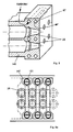
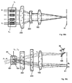
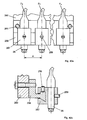
- Fig. 4 is a section through an application example of a laser cannon with sixteen fiber lasers, which are coupled via terminators 26, and with a modulation unit, consisting of two multi-channel acousto-optic modulators 34 shown.
- the laser cannon is a multi-part receptacle for adapting the optical unit and contains sockets 29 (FIG. Fig. 4a ) with mating surfaces for the fits of the terminators 26, means for merging the individual laser beams, the modulation unit, a transmission unit for transmitting the laser radiation, which is to cause a processing effect, on the processing surface and an arrangement for rendering the laser radiation harmless, which is not to produce a processing effect.
- An arrangement for removing the material removed from the processing surface may be arranged on the laser gun, but it may also be arranged in another way in the vicinity of the processing surface.
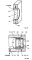
- Fig. 4a is a perspective view too Fig. 4 .
- Fig. 4b is a variant too Fig. 4 shown in which the beams of each fiber laser not as in Fig. 4 parallel, but at an angle to each other, but what from the sectional drawing in Fig. 4b is not apparent and therefore in the Fig. 21, 22nd and 24 is explained in more detail.
- Fig. 4c is a variant too Fig. 4b shown, which allows an advantageous, much more compact design due to a differently executed transmission unit.
- a housing 35 are at the radiation entrance 9 ( Fig. 1 ) each have 4 fiber lasers F HD1 to F HD4 , F VD , to F VD4 , F HR1 to F HR4 , F VR1 to F VR4 via the terminators 26 by means of the sockets 29 ( FIG . Fig. 4a ) are arranged side by side in a plane in four tracks each to a beam packet.
- the embodiment of in Fig. 4 used end pieces 26 is in Fig. 9 described in more detail.
- the terminators should preferably be inserted gas-tight in the housing 35, including seals 36 (FIGS. Fig. 4a ) can be used. It can instead of in the Fig.
- terminators also differently shaped terminators are used, as in the Fig.5, 5a . 5b, 5c . 6, 6a . 7 . 9, 9a . 10, 10a, 10b . 11, 11a, and 12 are described, if corresponding sockets 29 are provided in the housing 35.
- Fig. 3 singlemode fibers or other fibers 28 may be attached to the fiber lasers before the terminators 26 are applied.
- it can also be an arrangement of the laser fibers 5 or fibers 28 according to 40, 40a, 40b, 40c, 40d and 41st Find application.
- the fiber lasers F HD1 to F HD4 or F VR1 to F VR4 should have a different wavelength than the fiber lasers F VD1 to F VD4 or F HR1 to F HR4 .
- F HD1 to F HD4 and F VR1 to F VR4 have a wavelength of 1100 nm
- F VD1 to F VD4 and F HR1 to F HR4 should have a wavelength of 1060 nm, which can be achieved by a corresponding doping of the laser-active core material of the laser fiber 5.
- all fiber lasers can also have different wavelengths if they are combined accordingly.
- wavelength-dependent mirror 37 as a means for merging the beam packets of the fiber lasers F HD1 to F HD4 with those of the fiber lasers F VD1 to F VD4 and the beam packets of the fiber lasers F VR1 to F VR4 with those of the fiber lasers F HR1 to F HR4 to one radiation packet F D1 to F D4 and F R1 to F R4 ( Fig. 4a ) united.
- wavelength-selecting elements such as Brewster plates, diffraction gratings or narrowband filters can be introduced in the area of the laser fibers between the input mirror 7 and the output mirror 12.
- the inventive embodiment of the beam merging is not limited to the use of fiber lasers of different wavelengths.
- fiber lasers which have no preferential direction in the polarization of the emitted laser radiation
- fiber lasers which emit polarized laser radiation.
- the use of the end piece 26 is after Fig. 9 with square cross section particularly suitable because one can produce by turning the end piece by 90 ° before mounting in the housing 35, one or the other polarization direction with the same fiber laser.
- a particular advantage of merging multiple lasers into a single spot, namely to each of the individual processing points B 1 to B n (for example, B 1 to B 4 in FIG Fig. 20-22 ) is the achievement of a higher power density at a given spot size on the processing surface 81.
- F HD1 to F HD4 is populated, of which, for example, F HD1 and F HD2 after Fig. 15 from one fiber laser and F HD3 and F HD4 from another fiber laser. If that is in Fig.
- a portion of the laser radiation can be coupled via a beam splitter, which is not shown, and passed to a measuring cell, not shown in the figures, to produce therefrom a measured variable as a comparison value for a Regulating the output power of each fiber laser can be used.
- a measuring cell not shown in the figures
- the number of levels in which the terminators are arranged is not limited to the described one level.
- Fig. 29 . 32 . 33 and 41 are z.
- Fig. 38 a layout with 2 levels is shown.
- each a four-channel acousto-optic modulator 34 its mode of action and embodiment in the Fig. 17, 18 . 19 and 19a is explained in more detail, the respective beam packets of the fiber lasers are modulated.
- the acousto-optic modulator 34 which is a deflector in principle, the unwanted energy is deflected from the original beam direction I 0 in the beam direction I 1 in the illustrated case ( Fig. 4a ), so that they can be easily intercepted later in the beam path and rendered harmless.
- the modulation can preferably be done digitally, ie it is different in the individual modulator channels only between two states, namely "ON" and "OFF", which is particularly easy to control; but it can also be done analogously by the laser power in each modulator channel can be set to any value.
- the modulation is not limited to that the energy from the beam direction I 0 is used for the machining and the energy from the direction I 1 is rendered harmless.
- the deflected beam direction I 1 is used for processing and the energy from the direction I 0 is rendered harmless.
- a small portion of the modulated radiation power of the individual modulator channels can be given to a respective measuring cell via a beam splitter, not shown, to a measured variable which is used as a comparison value in a closed-loop control circuit for accurately controlling the laser energy of each track on the machining surface.
- the multi-channel acousto-optic modulator 34 is preferably mounted on a cylindrical modulator housing 41 which is rotatably mounted in an opening 48 in the housing 35. After the modulator housing has been adjusted to the required Bragg angle ⁇ B , the modulator housing is fixed by means of a connection 42. By means of a seal 43 is ensured that each modulator housing gas-tight to the housing 35 closes. From the modulator housing 41 protrudes a specially prepared circuit board 171 in the inner space 44 of the housing 35, via which the electrical connections to the piezoelectric transducers 45 are made.
- the preferred embodiment of the modulators is in the FIGS. 19 and 19a described in more detail.
- the radiation packets F D1 to F D4 and F R1 to F R4 are guided to a strip mirror 46 which is inserted in the Figs. 26, 26a, 27, 27a, and 27b is described in more detail.
- the beam packet F D1 to F D4 is arranged with respect to the strip mirror 46 so that it can pass through the strip mirror unhindered.
- the laser beams of the beam set F R1 to F R4 are offset from the beam packet F D1 to F D4 by half a track pitch and strike the strip-shaped strips of the strip mirror. As a result, they are deflected in their direction and are now in one plane with the laser beam bundles F D1 to F D4 .
- a significant advantage of the arrangement according to the invention is that the axes of symmetry of the beam packets F HD1 to F HD4 and F D1 to F D4 lie on the axis of the housing 35 defined by the bore 47 and the beam axes of the associated beam packets parallel or perpendicular to This axis is what allows a simple and precise production.
- it is possible to correct small differences in the position of the beam packets by adjusting the wavelength-dependent mirror 37 and the strip mirror 46. It is possible to readjust the terminators after installation in their position and their angle assignment, for example, for individual optimization of the Bragg angle in the individual channels, but this is not shown in the figures.
- the number of tracks reduced can be further increased, for. B. can be made by juxtaposing eight instead of four terminators, which are connected to fiber lasers to a beam packet doubling the number of lanes. This would require the use of two 8-channel acousto-optic modulators. Acousto-optic modulators with 128 separate channels are available on a crystal.
- Operation with multiple tracks of lasers and multiple lasers in one track enables high processing speeds with low relative velocity between the laser gun and the workpiece. Also, hereby, the processing speed can be optimally adapted to the time constant of the heat dissipation of the material. For a longer processing time, too much energy flows uselessly into the environment.
- the housing 35 is sealed gas-tight with a lid and a seal, both of which are not shown in the figures.
- a cylindrical tube 51 is flanged in the region of the bore 47 and sealed by a seal 52.
- the cylindrical tube contains as a transmission unit optics, namely two tubes 53 and 54, each with an optical imaging system, the eight laser beams F D1 to F D4 and F R1 to F R4 at the radiation exit 10 (FIG. Fig. 1 ) on the working surface to the correct scale.
- the beam path is in Fig. 4 shown as a side view.
- Fig. 20 the principal ray path is shown as a plan view for the radiation packet F HD1 to F HD4 .
- the wavelength dependent mirrors, the modulators and the streak mirror are not shown there.
- plano-convex lenses are mainly shown, but it is also possible in all figures other lens shapes such.
- optical imaging systems may preferably be made telecentric.
- the lenses 55 and 56 may be connected by screwing or by gluing to the tube 53, but they may preferably be metallized at their edges and soldered to the tube 53.
- the tube 54 is preferably sealed gas-tight with a seal 62 relative to the cylindrical tube 51.
- the chambers 66 and 67 are preferably via bores 71 with the spaces 44 and 63 connected.
- the tubes 53 and 54 may preferably have openings 72.
- the principle of the interception assembly 73 is in Fig. 18 described in more detail.
- the interception assembly 73 is inserted with a seal 76, and the concave lens 75, which is also by another optical element, for example a glass plate can be replaced, glued into the interceptor or preferably metallized in its edge zone and soldered for better heat dissipation to the interceptor.
- the space 63 is sealed gas-tight from the environment.
- the spaces 44, 63, 64 and 65 and the chambers 66 and 67, so the entire interior of the laser gun, can preferably be evacuated or filled with a protective gas.
- the spaces and chambers should be as free as possible of components that secrete gases or particles, because it could settle dirt on the highly loaded optical surfaces, which would lead to premature failure of the arrangement. Therefore, the requirement is made to the seals to be used that they do not secrete particles or gases.
- great value is placed on the highest purity of the parts to be assembled and the environment until the laser gun is closed. After closing the laser gun 23 can be made via the valve 77 an evacuation of the entire interior or a protective gas can be filled.
- the advantage of filling the interior with inert gas is that it can be replaced more easily by connecting a gas cylinder, not shown, to the valve 77 via a pressure reducing valve during operation, from which gas can be added to the housing as needed.
- Another advantage is that when replacing a fiber laser one end piece is to be removed from the housing and replaced by another or if the housing or the cylindrical tube has to be opened by the user for some reason, one constantly during the process small amount of the inert gas can flow through the housing, so as to prevent the ingress of dirt particles in the protected space.
- the angle between the beam packets of the original beam direction I 0 of the acousto-optic modulator and the deflected beam direction I 1 is significantly increased by the imaging system of the lenses 55 and 56, so that it is easy, by means of the high-reflection mirror 74 on the interceptor assembly 73rd to intercept the unwanted radiation packet of the deflected beam direction.
- the mirror 74 is preferably made of metal and provided with a highly reflective layer to minimize heating due to absorbed laser energy. It is connected to the tube 51 for better heat dissipation via a strong flange of the interceptor assembly 73. But you can also dispense with the interception, if instead of the highly reflective mirror, an optical component such. B.
- a lens that slightly modifies the laser radiation to be intercepted in their optical properties, that the focus of the diffracted radiation is different from the focus of the radiation used for material processing. If the radiation to be intercepted were then conducted onto the processing surface, the radiation to be absorbed would not have the required power density in order to remove material, but would be uselessly absorbed and reflected.
- the advantage of the arrangement after Fig. 4 is that low demands are placed on the optical components in the two tubes. You could even do both tubes completely the same.
- Another advantage is that the axes of the end pieces 26 are parallel to each other.
- the distance between the objective lens 61 and the processing surface 81 must not be too small so that particles flying away from the material surface do not reach the objective lens. If it is contaminated, it absorbs laser energy passing through it and is destroyed and thus unusable.
- a special mouthpiece 82 is arranged between the objective lens 61 and the processing surface 81, the under Fig. 34 is described in more detail.
- the laser gun 23 of the laser radiation source is within the arrangement for material processing ( Fig. 3 ), for example on a prism 83 around the optical Axis which is identical to the axis of the cylindrical tube 51, 95, rotatably mounted and displaceable in the direction of the optical axis and fixed with a clamping band 85 or with a plurality of clamping bands in their position.
- a prism 83 around the optical Axis which is identical to the axis of the cylindrical tube 51, 95, rotatably mounted and displaceable in the direction of the optical axis and fixed with a clamping band 85 or with a plurality of clamping bands in their position.
- a plate 86 having openings 87 through which a coolant can be pumped.
- the task of this plate 86 is to absorb the laser energy intercepted from the beam path of the transmission unit and to divert what is in Fig. 18 is shown in more detail.
- the plate 86 and the tube 51, 95, 113 is a thermal insulation, which is not shown in the figures.
- the plate is connected to the tube 51, 95, 113 via insulating flanges 91.
- the flanges 91 also prevent the leakage of laser radiation.
- the track pitch of the laser tracks on the processing surface 81 can be changed, which in Fig. 35 is shown in more detail. It is within the scope of the invention that the rotation of the laser gun to adjust the track pitch and the adjustment of their distance to the working surface not only manually, but by means of a suitable, preferably electronic control and / or regulation can be performed.
- suitable measuring devices not shown, may also be provided, which are located in the vicinity of the processing surface and can be approached by the laser gun as needed.
- Another way to adjust the track spacing is in the Fig. 36, 36a . 36b, 36c and 37 described.
- Vario-focusing optics can be used to adjust the track pitch and the best focus.
- Such Vario-focusing optics preferably has two fixed lens systems in addition to fixed lenses, wherein an adjustment of the first lens system mainly causes an adjustment of the magnification, whereby the track pitch can be influenced and wherein an adjustment of the second lens system mainly causes an adjustment of the focus.
- An iterative setting can be made to optimize track pitch and best focus.
- it is possible it is possible between the lenses 57 and 61 to arrange a not shown, movable, long focal length lens, with the focusing of the processing points on the processing surface can be fine adjusted without moving the radiation source, because the resulting focal length of two lenses depends on their distance.
- the optical elements in the beam path will heat up because they absorb a, albeit very small, part of the laser energy.
- the critical optical components instead of glass made of a material with better thermal conductivity, for example made of sapphire.
- the loss of heat is dissipated by metallization of the bonding surfaces of the optical components through the solder joints to the sockets and to the housing.
- the housing is designed for better heat dissipation with cooling fins 92, which can be cooled by a fan, not shown.
- an enforcement of the housing 35 and the other components of the laser radiation source with holes, especially in the critical areas on the lens frames and sockets for the end pieces 26, possible, through which a coolant can be pumped, which in the Fig. 8 and 39 is shown.
- the objective lens (61, 103 and 112) is provided with a replacement socket so that it can be swapped quickly by the user of the laser radiation source, whether it has been contaminated during operation or that another magnification is desired. In this case, it is advantageous that the bore 72 is not performed at the tube 54.
- Fig. 3 It is shown that the laser radiation does not impinge perpendicularly but at an angle on the material to be processed, so that the radiation reflected on the material surface can not return to the laser radiation source.
- Fig. 4 . 4b . 4c and Fig. 18 shown that the laser radiation to be destroyed by an inclined concave lens 75 in a sump, consisting of an inclined plate 86, which can be cooled, is passed.
- another optical component for example a plate or a diaphragm, may also be used.
- this optical component is dimensioned in its effective diameter so that the guided into the sump laser radiation can happen just while such radiation, which is reflected back from the sump or scattered back, is largely retained, so that no energy back into the laser can get.
- the surface of the plate 86 which is shown in the figures as a flat surface, can also be made spherical or hollow and preferably roughened in order to absorb a maximum amount of radiation and to reflect or scatter a minimum of radiation.
- Fig. 38 for two levels shown that by low parallel displacement of the beam axes of the exiting beam from the end piece oblique impact can be achieved on all affected lens surfaces.
- the acousto-optical modulator 34 is already rotated by the angle ⁇ B with respect to the axis of the beam, but it can also be rotated by the angle ⁇ relative to the axis of symmetry of the beam, or it can be an arrangement according to Fig. 24 be used, in which the axes of the beams emerging from the terminators at an angle to each other. It has been shown in practice that already angle differences of 1 to 2 degrees between the solder on the optical surface and the axis of the beam are sufficient to gain security against radiation reflected back into the lasers.
- a further laser gun according to the invention for a laser radiation source is shown, which differs from the in Fig. 4 illustrated laser gun by a housing 93, a closing piece 94, a cylindrical tube 95, a tube 96 and a highly reflective mirror 97 differs.
- the housing 93 has the terminations 94 matching sockets 29.
- the terminators 94 preferably correspond to those of Fig. 10, 10a and 10b , the axes of beams do not run parallel in the respective ray packets. but about to the center of the concave lens 101 too, which in plan view Fig. 21 is shown. But it can also all other terminators according to the Fig. 5, 5a . 5b, 5c ; 6, 6a ; 7 . 9, 9a; 11, 11a and 12th used, if it is ensured that the sockets 29 are arranged at a corresponding angle.
- the transmission unit which consists of 3 lenses, namely a diverging lens, so a concave lens 101 and two converging lenses, ie convex lenses 102 and 103, wherein the convex lens 103 is preferably designed as a replaceable objective lens.
- the tube 96 may be evacuated in the space between the lenses 101 and 102, or filled with an inert gas, or preferably connected via a bore 104 to the space 105, which in turn is connected to the space 107 via a bore 106.
- the space 107 is connected to the space 111 via the bore 47, which in turn is sealed gas-tight, as under Fig. 4 and Fig. 4a described.
- the space between the lenses 102 and 103 may be connected via a bore, not shown, with the space 105, in particular when the socket of the lens is sealed gas-tight or as below Fig. 4 described constantly a small amount of the protective gas flows through the laser gun and exits near the objective lens, but not in Fig. 4b is shown.
- the entire interior of the laser gun consisting of the spaces 111, 105, 107, is preferably evacuated or filled with an inert gas or by a protective gas flows through, as under Fig. 4 and Fig. 4a has been described in detail.
- the unwanted beams are intercepted with a highly reflective mirror 97, but in contrast to Fig. 4 no lens system is present, which acts winkelver Anlagenrnd so that the distance between the highly reflective mirror and the modulators is kept correspondingly large here in order to achieve a sufficient spatial separation of the beam packets I 0 and I 1 .
- the entire length of the laser gun is similar here to the arrangement of Fig. 4 ,
- the optical beam path of the transmission unit in Fig. 4b represents a side view.
- Fig. 4b represents a side view.
- FIG. 21 is a principal ray path for a top view Fig. 4b specified.
- the optical path of the lenses 101 and 102 corresponds to that of a Galiläi inverted telescope, but it can also be implemented as an inverted Kepler telescope by replacing the short-focal-length concave lens 101 with a convex lens.
- Such telescopes are in the textbook “ Optics "by Klein and Furtak, Springer 1988, pp. 140-141 described.
- the advantage of the arrangement after Fig. 4b is that only 3 lenses are required for the transmission unit.
- the disadvantage that the beams of the individual terminators are not parallel, is provided by terminators according to the Fig. 10, 10a and 10b Fixed.
- One could also use a lens 55 to redirect the beams in the desired direction, as in FIG Fig. 20 was presented. Then, the individual laser beams between the end pieces 26 and the lens 55, as shown in FIG Fig. 4 is arranged, run parallel to each other, and there is no difference with respect to the housing and the end pieces or their arrangement Fig. 4 , However, since the lens 55 in addition to the deflecting effect also exerts a collecting effect on the individual beam, would not arise at the location of the concave lens 101, the same conditions as in Fig.
- the lenses 102 and 103 are also possible into a single, common lens. Then there is a transmission unit with only 2 lenses. Furthermore, it is possible, preferably between the lenses 101 and 102, to arrange a displaceable, long-focal-length lens, not shown, with which the focusing of the processing points on the processing surface can be finely adjusted without displacing the radiation source. It is also possible to use a vario-focusing optics as described in Fig. 4 was mentioned.
- a special mouthpiece 82 is provided to prevent contamination of the objective lens 112 and under Fig. 34 will be described in more detail.
- Fig. 4c shows a laser gun, which is designed to be much more compact than that of Fig. 4 and Fig. 4a .
- an objective lens 112 used in conjunction with a mirror assembly can be exchanged to obtain various imaging scales.
- a Vario-focusing optics can be used. According to the invention but can also be an image with the mirror assembly alone, without additional objective lens 112 done.
- the beam path is folded by means of the two mirrors 121 and 115.
- the domed mirror 121 is preferably made of metal. He is closely connected to the highly reflective mirror 97 and preferably made with him together from one piece.
- the convex surface of the domed mirror may be spherically or aspherically shaped.
- the mirror 115 is concave, so a concave mirror. Its surface may be spherically shaped but is preferably aspherical in shape. It is preferably made of metal. Metal has the advantage of good dissipation of heat loss.
- the high-reflection mirror 97 and the curved mirror 121 can be made in one piece and preferably in one operation with the same shape of the surface produced and mirrored together, which is particularly easy to manufacture and very advantageous for the positional stability of the curved mirror.
- the modulation of the laser energy by means of the acousto-optic modulator it strikes either the curved mirror 121 or the highly reflective mirror 97.
- the curved mirror 121 has taken over the function of the high-reflection mirror 97 in an advantageous manner.
- the highly reflective mirror 97 may also have a different shape of the surface than the curved mirror 121 and, for example, be a plane mirror.
- the beam path is similar to that of a reverse mirror telescope according to Herschel, which instead of the curved mirror contains a convex lens, and is in Fig. 22 described in more detail.
- Mirror telescopes are in the " Textbook of Experimental Physics Volume III, Optics "by Bergmann-Schäfer, 7th edition, De Gruyter 1978 , described on page 152.
- the interceptor assembly 73 is gas-tight over a seal 76 over which the unwanted laser energy, as under the Fig. 4 . 4b and 18 described, to a cooling plate 86 with holes 87 derived and rendered harmless. It is also possible, already at the location of the plate 114 to intercept the unwanted laser radiation from the radiation packet I 1 and render it harmless.
- the space 111 in the housing 93 is connected to the cavity 123 via the bore 122. Both rooms can be evacuated or preferably with one Protective gas filled or flowed through by a protective gas, as already described.
- the socket 116 is mounted, which receives the interchangeable objective lens 112.
- a gasket 124 closes off the cavity 123 in a gastight manner.
- the socket can receive a tempered plate 117, the edge of which is preferably metallized, and which is preferably gas-tight soldered to the socket.
- the space between the objective lens 112 and the highly annealed plate 117 may also be connected to the space 123 via a bore, not shown, especially when the entire laser gun as shown in Fig. 4 described, is constantly flowed through by a protective gas which exits in the vicinity of the objective lens 112, which in Fig. 39a is shown.
- the highly annealed plate 117 may also include optical correction functions known from the Schmidt optics known in the literature to improve the optical imaging quality of the device.
- the eccentric tube may be provided with cooling fins 92, which can be blown by a fan, not shown, to better dissipate the heat loss to the environment.
- the laser gun is rotatably mounted in a prism about the axis between the concave mirror and the objective lens to the track spacing as shown Fig. 4 described adjustable and set the correct distance to the processing surface 81.
- the laser cannon can be fixed with a strap 85.
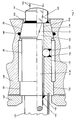
- FIG. 12 is a preferred embodiment of a terminator 26 for a fiber 28 or laser fiber 5, which is also a fiber.
- sensors and measuring technology connectors for optical fibers for low power are known, but are not suitable for high performance, because too high heating occurs, which leads to destruction.
- beam shaping and coupling optics are described.
- the performance of these systems is limited to 1000 mW and is thus a factor of 100 below the requirements for the intended applications in material processing, because sufficient heat dissipation is not guaranteed.
- the terminator consists of an elongated housing 132 having a continuous, axially extending, cylindrical opening 130.
- the housing is preferably made of prefabricated, for example, drawn material, which may preferably be made of glass.
- the laser fiber 5 of the fiber laser is preferably freed on its last end of its coat and preferably roughened on its outer surface, as in the German patent application P 197 23 267 is described, so that the remaining pump radiation leaves the laser fiber before entering the laser fiber in the end piece.
- the fiber 5, 28 may additionally be surrounded by a single-layer or multi-layer protective sheath 131, which may be connected to the housing 132 of the terminating piece, for example by means of an adhesive 142.
- the housing 132 has fits 134, with which the housing in a socket 29 (FIG. Fig. 5a . Fig. 7 . Fig. 8 . Fig. 14 ) can be used exactly. The fits can extend over the entire length of the housing ( Fig. 5b . 9 .
- One or more seals 36 can be provided, which are connected to the housing 132, for example by means of adhesions 142. The task of the seals is to allow a gas-tight connection of the terminators with the sockets 29.
- the housing may have a different, for example, smaller diameter in the region of the protective jacket 131 and the seal 36 than in the region of the fits. At one end of the housing 132, the end of the fiber 28 and the laser fiber 5 is received and guided within the housing in the opening 130.
- a short-focal-length lens 133 is attached, wherein the housing may have a conical extension 139 in order not to hinder the laser radiation 13.
- the radial position of the fibers 5, 28 can also be determined by the cylindrical opening 130, wherein the fiber is axially displaceable within the opening.
- the position of the lens 133 can either be mounted with sufficient precision during assembly or axially and / or radially adjusted and fixed by suitable means, not shown, with respect to the fibers 5, 28 and to the fits 134, whereby the fiber can also be displaced axially ( Fig. 5b ).
- the adjustments are advantageously made with a measuring and adjusting device. Through the adjustment is to be achieved that the emerging from the lens 133 beam 144 is brought to the fits 134 in a predetermined axis and focus position with a defined cone. After a fixation of the fiber 5, 28 within the housing 132 and the lens 133 on the housing, the measuring and adjusting device is removed.
- the end of the fiber 5, 28 in the region of the end piece before assembly with a suitable coating, for example, a correspondingly thick metallization 141, in order to improve the durability of the adjustment.
- the fixation of the fiber 5, 28 within the housing 132 can be done by suitable means such as gluing, soldering or welding.
- an elastic mass 138 is preferably provided which provides additional protection for the fiber.
- the lens 133 preferably on its side facing the fiber end by appropriate shaping and vapor deposition of a corresponding layer and align it so that it takes over the function of Auskoppelspiegels 12 for the fiber laser.
- Fig. 5a shows a multiple arrangement of fiber laser outputs by means of the terminators Fig. 5
- bores 150 are provided for receiving two terminators 26 for two tracks.
- three pins 148 and 149 are mounted in rows so that they have a lateral boundary as a socket 29th represent for the terminators and ensure precise guidance and alignment of the terminators.
- the diameters of the pins 148 are denoted by d 1 and preferably equal to one another.
- the diameters of the pins 149 are denoted by d 2 and also preferably equal to each other.
- the axes of the beams of both tracks would be parallel to one another in the plane of the drawing, since the terminators 26 have cylindrical fits 134. But they are in Fig. 5a the diameters of the pins 149 are greater than the diameters of the pins 148, which results in the axes of the two beams in the plane of the drawing being at an angle to each other. The angle between the beams is dependent on the diameter difference d 2 - d 1 and the center distance M of the two rows of pins.
- the terminators are guided on the bottom in a plane through the housing 145 and are guided from above by a cover, not shown, of the housing which is fixed to the housing and can seal it gas-tight by means of a seal, not shown.
- the housing 145 may be part of a receptacle for an optical unit for shaping the laser radiation.
- the terminators are secured by means of tabs 147 and screws, not shown, on the housing 145, wherein the seals 36 provide a gas-tight seal.
- the assembly is not limited to two lanes, additional bores 150 may be provided, and additional pins 148 and 149 may be employed to insert further terminators for additional lanes.
- pins 148 and 149 are also used to create a defined distance between the planes.
- the pins extend horizontally between the end pieces.
- the horizontally disposed pins 149 extend between the wall of the housing 145 in which the bores 150 lie and the row of the vertically arranged pins 149 shown.
- the horizontally arranged pins 148 preferably run in a distance M parallel to the horizontally arranged pins 149.
- the pins 148, 149 are preferably made of drawn steel wire, but they can also be made of other materials, such as drawn glass.
- An advantage of the multiple track and / or multi-level arrangement as shown is that the bars 148, 149 have some flexibility. This makes it possible to compress the entire package of the end pieces in the direction of the tracks and in the direction of the planes so that the end pieces 26 abut with their fits 134 without clearance on the pins, which is desirable for achieving the highest precision.
- a termination piece 26 is shown in which means for adjusting the position of the fiber 5, 28 are provided within the end piece to adjust the position of the fiber 5, 28 to the lens 133 within the end piece and with respect to the fits 134. It can also be adjusted the position of the lens.
- the adjustments are advantageously made with an adjusting device.
- adjusting screws 135, 136 (FIG. Fig, 5b, 5c . 9, 9a . 10a, 10b . 11, 11a, 12 ) and / or or balls 137 ( Fig. 6, 6a . 7 ) be provided.
- the fiber 28 or laser fiber 5 can also be displaced axially.
- the position of the lens 133 can either be sufficiently precisely mounted during assembly or axially and / or radially adjusted and fixed by means not shown with respect to the fibers 5, 28 and to the fits 134, whereby the fiber can also be displaced axially.
- the adjustments are advantageously made with a measuring and adjusting device.
- the measuring and adjusting device is removed.
- the under Fig. 5 Said, for example, for the metallization 141, the elastic mass 138 and the use of the lens 133 as a laser mirror.
- Fig. 5c is a cross section through the end piece 26 shown in the adjustment screws, it can be seen that distributed around the circumference, preferably 3 adjustment screws 135 are provided with which the fiber 28 and the laser fiber 5 is finely adjustable in the housing. Furthermore, at the end of the end piece 26, on which the fiber 28 or the laser fiber 5 enters, further adjusting screws 136 may be provided inside the end piece, as they are described in US Pat Fig. 5b are shown. These adjusting screws are formed like the adjusting screws 135. If only one set of adjustment screws 135 is used, one can adjust the fiber 28 or the laser fiber 5 only with respect to the angle. If two sets of adjustment screws are used, you can also move them parallel to their axis. The fixation of the fiber 5, 28 within the housing 132 can be done by suitable means such as gluing, soldering or welding.
- Fig. 6 shows an embodiment of the end piece 26, in which instead of adjusting screws small balls 137 made of metal or preferably metallized glass are used, which are placed in the housing in their position and then glued or soldered. It is also possible to attach several sets of balls.
- Fig. 6a shows a cross section through the end piece in the region of the balls 137th
- the connections in the Fig. 5 . 5b . 5c . 6 . 6a . 7 . 9 . 10 . 11, 11a and 12th between the lens 133 and the housing 132 and between the adjusting screws 135 and 136 and the balls 137 and the housing 132 are hermetically sealed. This can be done by suitable adhesive or solder joints 142. In the case that a solder joint is preferred, the glass parts are metallized at the corresponding locations 141 beforehand.
- the adhesive or solder joints can also fill the remaining gap between the fiber 28 or the Laserfber 5 and the housing 132 and the protective sheath 131 in the vicinity of the end piece wholly or partially, which, for example, in Fig. 5 is shown. Furthermore, it is possible to permanently evacuate the interior 143 of the housing or to fill it with a protective gas.
- Fig. 7 shows a further embodiment of a termination piece 26 which is inserted in a housing 145 with a socket 29.
- the front outer fit 134 is tapered in the region of the lens 133 for better sealing and better heat dissipation.
- a seal 146 may be provided, which may be mounted on the lens-side end of the end piece, as shown, also at its fiber-side end.
- Fig. 8 are sockets 29 in a housing 145 for a plurality of tapered terminators 26 according to Fig. 7 shown.
- Such versions are advantageous if several outputs of fibers or fiber lasers are to be arranged side by side or side by side and one above the other.
- the axes of the sockets can be arranged so that the axes of the exiting from the terminating beams of adjacent and / or superimposed terminators to each other parallel or at an angle.
- the housing 145 may be provided according to the invention with holes through which a coolant is passed.
- Fig. 8a shows the rear attachment of the end pieces 26 in the housing 145.
- tabs 147 are provided, which are the ends of the end pieces at the points at which the fibers in each case in the Enclosure of the end pieces 26, 94 enter, fix by means of screws 151 in the housing.
- Fig. 9 shows an embodiment of a termination piece 26 with a square or rectangular cross-section, in which all opposite outer surfaces are parallel and fits 134 may be.
- Fig. 9a shows a cross section through the tail 26 after Fig. 9 with square cross section.
- Fig. 10 shows an embodiment of the end piece 94 with a rectangular cross-section, wherein two opposite outer surfaces trapezoidal and two opposite outer surfaces parallel to each other. It can also extend all opposite outer surfaces trapezoidal to each other.
- the outer surfaces may be fits 134.
- Fig. 10a is a longitudinal section and in Fig. 10b is a cross section through the end piece according to Fig. 10 shown.
- Fig. 11 end pieces 26 are shown with trapezoidal cross-sections, so that when a series of succession of end pieces by successive rotation of the end pieces by 180 °, a series of terminators, in which the centers of the terminators lie on a central line. If desired, a plurality of such rows can be stacked on top of each other, which can be seen in FIG Figure 11 indicated by dashed lines.
- End pieces 26 are shown with triangular cross-section, which can also be arranged in several rows one above the other, which is indicated by dashed lines.
- Fig. 12 shows end pieces 26 with hexagonal cross-section, which can be arranged honeycomb to increase the packing density.
- terminators according to the invention advantageously allow a structure of the laser radiation source of individual modules.
- Fig. 13 shows an application example of the end piece 26 and 94 in a fiber 28 and a laser fiber 5, which are provided at both ends with a respective end piece according to the invention.
- the lens 133 preferably on its side facing the fiber end by appropriate shaping and vapor deposition of a corresponding layer so that it takes over the function of Auskoppelspiegels 12 with. It is also possible according to the invention, the lens 3, 154 by appropriate shaping and vapor deposition of a corresponding layer to be carried out so that it takes over the function of the coupling mirror 7 with.
- Fig. 14 shows a coupling of the laser fiber 5 to a pump source by means of the end piece 26 via the housing 152, in which the pump source 18 is housed in a recess 153 preferably gas-tight.
- a seal 146 ensures that the end piece 26 also closes gas-tight, so that no dirt particles can penetrate into the recess from outside and they can be evacuated if necessary or filled with a protective gas.
- a continuous flow of shielding gas can also flow through the recess 153, in particular if the termination piece 26 is temporarily removed.
- the radiation of the pumping source 18 is directed to the pumping cross section the laser fiber 5 focuses.
- the pump source may consist of one or more laser diodes, but it may also consist of an array of one or more Lasem, in particular fiber lasers whose output radiation has been combined with suitable means so that a suitable Pumpfleck arises.
- Fig. 15 shows the branching of the output radiation from the laser fiber 5 of a fiber laser by means of a fiber fusion coupler 155.
- Such fiber fusion couplers are in the Fig. 20 described closer catalog of Spindler and Hoyer on page G16 for single-mode fibers and can be melted according to precise alignment directly to the output of the laser fiber 5.
- the termination piece 26, 94 is in this case connected to a passive single-mode fiber or to another fiber 28 and not directly to a fiber laser with the active laser fiber 5.
- Fig. 16 shows the combining of the radiation from the laser fibers 5 of two fiber lasers via a fiber fusion coupler 156.
- the cross sections of the two input fibers are combined into one fiber.
- the diameter of the fibers at the two inputs of the Faserschmelzkopplers 6 microns and the core diameter of the two laser fibers to be fused is also 6 microns.
- the diameter at the output of the fiber fusion coupler can also be greater than 9 .mu.m and more than two outputs of fiber lasers or fibers can be combined.
- the termination piece 26, 94 is in this case connected to a passive single-mode fiber or other passive fiber 28 and not to a fiber laser with the active laser fiber 5.
- optical waveguides can also be welded to the fiber lasers or coupled in another way, for example via optics.
- One or more passive single mode fibers or one or more other passive fibers 28 may be attached to a single fiber laser instead of a splitter Fig. 15 or a unifier Fig. 16 connect via optics to connect to this singlemode fiber or other fiber then to the terminator.
- Fig. 17 shows the principle of an acousto-optic deflector.
- a piezoelectric transducer 45 is applied, which is supplied from a high frequency source 162 with electrical energy.
- a laser beam 163 incident at the Bragg angle ⁇ B is deflected out of direction by interaction with the ultrasonic field 164 within the crystal in proportion to the frequency of the radio frequency source.
- the rays are focused on the processing surface 81.
- the frequency f 1 gives a direction I 11 (first first-order beam) and the frequency f 2 a direction I 12 (second first-order beam). Both frequencies can also be present at the same time and at the same time the beams I 11 and I 12 , which can be modulated by changing the amplitudes of the high-frequency sources.
- An optimal transmission efficiency for the coupled radiation arises in each case when the Bragg angle is half the angle between the direction of the beam I 0 and the direction of the deflected beam. For use as acousto-optic modulator only one of the partial beams is used. It is most effective for material processing to use the zero order beam because it has the greater power.
- first-order beams it is also possible to use one or more first-order beams.
- the energy of the unused beams is rendered harmless by, for example, being converted into heat on a cooling surface.
- Fig. 17 If only one piezoelectric transducer 45 is provided, therefore only one laser beam 163 can be deflected or modulated.
- the individual channels are designated T 1 to T n . If you like, in Fig.
- the acousto-optic modulator puts in the one focal point of the lens 165 and performs the beam path through the acousto-optic modulator almost parallel, the rays are focused in the other focal point of the lens 165 on the processing surface arranged here and the beam axes between the lens 165 and the processing surface 81st run parallel and meet perpendicular to the working surface.
- Such an arrangement is called telecentric; the advantage is that the distance between the beam axes remains constant as the position of the processing surface changes. This is of great importance for precise material processing.
- Fig. 18 is shown how the unused beam is rendered harmless.
- the unused beam is intercepted and deflected by a highly reflecting mirror 166, which is preferably made of metal for better heat dissipation, scattered by a concave lens 75 and directed onto an obliquely arranged plate 86 with bores 87 that does not introduce energy into the laser can be reflected back.
- the plate 86 and optionally also the mirror 166 are cooled by a cooling system operated by a pump 167. It is also possible to use a convex lens or a glass plate instead of the concave lens.
- the plate 86 is shown with a flat surface at an angle. You can also use a plate with a vault or a hollow. The surface may be roughened to absorb the laser energy well and transfer it to the coolant.
- a modulator of the company Crystal Technologies Inc., Palo Alto, USA which is sold under the name MC 80 and contains 5 separate deflection or modulator channels.
- the distance between the channels is specified as 2.5 mm, the beam diameter being specified as 0.6 mm to 0.8 mm.
- a similar product from the same company is equipped with 10 channels spaced 2.5 mm apart. The distance of the channels of 2.5 mm requires that the diameter or the edge length of the end pieces 26, 94 are made smaller than 2.5 mm.
- end piece 26, 94 in its diameter or in its edge length but greater than the distance of the channels in the acousto-optical deflector or modulator can by an intermediate image, as shown in Fig. 25 an adjustment is made.
- Such a multi-channel deflector or modulator can also be used in the exemplary embodiments according to FIGS Fig. 4 . 4a . 4b . 4c . 36, 36a and 37 be used. Depending on the application, not all channels need to be used. In the application examples shown only 4 channels are shown.
- Electro-optical modulators are described under the terms “laser modulators”, “phase modulators” and “Pockels cells” on pages F16 to F33 of the General Catalog G3, Order No. 650020 from Laser Spindler & Hoyer, Göttingen. Multichannel electro-optical modulators have also been used, as described in the publication "The Laser in the Printing Industry” by Werner Hülsbuch, Verlag W. Hülsbusch, Constance, on page 523 in Figure 8 -90a is shown.
- Fig. 18a an arrangement with an electro-optic modulator 168 is shown.
- an electro-optical modulator for example, the polarization direction of the not desired for processing laser radiation from the impinging beam 163, rotated (P b ) and then separated in a polarization-dependent beam splitter, which is also referred to as polarization-dependent mirror 169, the not desired for processing laser radiation P b and in a sump, for example in a heat exchanger, which may consist of a cooled plate 86, passed.
- the radiation P e desired for processing is not rotated in the direction of polarization and fed via the lens 165 to the processing surface.
- FIGS. 4 In the embodiments of the FIGS. 4 .
- the single- or multi-channel acousto-optic modulators 34 can be replaced by corresponding single-channel or multi-channel electro-optical modulators.
- the high-reflection mirror 74, 97 are replaced by the polarization-dependent mirror 169 ( Fig. 18a ), resulting in an interceptor assembly 78, and wherein the polarization-dependent mirror extends into the beam path desired for processing.
- Fig. 19 shows a plan view of an acousto-optic deflector or modulator.
- the space 44 , .111 according to the Fig. 4 . 4b and 4c in which the modulators are arranged, should be as free as possible of such components that secrete particles or gases, because it could deposit particles on the highly loaded optical surfaces, which would lead to premature failure of the arrangement.
- the electrical components of the arrangement are in FIGS. 19 and 19a arranged on a separate circuit board 171, which protrudes only with two arms in the sealed space and the electrical connections to the piezoelectric encoders 45 produces.
- the printed circuit board 171 is sealed to the modulator housing 172, preferably by means of a solder joint 173.
- the front side of the printed circuit board is preferably sealed in the region of the space 44 or 111 by a soldered metal strip, not shown.
- the printed circuit board is multi-layered to shield the individual high-frequency channels by interposed ground connections. Instead of a circuit board and a different line arrangement can be used. For example, each radio frequency channel can be connected by its own shielded line.
- the modulator housing 172 includes an access opening 174 to the electrical components.
- the modulator crystal 34 may be metallized at its base and is preferably secured by means of a solder joint or a bond 175 on the modulator housing.
- connection 176 to a cooling system to carry off the heat loss via the openings 87 by a coolant.
- the modulator housing 172 is preferably through closed a lid 177 which carries the electrical connections 181 and also contains the connections for the cooling system, but this is not shown.
- a seal 43 is ensured that the modulator housing 172 gas-tight in the housing 35 and 93 of the Fig. 4 . 4a . 4b , and 4c used and fastened by means of the connection 42.
- Fig. 20 is the principal ray path to the embodiment Fig. 4 for the beam 144 of the associated fiber lasers F HD1 to F HD4 indicated.
- the beams of the fiber lasers F VD1 to F VD4 are partially congruent with the drawn beams, but according to the invention have a different wavelength and are, as shown Fig. 4a to see about one in Fig. 20 not shown wavelength-dependent mirror 37 with the beam packet F HD1 to F HD4 to the beam packet F D1 to F D4 united.
- Fig. 20 not the beam packets of the fiber lasers F VR1 to F VR4 and F HR1 to F HR4 are shown, which, as shown Fig.
- the beams of the beam set F R1 to F R4 in Fig. 20 offset by half a track distance to the drawn rays run.
- the complete beam path instead of the drawn 4 beams contains a total of 8 beams, resulting in a total of 8 separate tracks on the processing surface.
- Fig. 20 only the two beams 144 of the fiber lasers F HD1 and F HD4 are shown.
- Fig. 4 already mentioned but more tracks can be arranged, for example, the number of tracks on the processing area can be increased to 16 separately modulated tracks.
- This arrangement allows a digital modulation of the respective laser, ie the laser is operated by turning on and off in only two states, a particularly simple control and a good shaping of the processing spot on the processing surface. This digital modulation requires only a particularly simple modulation system.
- the number of digitally possible quantization levels is already 512. It is also possible to generate the cells in two processing cycles to increase the number of tone levels.
- the modulators 34 and the strip mirror 46 are in the Fig. 20 not shown.
- the cross-section of the beam 144 from the terminator of the fiber laser F HD1 which is congruent with the beam F D1 after passing through the wavelength-dependent mirror, is hatched.
- the representation is, like all others, not to scale.
- the two drawn beam 144 result in the processing surface 81, the processing points B 1 and B 4 , which contribute to the structure of the processing spot 24 and generate on the processing surface 81 corresponding processing tracks.
- the axes of the terminators 26 and the beam 144 of the individual fiber lasers run in Fig. 20 parallel to each other.
- the beam cones of the terminators, ie the shape of the beams 144 are shown slightly divergent.
- a beam waist within the lens 133 is assumed.
- the divergence angle is inversely proportional to the diameter of the beam in the associated beam waist.
- the position of the beam waist and its diameter can be affected by varying the lens 133 in the termination piece 26, 94, and / or its distance from the fiber 28 or the laser fiber 5.
- the calculation of the beam path takes place in the known manner. See technical explanations on pages K16 and K17 of the complete catalog G3, order no. 650020 of the company Laser Spindler & Hoyer, Göttingen.
- the aim is that each of the processing points B 1 to B n on the processing surface 81 to Strahltaillen to obtain the highest power density in the processing points.
- the preferably telecentric imaging has the advantage that the diameters of the following lenses 57 and 61 need only be slightly larger than the diameter of a beam.
- the lenses 57 and 61 reduce in a second stage the image from the intermediate image plane 183 on the processing surface 81 in the manner described.
- a preferable telecentric imaging namely that the axes of the individual beams between the objective lens 61 and the processing surface 81 are parallel, has the advantage here that changes in the distance between the working surface and the laser gun do not change the track pitch, which is very important for precise machining .
- the picture does not necessarily have to be as described in 2 stages with 2 lenses each, there are other arrangements that can also generate parallel beam axes between the objective lens and the processing surface, as in FIG FIGS. 21 and 22 will be shown. Also, variations in the parallelism of the beam axes between the objective lens 61 and the processing surface 81 are tolerable as long as the result of material processing is satisfactory.
- Fig. 21 is a principal ray path to the embodiment Fig. 4b specified.
- the representation is not to scale.
- the two beams 144 of the lasers F HD1 and F HD4 are only a subset of the beams of all the lasers present in order to explain the principle.
- the axes of the individual beams of the terminators not parallel, but at an angle to each other, which is in Fig. 24 is shown in more detail and advantageous by closing pieces 94 according to the Fig. 10, 10a and 10b is reached.
- the individual beams 144 would be similar as in FIG Fig. 20 cross over without a lens 55 is required.
- the short-focal-length diverging lens that is to say a concave lens 101
- the convex lens 102 is preferably disposed at the intersection of the axis beams and together with the lens 101 forms an inverted Galilean telescope.
- parallel input beams are converted into parallel output beams of increased diameter between the lenses 102 and 103.
- the desired parallelism of each input beam can, as already described, be achieved by suitably selecting the focal length and distance of the lens 133 to the fiber 28 or laser fiber 5 in the terminators 26, 94.
- the objective lens 103 focuses the magnified beams on the processing surface 81 to the processing points B 1 to B 4 , which contribute to the construction of the processing spot 24 and generate corresponding processing marks on the processing surface 81.
- the focal length of the lens 103 By changing the focal length of the lens 103, the magnification can be easily changed. Therefore, it is advantageous if the lens 103 as an exchangeable objective lens is performed.
- the position of the lens 103 is selected so that the distance between the lenses 102 and 103 corresponds to the focal length of the lens 103, the axes of the beams between the lens 103 and the processing surface are parallel and give constant distances of the tracks on the processing surface, too at changed distance between the laser gun and the processing surface.
- Fig. 22 is the principal ray path to the embodiment Fig. 4c specified.
- the representation is, as in all other figures, not to scale.
- the beam path is the the Fig. 21 very similar, with the difference that instead of the lens 101, a curved mirror 121 and instead of the lens 102, a concave mirror 115 are used. Due to the resulting folding the beam path is considerably shorter.
- the beam path corresponds approximately to that of an inverted mirror telescope.
- Mirror telescopes are independent of the wavelength, which is advantageous when using lasers with different wavelengths.
- the aberrations can be reduced by the use of aspheric surfaces or with an optical correction plate 117, but not in Fig. 22 is shown to be corrected.
- the focal length of the objective lens 112 is equal to its distance from the concave mirror. Then, the axes of the beams between the lens 112 and the machining surface 81 become parallel, giving constant distances of the tracks on the machining surface, even with the distance between the laser gun and the machining surface changed. In addition, there is an advantageously large distance from the objective lens to the processing surface. It can also be used as described a Vario-focusing optics.
- a multi-laser array is shown in which the individual laser outputs in the form of terminators 26 are arranged on a circle segment and aim at a common crossover point 185.
- This arrangement is particularly suitable for directly modulated laser, since then results in a very low cost.
- the picture can be up the processing surface 81 with only a single lens 186 done. But it can also be an arrangement according to the FIGS. 4b or 4c to be used for illustration.
- the beam cones of the beams from the end pieces are set so that there is a beam waist and thus a sharp image for all lasers on the processing surface 81.
- the distances between the crossover point 185 and the lens 186 and between the lens 186 and the processing surface 81 are equal and correspond to the focal length of the lens 186.
- the axes of the individual beams between the lens 186 and the processing surface 81 are parallel and result in constant distances between the machining tracks, even if the distance between the laser gun and the machining surface is changed.
- multiple levels of lasers may be stacked to increase the power density and power of the laser radiation source.
- the planes of the lasers are arranged parallel to one another. Then arises as in the FIGS. 29 and 31 illustrated that the individual beams from the individual planes meet in the processing points on the processing surface 81 on a spot and thus produce a particularly high power density.
- Fig. 24 is a variant of Fig. 23 specified.
- the terminators 94 are particularly suitable for juxtaposing due to their shape. Since no directly modulatable fiber lasers are used here, a four-channel acousto-optic modulator 34 is included.
- the piezoelectric encoders 45 can, as in Fig. 24 also be arranged on a circular segment. But you can also, as in Fig.
- a diminishing intermediate image is indicated by means of the lenses 191 and 192, so that the distance between the individual end pieces 26, 94 may be greater than the distance between the individual modulator channels T1 to T4 on the multi-channel acousto-optic modulator 34.
- the imaging ratio corresponds to the ratio of the focal lengths of the two lenses 191 and 192.
- the intermediate image is preferably formed telecentric by the distance of the lens 191 to the lenses 133 of the terminators 26 and 94 and to the crossover point 193 is equal to their focal length, and in that the distance from the crossover point 193 to the lens 192 and the distance of the lens 192 to the modulator crystal 34 is equal to their focal length.
- Fig. 25 can also in conjunction with an arrangement of the terminators on a circular segment according to FIGS. 23 and 24 be used.
- the intermediate image (191, 192) is in Fig. 25 between the end pieces (26, 94) and the modulator (34).
- a wavelength-dependent or polarization-dependent mirror 37 can be arranged in the beam direction before or after the intermediate imaging.
- An intermediate image (191, 192) can also be arranged in the beam path after the modulator, before or after the strip mirror 46.
- Fig. 26 is a side view
- Fig. 26a the corresponding top view. Since the beams 144 emerging from the end pieces 26, 94 have a smaller diameter than the housings of the terminators, there are gaps which are not utilized. In addition, the minimum distances between the tracks and the maximum diameters of the beams are dictated by the multi-channel acousto-optic modulators 34.
- a strip mirror 46 is provided, the strip-shaped in Intervals alternately transparent and mirrored. The streak mirror 46 and the modulators are in Fig. 26a Not shown. In the Figs.
- Fig. 27a such a streak mirror 46 is shown, wherein Fig. 27a a side view of Fig. 27 shows.
- Fig. 27a a side view of Fig. 27 shows.
- the gaps 196 and the back are preferably provided with an anti-reflection layer.
- the beams 144 from the end pieces 26, 94 of the fiber lasers F D1 through F D4 pass through the transparent part of the strip mirror 46 unhindered.
- the beams 144 of the terminators 26, 94 of the fiber lasers F R1 to F R4 are arranged to be reflected on the strip mirror strip so as to be in line with the beam axes in F D1 to F D4 . This halves the distance between tracks.
- a strip mirror 46 is shown in which the substrate of the mirror has been removed in the interstices 196, and preferably the entire remaining surface is mirrored reflecting highly reflective, so that stripes 195 result.
- the streak mirrors may preferably be made of metal, which is particularly advantageous at high powers and the associated heating.
- a streak mirror array can be very well combined with an array of wavelength dependent mirrors, such as those in U.S. Pat Fig. 4 . 4a . 4b . 4c is shown.
- the further beam path according to Fig. 20 be connected. It may be the axes of the individual end pieces 26, 94 but also arranged at an angle, as in the FIGS. 23 and 24 is shown. In this case, the further beam path according to Fig. 21 or 22nd run and the lens 55 is omitted.
- Wavelength-dependent mirrors are preferably optical interference filters which are produced by vapor deposition of suitable dielectric layers on a transparent substrate for the wavelengths concerned and can have very steep filter edges as high-pass or low-pass filters. Wavelengths up to the filter edge are transmitted, wavelengths beyond the filter edge are reflected. There are also bandpass filters possible.
- polarized beam combiners preferably polarization prisms.
- a combination of polarized beam-combining and wavelength-dependent mirrors is also possible.
- the beams 144 from the terminators 26, 94 of the fiber lasers F HD1 to F HD4 with the wavelength ⁇ 1 pass through a wavelength-dependent mirror 37 without hindrance, while the beams F VD1 to F VD4 with the wavelength ⁇ 2 are reflected at it, and thus both beams are merged into each other after the mirror.
- a multi-channel acousto-optical modulator 34 it is possible according to the invention for each beam to be modulated separately.
- the modulator is disposed between the wavelength-dependent mirror 37 and the lens 55, as in FIGS Fig. 4 . 4a . 4b . 4c shown.
- the further beam path of the transmission unit closes according to Fig. 20 at. It may be the axes of individual end pieces 26,94 but also arranged at an angle to each other, as in the FIGS. 23 and 24 is shown.
- the further beam path according to Fig. 21 or 22nd run and the lens 55 is omitted.
- Fig. 29 It is shown how fiber lasers with their end pieces 26, 94 ( Fig. 31 ) can be arranged in several levels. There are 3 levels of terminators connected to fiber lasers on top of each other.
- the first track is labeled F 1 for the first level, F 2 for the second level, and F 3 for the third level.
- the numerals 11, 12 and 13 denote the first level of the further tracks.
- the axes of the beams 144 exiting the terminators are aligned parallel to one another in the individual planes.
- the axes of the beams of each track can be parallel to each other as in Fig. 20 represented, or at an angle to each other according to Fig. 23 or 24 ,
- Fig. 30 are the end pieces 26, 94 ( Fig. 31 ) of, for example, 7 fiber lasers F 1 to F 7 are arranged in a hexagon so that the axes of their beams 144 are parallel to each other.
- Fig. 12 can advantageously after closing pieces Fig. 12 be used. This results in the smallest possible diameter of a common beam of seven individual beams.
- Fig. 31 is first a sectional view through the three levels of the first track of the Fig. 29 , A lens 197 collects all the incoming parallel rays at their focal point 201 on the processing surface 81. As a result, power and power density are multiplied by the number of focussed laser, thus tripled at 3 levels.
- the beams of all the tracks in the focal point would also be combined, and a common processing point would be created on the machining surface, producing a machining track.
- a machining point is generated on the processing surface for each track of the terminators or their beams, which generates a machining track. So as many editing tracks are recorded side by side, as tracks are arranged by terminators.
- the power of the beams of the different planes is superimposed in the respective processing point and the power density is tripled in the example shown.
- the individual fiber lasers can be modulated directly, but external modulators can also be used.
- a number of tracks of multi-channel acousto-optic modulator can be used for the simultaneous modulation of all beams of the different planes.
- Fig. 31 is still a sectional drawing through the bundle arrangement according to Fig. 30 , It is known that parallel beams incident on a lens have a common focus. In the book “ Optics and Atomic Physics "by RW Pohl, 13th edition, published in 1976 by Springer Verlag is on page 13 shown in Fig. 2.21 such an arrangement. Furthermore, in the document DE-A-196 03 111 an arrangement described in which, as there from the Fig. 1 it can be seen that radiation from a plurality of laser diodes is coupled into in each case a single-mode fiber, the radiation is collimated at the exit of each fiber to a respective parallel beam and all parallel beams are directed by means of a common lens to a common spot to an increased power density to reach.
- the achievable power of the laser radiation at the outlet of a fiber laser is several orders of magnitude higher than the power at the output of a single-mode fiber.
- single-mode diodes or other laser sources of very high power were available, it would still not be possible to couple them into single-mode fibers satisfactorily, since the fibers would burn at the fiber entry at the slightest misalignment. This problem does not exist with the fiber lasers, since a relatively large fiber diameter is available for pumping and the energy is only transferred within the laser fiber into the single-mode core of the laser fiber, which is possible without problems and with good efficiency.
- the lens 197 in FIG Fig. 31 united in their focus 201, which is the processing spot 24, on the processing surface 81, the total power of all seven beams F 1 to F 7 of the corresponding fiber laser.
- the power and the power density in the focal point by a factor of seven higher than that of a single beam.
- the lasers are preferably directly modulatable.
- the laser beam by means of a deflection movement in the direction of the rotational movement of the printing cylinder to be engraved during the engraving and thereby to achieve a standing on the processing surface processing spot 24.
- the deflection movement can take place according to the invention with the same acousto-optical modulator with which the amplitude modulation takes place.
- FIG. 11 shows, in a further example, how, by placing terminators 26, 94 with their associated multi-level fiber lasers, the power density on the processing surface can be significantly increased, but at the same time modulating all the one-track beams 144 into a single one corresponding to the number Tracks multi-channel acousto-optic modulator 34 can be performed.
- the terminators are arranged in 3 superimposed planes to n tracks.
- the power of all the ray bundles 144 of all planes should be bundled for each track in the processing area largely in one processing point in order to achieve a high power density.
- the end pieces 26, 94 are arranged in tracks and planes, for example in parallel by the end pieces 26 are strung together tightly.
- terminators can be used with round cross-section, but are preferably terminators with square cross section after Fig. 9 and 9a used.
- the illustrated imaging system with the cylindrical lenses 202 and 203 also called cylinder optics, for example, mutatis mutandis to an arrangement such as the Fig. 4 , to be added.
- the individual tracks but at an angle in accordance with Fig. 23 or 24 are to run are preferably final pieces 94 after the Fig. 10, 10a and 10b used.
- the beams of the individual planes remain parallel, the fits of the end pieces 94 are intended for this purpose in the side view Fig. 10a run parallel.
- the cylinder optics with the lenses 203 and 203 for example, mutatis mutandis to arrangements according to the Fig. 4b or 4c to be added.
- the beams 144 exiting the terminators are directed to the convex cylindrical lens 202, which would combine the beams in their focus into a bar of the beam diameter length.
- a concave cylindrical lens 203 having a shorter focal length than the cylindrical lens 202 is mounted so that its focus coincides with the focus of the cylindrical lens 202. As a result, the rays leaving the lens 203 become parallel again.
- Fig. 33 is shown that you can also change the distance between the two cylindrical lenses something, so that in the modulator all three elliptical beam overlap, which results in a lower switching time in the acousto-optic modulator, but also brings a higher power density in the modulator crystal with it.
- the cylinder optics (202, 203) is in Fig. 25 between the end pieces (26, 94) and the modulator (34). However, it can be arranged in the beam direction before or after the cylinder optics, a wavelength or polarization-dependent mirror 37. It is also possible to arrange a cylindrical optics (202, 203) in the beam path after the modulator, before or after the strip mirror 46. Preferably, the intermediate image in the beam path to the in Fig. 4a used with "E" designated places.
- Fig. 34 shows for removing the material removed from the working surface, a mouthpiece 82 whose primary task is to ensure by a directed flow that form in the optical beam path between the objective lens and processing surface 81 as possible no clouds of gases and / or ablated material, the Absorb a portion of the laser energy and settle on the processing surface and thus negatively affect the work result.
- the mouthpiece 82 avoids the disadvantages described due to its special shape. It is preferably attached to the laser gun 23 with easily detachable connections 204, so that it can be easily removed and cleaned and also allows easy cleaning and easy replacement of the objective lens 61, 103, 112, not shown.
- a preferably cylindrical base body 205 is a cylindrical bore 206 for adaptation to the objective lens and a preferably conical bore 207 as a passage for the beam and another preferably cylindrical bore, which is the processing space 211.
- the distance of the main body 205 to the working surface 81 should not be too large.
- processing spot 24 are not shown processing points for generating the individual processing marks on the material to be processed.
- a wide circumferential Absaugnut 212 which is connected via a plurality of suction channels 213, which are to have a large cross-section, with the processing space 211.
- a further preferably recirculating Zu Kunststoffnut 214 which is connected via nozzle bores 215 with the processing space 211 and smaller bypass bores 216 with the conical bore 207.
- 3 to 6 nozzle bores 215 and 3 to 20 bypass bores 216 are distributed on the circumference of Zuluftnut 214. All holes can be offset from each other and from the suction channels 213 on the circumference.
- the main body is surrounded by a gas-tight ring 217, which contains a plurality of suction nozzles 221 in the region of the groove 212, are connected to the suction hoses, which are guided via a suction filter to a vacuum pump. Suction hoses, suction filter and vacuum pump are in Fig. 34 Not shown.
- the ring contains at least one supply air pipe 222 through which filtered compressed air is supplied by means of a supply air hose.
- the supply air quantity can be adjusted so that it is just sufficient to flush the processing space sufficiently and that it generates a small flow of air along the conical bore via the bypass bores, which largely prevents the penetration of particles into the conical bore.
- Supply air hose, valve and filter are in Fig. 34 not shown.
- the nozzle bores 215 are directed to the processing spot 24, that the resulting during processing clouds of gas, solid and molten material are quickly blown out of the beam path so that they absorb as little as possible laser energy and can not adversely affect the processing result.
- With the supply air can also be injected oxidation-promoting or oxidation-inhibiting or other gases, which have a positive effect on the machining process.
- the filter in the suction line is easily accessible near the mouthpiece and ensures that the vacuum pump is kept clean. It is also possible to mount the filter directly in the suction groove 212. As under Fig. 39a described, it is helpful if in addition a protective gas is passed over the objective lens. If the mouthpiece 82 becomes too hot due to the laser radiation reflected by the processing surface and if the air flowing through it does not suffice for cooling, then the mouthpiece can be provided with additional bores through which a coolant is pumped, which is not shown in the figures.
- the shape of the mouthpiece may also differ from the described and illustrated shape.
- the holes do not have to be cylindrical or conical as described, they can be varied in shape.
- the nozzle holes and suction channels can take any shape and also be arranged asymmetrically.
- the nozzle bores are arranged more in the upper part of the figure, while the suction channels are more in the lower part of the figure.
- the shape of the mouthpiece can also be modified, in particular if the shape of the processing surface and the type of relative movement between the processing surface and the laser radiation source so require. It is conceivable to use a modified form of the mouthpiece described, if the material to be processed, for example, instead of on a drum surface is on a flat surface and the laser radiation is passed line by line. In this case, referred to as a flat bed arrangement case, in the Figs. 43, 43a and 43b is shown in more detail, the mouthpiece of the line length is carried out correspondingly elongated and its length provided accordingly with a long processing space. From one or both sides of the mouthpiece is equipped with nozzle holes and suction channels.
- the glass plate would in this case have a rectangular shape and extend over the entire length of the arrangement. You could do that Fig. 34 in this case analogously as a cross-section of the elongated Look at the mouthpiece. Even if the material to be processed is located in a hollow cylinder, which in the Fig. 44a and 44b is shown in more detail, a similar mouthpiece can be prepared by the mouthpiece described for the flat bed arrangement is adapted in its longitudinal direction to the shape of the hollow cylinder, that over the entire length results in a small gap between the working surface and the mouthpiece , The glass plate would in this case have a rectangular shape and be bent over the entire length of the arrangement.
- a scraping device In the vicinity of the mouthpiece, but not necessarily connected to it or to the laser cannon, there may be a known scraping device, which is not shown in the figures. It is, for example, the task of the scraping device to scrape the warping occurring at the edges of the cups during the processing operation on gravure printing plates. Furthermore, preferably, in the vicinity of the laser gun, a brush device, not shown, are located, which brushes the excavated wells and freed from adhering dirt. Furthermore, according to the invention may preferably be located on the laser gun a measuring device, not shown, which measures the position and / or the volume of the wells immediately after their generation.
- the volume can be determined more precisely according to the invention by using a special, fast Camera determines the area of the well and from this the volume is derived. It is advantageous to measure a series of wells to reduce measurement errors. It is within the scope of the invention that for this purpose special control fields are engraved in a region of the gravure cylinder, which is provided for control measurements and / or control prints. With this measure for the wells produced and with the given for this location cell size, a target-actual comparison can be created. The result can be used to correct the position and / or the volume of the subsequently generated wells.
- Fig. 35 the conditions are shown on the working surface.
- the processing points are marked with indices which are applied to the beam of fibers of the fiber lasers which generate them in accordance with the FIGS. 4 . 4a . 4b and 4c indicate.
- the beams of the fiber lasers F VR1 and F HR1 together generate the machining point B FVR1 + FHR1 .
- the diameter of the machining points is denoted by B, their distance to A.
- the allowable diameter of the beam 144 is smaller than the distance of the channels of the modulator.
- the diameter of the beam 144 can not be made as large as the outer diameter of the terminators without great effort. It follows that A is thus greater than B. This leads to undesirable gaps in the processing tracks 224, resulting from the relative movement between the material to be processed and the laser gun.
- the machining marks have a track width D which correspond to the diameter of the machining points B and in Fig. 35 are marked with 1 to 8. To reduce these gaps, were already using the strip mirror as below Fig. 4 . 4a . 26 and 26a described two beam packets interleaved to halve the gaps.
- the laser gun may be rotated relative to the relative direction of movement between the material being processed and the laser gun so that the tracks are closer together Fig. 35 is shown.
- the rotation of the laser gun creates distortions in the image information on the processing surface since the beginnings in the individual processing tracks are now shifted from one another. These distortions, however, are already in the processing of the processing data compensated.
- Fig. 36 the principle is shown how machining points B 1 ... B 4 result on the machining surface 81 when the individual channels are subjected to different frequencies f 1 to f 4 in a multi-channel acousto-optic modulator 34 with 4 separate channels.
- the modulator channel T 1 ( Fig. 36a ) supplied with a frequency f 1 , wherein f 1 with higher frequency compared to f 4 in the modulator channel T 4 ( Fig. 36a ), so that there is a greater distance of I 0 for the machining track 1 than for the machining track 4.
- the channels T 2 and T 3 are provided with corresponding frequencies f 2 and f 3 , around the arrangement of the machining tracks 224 shown to achieve.
- a lens 165 as used in the Fig. 17 and Fig. 36a is shown, not essential, but the exiting from the terminators laser radiation can be focused so that there is a sharp picture in the processing points on the processing surface.
- Fig. 36a is shown on a non-scale example with a rotating drum on which the processing surface 81 is located, as the focused through the lens 165 beams impinge on the surface line M of the drum.
- the position of the piercing points P of the beam axes with the plane of the lens 165 corresponds to the principle of Fig. 36 .
- the modulator 34 with the channels T 1 to T 4 to the beam 144 of the fiber laser F 1 to F 4 is arranged accordingly.
- the frequencies f 1 to f 4 it is achieved that the partial beams which generate the processing points B 1 to B 4 are at desired intervals in the direction of the surface line M to each other.
- each processing point and thus each machining track 224 is individually adjustable by adjusting the associated frequency.
- a particular advantage of the arrangement arises when, as in Fig. 17 specified, the multi-channel acousto-optic modulator approximately in the one and the processing surface approximately in the other focal point of the lens 165 and arranges the axes of the beams of the fiber lasers F 1 to F 4 in approximately parallel planes. Then the processing points B 1 to B 4 lie in a row on the generating line M (FIG. Fig. 36a ) and the axes of the partial beams that form the machining points are parallel and perpendicular to the working surface ( Fig. 17 ).
- the Bragg angle for optimizing the efficiency of each modulator channel can be set individually, but this is not shown in the figures.
- the deflected beams are used for material processing, while the undeflected beams I 0 are used by a scavenging arrangement similar to that in FIG Figure 18 shown, hidden.
- the mirror 166 acting as the intercepting arrangement can also be arranged between the lens 165 and the processing surface. But you can also, as under Fig. 4 described, dispense with the interception arrangement, if by a symmetrical or asymmetrical defocusing of the contained in I 0 , for processing unwanted radiation their power density so far that no processing effect is caused when it is directed to the processing surface.
- Fig. 36b shows an extended embodiment of the Fig. 36a in the side view.
- the lenses 202 and 203 Inserted between the multi-channel modulator with the channels T 1 to T n, the lenses 202 and 203, which are preferably cylindrical lenses and form a cylinder optics, as under Fig. 32 and Fig. 33 described.
- This cylinder optics reduced the distance between the channels T 1 and T n at the location of the lens 165 and thus at a given focal length of the lens 165, the angle at which the rays of the individual channels T 1 to T n occur on the processing surface, which is particularly in a large number of channels is significant and the cost of the Lens 165, which can also be a system of multiple lenses, as well as their feasibility significantly favors.
- Fig. 36c shows a plan view Fig. 36b from which it can be seen that the cylinder optics in this view has essentially no effect.
- the radiation beams F 1 to F n coupled into the acousto-optic modulator 161 are shown at the same Bragg angle, they can also be individually coupled differently under the respective optimum Bragg angle.
- Fig. 37 illustrates another advantage of the arrangements Fig. 36, 36a . 36b and 36c out, namely that by the simultaneous application of two different frequencies to the respective modulator channels instead of the processing points B 1 to B 4 now two processing points B 11 , B 12 to B 41 , B 42 can be generated.
- 8 separately modifiable machining tracks 224 have been created without increasing the number of lasers and / or the modulator channels. It is within the scope of the invention to use more than two frequencies per modulator. There are already 12 different frequencies realized with a single modulator channel for a similar purpose.
- Another advantage in the generation of machining points by means of the acousto-optic deflection is the possible displacement of the machining points with high deflection speed.
- the actual position of the individual machining tracks can be determined precisely by means of a known interferometric measuring system, for example by recording the actual position of the laser radiation source during the machining process and by comparison with the desired position of the machining tracks a correction signal for the required shift and tracking of the Create machining marks.
- Fig. 18 and 18a can also use single or multi-channel electro-optical modulators in conjunction with a birefringent material to split each laser beam into two beams, which can be modulated separately via other electro-optical or acousto-optic modulators.
- fewer or more than four lasers are used with associated modulator channels and that the modulator channel by using more than one frequency per modulator channel, the difference in power density between the radiation, which is to cause a processing effect and the radiation, which should cause no processing effect is increased.
- the principle described can be advantageously applied if the incident in the acousto-optic modulator laser beam has a large divergence, as is the case for example when the acousto-optic modulator in an arrangement according to Fig. 31 in the vicinity of the focal point 201 or in arrangements in which the laser has a particularly large divergence.
- Fig. 31 the acousto-optic modulator in an arrangement according to Fig. 31 in the vicinity of the focal point 201 or in arrangements in which the laser has a particularly large divergence.
- the Braggbedinging for the one frequency for the rays at the edge of the beam, such as the laser F 1 and F 3 is met much worse than for the central rays, such as the laser F 2 and it is only a small proportion of the radiation bent, which means a low contrast for the modulator.
- Fig. 38 is shown how it can be ensured by skillful arrangement of the components in the optical beam path that the laser beam never hit the optical surfaces perpendicularly. This avoids that part of the radiation from these surfaces is reflected back into the lasers. Namely, when energy returns to a laser, excitation occurs in the laser and the laser begins to oscillate in the amplitude of the emitted radiation. Thus, the output power is no longer constant and form in the machined surface patterns that can make the result useless.
- the axis beams are represented by two planes, but the lasers can also be arranged in one or more planes, as long as the axis of symmetry to the two drawn axes is not used.
- the acousto-optic modulator is already rotated by the angle ⁇ B for functional reasons. But to be sure that energy is not reflected back into the laser due to the changing ultrasonic field, the modulator can be additionally rotated by an angle ⁇ , as in Fig. 38 is shown.
- Another way to avoid oscillations of the laser is the insertion of one or more optical components at appropriate locations in the beam path, which can transmit the laser radiation in one direction only.
- Faraday isolators can be used, as described in the under Fig. 20 mentioned catalog of the company Spindler and Hoyer on page F2 are described. Such insulators are not shown in the figures.
- Fig. 39 shows a lens 101
- the socket contains holes 87, which preferably surround the lens in several turns and are traversed by a coolant.
- a coolant With high power devices, one can not disregard the absorption of the optical medium of the lenses. In addition, a small proportion of the radiation is scattered by each optical surface and absorbed by the socket parts, even with the best compensation. Therefore, a cooling of the lens frames makes sense.
- B. sapphire are advantageous.
- Sapphire also has the advantage that the lens surface does not scratch during cleaning due to the high hardness of the material. Also ensure good contact of the optical medium to the socket. This is advantageous by a metallization of the edge zone of the optical element and achieved by a soldering 223 with the socket. Metallic solders better heat conduction than glass solders.
- Fig. 39a shows a section through a socket 118 according to the invention for the objective lens 61, 103, 112 which is fastened, for example with a thread on the tube 65, 96, or the socket 116 and sealed with a seal 125.
- the objective lens can be glued into the socket or preferably metallized at its edge and soldered into the socket.
- the socket can be provided with one or more bores 120, through which a protective gas, which comes from the interior of the optical unit 8, flows out and is conducted, for example, by means of a groove 119 over the side of the objective lens 61, 103, 112 facing the machining surface to prevent contamination of the objective lens by material particles or gases that are released during processing.
- Fig. 40 describes another way to prepare fiber lasers or optical fibers, preferably singlemode fibers, for placement in tracks and planes at close range.
- the fiber 28 or laser fiber 5 is ground on all sides so far on the last end, that a side length is formed, which is reduced so far that the exit points of the laser radiation 13 are in a required small distance.
- the end pieces 26, 94 can be omitted and there is a particularly simple structure.
- the opposing surfaces may extend in pairs parallel to each other or at an angle to each other or a pair is parallel and the other pair is at an angle to each other, as already for the terminators under the Fig. 9 and 10 described.
- Fig. 40a is a plan view and a cross section through the abraded laser fiber shown.
- the cross section may preferably be rectangular or square, but it may also have all other shapes.
- Fig. 40b shows a side view of the fiber bundle, in which the fibers are similar as in Fig. 40 have been processed so that the axes of the individual beams 13 are almost parallel.
- FIG. 12 illustrates a side view of the fiber bundle in which the fibers have been wedge shaped so that the axes of the individual beams 13 intersect outside the fiber bundle.
- Fig. 40d one again shows a side view of the fiber bundle, in which axes of the individual fibers run parallel, but the exit surfaces of the individual fibers are arranged at different angles ⁇ to the fiber axis, so that the axes of the individual beam bundles 13 overlap within the fiber bundle.
- Fig. 41 is shown as being from abraded fibers or laser fibers according to 40 and 40a, 40b, 40c, 40d a recording with 4 tracks can be created.
- a multi-level recording is in Fig. 41 shown in dashed lines in the form of two further levels.
- the recording is not limited to 4 tracks and 3 levels, it can be arranged according to this principle, the laser outputs in any number of tracks and levels.
- the distances between the exit points of the laser radiation 13 it is possible to determine the distances between the exit points of the laser radiation 13. For example, the distance can be carried out so that overlaps on the processing surface 81, the laser radiation of the individual levels so that there are only tracks or that the individual tracks overlap so that only levels arise. However, the distances between the exit points of the laser radiation 13 can also be selected so that overlap on the processing surface, the laser beams of all tracks and all levels in one point. To this Purpose you can arrange the fiber laser or optical fibers in a bundle.
- a plurality of tracks or a plurality of planes or a plurality of tracks and a plurality of planes of laser beams may also be arranged on the processing surface, or the laser beams may be arranged overlapping one another at one point.
- the arrangement after the 40, 40a, 40b, 40c, 40d and 41st is particularly suitable for directly modulated lasers.
- external modulators can also be used.
- the exiting beam can be imaged with the known arrangements in the processing surface, but it can also be performed a recording in which the beam directly, ie without transmission unit, are directed to the processing surface, for example, the outputs of a laser radiation source after Fig. 41 be brought very close to the working surface or slidably rest on the material surface, resulting in a particularly simple arrangement.
- Such a method can be used, for example, when it is intended to stimulate conversions in the material surface by energy irradiation or when a material transfer is to be undertaken.
- a thin film is applied to the material to be imaged, which can be, for example, a printing cylinder, an offset plate, an intermediate carrier or the printing material itself, on the underside of which the material to be imaged is applied a layer, which can be detached by means of energy radiation and transferred to the material to be imaged.
- Fig. 42 shows a further embodiment of the laser radiation source, as for the multi-channel cutting and scribing, for example, semiconductor materials can be used, and as in the parallel German patent application filed simultaneously with the present patent application P 198 40 936.2
- the terminator 26, 94 of the fibers or fiber lasers F a to F n have bundles of rays 144 which are focused by the lens 133 at a predetermined distance from the terminator
- the processing points B a to B n is for example 20 microns, but it may also be below or above Figs. 42a and 42b
- Profile rail 256 described in detail arranged so that their mutual distance "A" can be set to any value until the terminators abut.
- the profile rail is preferably on an arm of a robot ( Fig.
- the rail can relative to the table by an angle ⁇ with the axis z '( Fig. 42c ), which can also be used to determine the mutual distance of the processing tracks.
- the laser gun 23 is rotated about the axis of the tube 51, 95, 113 to change the distances between the machining tracks.
- the table can be moved in the directions x, y, z and rotated by an angle ⁇ with the axis z.
- the material to be processed for example, one or more separated from a solid semiconductor ingot so-called "wafer", by means not shown tension or suction devices are attached.
- the laser energy in the individual processing points B 1 to B n can be in the semiconductor material, for example, scribe fine parallel tracks, as required for example for contacting photovoltaic cells. But you can also bring in the semiconductor material fine holes or cut it by means of the laser, so as to separate, for example, electrical circuits apart.
- an arrangement according to the invention for removing the material 249 removed from the processing surface is separated for each processing track 224 or, for several processing tracks 224, together.
- Fig. 42c whose operation in Fig. 34 is described in detail.
- the rail is rotated with the end pieces relative to the table to change the distance between the processing tracks, it is useful according to the invention, resulting from the relative rotation distortion of the pattern to be recorded by a predistortion of the applied pattern and / or a timing of the Compensate data stream. Due to the rotation, it is also possible to selectively show different line distances for relative movements in the x and y directions.
- a first pattern in which the incised lines make contact with the semiconductor material after metallization should have distances between the individual lines of a few millimeters and should, for example, run in the x direction .
- busbars are required, which extend at right angles to the contact lines and connect them together.
- these lines forming the busbars should be in the y-direction and close to each other so that they act like a closed band after metallization.
- such a pattern can be produced very simply by twisting the rail with the end pieces until the desired pattern results.
- the parallel arrangement of multiple fiber laser outputs can significantly reduce the time required to process, for example, 10 laser outputs can be used in parallel for scribing the photovoltaic elements, increasing output by a factor of ten.
- the described arrangement for cutting and scribing is not only suitable only for the processing of semiconductor materials, but can be applied to all materials in which it depends on the precise generation of patterns, such as. arrives at the printing plate production.
- Fig. 42a and the corresponding sectional drawing Fig. 42b show how the terminators 26 of the individual fiber lasers F a to F n are attached.
- the profile rail 256 is fastened by means of connections 261 to a carrier 260, which may be for example the arm of a robot.
- the terminators 26 are in sockets 257th taken up and fixed with screws 259.
- the sockets 257 are provided with a profile corresponding to the profile rail 256, lined up on the rail 256, set in predetermined distances "A" to each other and fixed by means of the screws 259.
- the rail can be guided with the end pieces for the purpose of material processing on the processing surface, as in Fig. 42 is shown and described in detail.
- the movements required to create the machining marks can be different from those in Fig. 42 However, they can also be performed by the arm of the robot.
- the arm of the robot can also make a rotational movement about the rotation axis z 'of the arrangement approximately parallel to the axis of the terminating pieces. With this rotation and a relative displacement between the arm of the robot and the table 225, it is possible to change the distance of the machining marks generated on the machining surface 81 and preferably to set it smaller than the set dimension "A".
- Fig. 42c an example of the robot is given, as it can be composed, for example, components of the company Montech Germany GmbH, PO Box 1949, 79509 Lörrach.
- a horizontal linear unit 263 is attached, which in turn receives a vertical linear unit 264 with a rotary drive 265.
- the actual robot arm 260, on which the profile rail 256 is fastened by means of the connection 261, is seated on the rotary drive.
- Another horizontal linear unit is possible, but not shown.
- the different directions of movement of the table 225 can be realized, wherein the directions of movement can also be assigned in part to the table and part of the rail.
- a further flat bed arrangement is shown with the laser radiation source according to the invention.
- the material to be processed with the processing surface 81 is located on a table 247 which is mounted on guides 251 and can be moved by means of a spindle 252 precisely in the feed direction u.
- the spindle 252 is rotated by a driven by an electronic control unit 255 motor 254 via a gear 253 in rotation.
- the emerging from the laser gun 23 laser radiation generated in an intermediate image plane 228, not shown here, the example in the Fig. 44 is shown, the processing points B 1 to B n .
- the laser radiation is guided via a deflecting mirror 241 and an optical unit 242 belonging to a rotating mirror 243, which may have, for example, a mirror surface, but can also be designed as a rotating mirror with multiple mirror surfaces and the driven by an electronic control unit 255 motor 244 is set in a rotary motion.
- the rotating mirror 243 directs the laser radiation in the direction of arrow v line by line over the processing surface.
- an optic 245 associated with the optical device the object of which is to produce on the processing surface a processing spot which is sharp over the entire line length and which consists of a plurality of processing points B 1 'to B n ' Fig. 43 are shown can exist.
- the processing points generate on the processing surface 81 as a result of the rotation of the rotating mirror machining tracks 224, as for example in the Fig. 35 . 36 and 37 are shown.
- a long deflection mirror 246 is provided between the processing surface 81 and the optic 245 in order to achieve a compact design.
- the laser gun 23 is preferably rotated in the prism 248 so that the processing tracks on the processing surface have the desired distance from each other, which in Fig. 35 is shown.
- the fixation of the laser gun can be done with a strap, not shown.
- Near the processing surface 81 is over the entire line length an inventive arrangement 249 for removing attached to the machined surface of the material, which can be provided over the entire length with a glass plate 230 and in Fig.
- Fig. 43 can a laser gun with the lenses 102 and 103 according to the Fig. 4b and one in Fig. 20 be shown beam path provided, but it can also be used all other types of laser guns according to the invention.
- a plurality of laser radiation sources can also be mounted in such a flat bed arrangement in order to accelerate the machining process.
- a second laser radiation source with the associated optics and the arrangement 249 for removing the material removed from the processing surface relative to the arrangement shown can be attached in such a way that further processing tracks are produced on the processing surface.
- the rotating mirror can also be replaced by an oscillating mirror. It is also within the scope of the invention that the rotating mirror can be replaced by two oscillating mirrors, wherein the direction of oscillation of a mirror, called “mirror u”, lies on the working surface 81 in the direction indicated by u and wherein the direction of oscillation of the other mirror , called “mirror v", lies on the working surface 81 in the direction indicated by v.
- FIG. 42 An arrangement with oscillating mirrors is particularly well suited for fast scribing of photovoltaic cells, as detailed below Fig. 42 has been described.
- the cell to be scratched for example, by a not in the FIG. 43 shown loaded on the table 247 and brought into the correct position.
- the laser gun 23 is rotated so that the desired distances in the processing tracks arise in the two machining directions u and v.
- mirror u records the lines of contact
- mirror v decays the correct positioning of the lines of contact.
- mirror v records the busbars while mirror u performs the correct positioning of the line packets.
- the photovoltaic cell not moved.
- the table 247 can be replaced by a magazine, not shown, in which a certain number of photovoltaic cells is supplied for processing, that the processing of the respective cell is carried out directly in the magazine and that the processed cell is automatically removed from the magazine after processing and reloaded into a second magazine, wherein the next, unprocessed cell moves to the place of the removed cell for processing.
- a nearly parallel laser beam can be generated, as in Fig. 43 between the optics 242 and rotating mirror 243 is shown and as it is in the Fig. 4 between the lenses 57 and 61 can be seen.
- the optics 245, the rotating mirror 243 and the deflecting mirror 246 it is also possible in Fig. 43 to remove and replace by a deflecting mirror, not shown, which deflects the exiting the optics 242, almost parallel laser beam in the direction of the working surface 81 and a non-illustrated, short focal length objective lens, similar is executed, as the objective lenses 61, 103 or 112.
- Deflection mirror and objective lens according to the invention are connected together in one unit and slide on a guide rail, not shown, in the direction v and back, so that a plurality of parallel processing tracks corresponding to the number of channels in the laser radiation source are recorded on the processing surface (81), similar to previously the rotating mirror 243 and the optics 245.
- the guide rail is designed as a bearing with very little friction, for example as an air bearing or as a magnetic bearing.
- the drive of the unit of objective lens and deflecting mirror in the direction v and back is carried out by a respective shock in the corresponding direction, which is carried out for example by a preferably non-contact electromagnetic system, wherein the energy obtained from the deceleration of the moving unit partially is used again to drive.
- Parts of the guide rail, deflecting mirror and objective lens are housed, for example, in a closed space containing windows for the entrance and exit of the laser radiation and can be evacuated to reduce the friction losses.
- Drive and guide rail represent a linear drive for the unit of objective lens and deflection mirror.
- the respective true position of the moving unit can be determined for correction purposes via an example optical reference track.
- An assembly 249 serves to remove the material removed from the working surface (81). The advantage of such an arrangement is that it can be implemented very cost-effectively for long path lengths and high resolutions and that it can be adjusted by moving the one and / or other drive to different formats. It is also possible to arrange several such units in parallel in order to increase the processing speed.
- Fig. 43a is a simplification of the arrangement after Fig. 43 represented by the two lenses 102 and 103 have been removed from the laser gun.
- the diverging laser beams emerging from the lens 101 are focused by means of the lenses 241 and 245 on the processing surface 81 and produce the processing points B 1 to B n , which in this case with the processing points B 1 ' to B n 'are identical.
- Fig. 43b For example, the assembly 249 for removing the material removed from the working surface is shown in greater detail. The mode of action is in the Fig. 34 described in detail.
- a hollow bed arrangement for material processing is shown with the laser radiation source according to the invention.
- Hollow bed arrangements are known, for example, two arrangements with a hollow bed in the publication "The laser in the printing industry “by Werner Hülsbuch, Verlag W. Hülsbusch, Konstanz, on pages 461 and 562.
- the material to be processed with the processing surface 81 is located in a cylinder or preferably a part of a cylinder 236 of radius R. This arrangement is referred to as a hollow bed, on whose axis a bearing 229 is arranged with a rotating mirror 233.
- the rotating mirror may for example have a mirror surface, but may also be formed with a plurality of mirror surfaces and set by a motor 234 in rotation and on a, not shown, in In the direction of the cylinder axis, which is displaceable relative to the cylinder 236, an optics 231 and a mirror 232 belonging to an optical device are furthermore arranged in the vicinity of the processing surface 81.
- the optics 231 and the mirror 232 represent a known mirror optics continue to be on the sled n a deflection mirror 227 and the laser gun 23 and, near the processing surface 81, an arrangement 235 for removing the material removed from the working surface, which in FIG Fig. 34 is described in more detail.
- the beam bundles 226 emerging from the laser gun generate in an intermediate image plane 228 processing points B 1 to B n , which are transmitted to the processing surface 81 by means of the deflection mirror 227, the mirror optics 231, 232 and the rotating mirror 233.
- processing points B 1 'to B n ' which form the processing spot , generate processing tracks 224 over the entire line length (FIG. Fig. 35 . 36 and 37 ), which are sharply recorded over the entire line length due to the constant radius of the hollow bed.
- the advantage of the arrangement shown is that a compact construction can be achieved.
- the illustrated arrangement allows a small angle ⁇ between the axes of the beam incident on the rotating mirror 233 and the beam reflected from the rotating mirror onto the working surface, which is desirable for a small distortion in the recording geometry on the processing surface.
- the laser gun is preferably mounted in a prism, not shown, and fastened with a tension band, also not shown.
- the laser gun can be rotated about its axis and moved in the axial direction. Due to the rotation, the distance between the editing traces are changed, resulting in Fig. 35 is shown. By shifting the distance to the working surface can be changed.
- an assembly 235 according to the invention for removing the material removed from the working surface which is similar to the one shown in FIG Fig.
- Fig. 44 is a laser gun with the lenses 102 and 103 according to the Fig. 4b and one in Fig. 20 provided beam path provided.
- a plurality of laser radiation sources can be mounted in such a hollow bed arrangement in order to accelerate the machining process.
- a second rotating mirror and a second laser radiation source and a second arrangement 235 for removing the material removed from the working surface relative to the arrangement shown can be attached so that further processing tracks are produced on the working surface.
- Fig. 44a is a simplification of the arrangement after Fig. 44 represented by the two lenses 102 and 103 have been removed from the laser gun.
- the diverging laser beams emerging from the lens 101 are focused by means of the lens 231 on the processing surface 81 and produce the processing points B 1 to B n , which in this case with the processing points B 1 'to B n 'are identical.
Landscapes
- Physics & Mathematics (AREA)
- Optics & Photonics (AREA)
- Engineering & Computer Science (AREA)
- Plasma & Fusion (AREA)
- Mechanical Engineering (AREA)
- Manufacturing & Machinery (AREA)
- Robotics (AREA)
- Manufacture Or Reproduction Of Printing Formes (AREA)
- Laser Beam Processing (AREA)
- Lasers (AREA)
- Printing Plates And Materials Therefor (AREA)
- Lenses (AREA)
- Optical Couplings Of Light Guides (AREA)
- Semiconductor Lasers (AREA)
Claims (20)
- Source de rayonnement laser de forte densité de puissance et de forte énergie (1) pour l'usinage de matériaux comportant une unité optique (8) pour former le faisceau laser sur une surface d'usinage (81), comportant plusieurs lasers à fibre à pompage par diode (2) dont les sorties (13) sont juxtaposés selon plusieurs traces,
source de rayonnement laser caractérisée en ce que
pour former le faisceau laser, l'unité optique (8) comporte une unité de modulation qui module les différents faisceaux de sortie des différents lasers à fibre (2) dirigés sur son entrée,* l'unité de modulation comportant un ou plusieurs modulateurs sous la forme de déflecteurs acousto-optiques (34), et* les faisceaux laser sortant de l'unité de modulation sont réunis et regroupés par l'unité optique (8) de façon que les faisceaux arrivent sur plusieurs traces de la surface d'usinage (81). - Source de rayonnement laser selon la revendication 1,
caractérisée par
au moins une sortie laser à laquelle sont reliés plusieurs lasers à fibre (2). - Source de rayonnement laser selon la revendication 1 ou 2,
caractérisée en ce que
les sorties (13) des lasers à fibre (2) sont munies d'un embout (26, 94) pour relier le laser à fibres (2) à l'unité optique (8), et
l'unité optique (8) comporte les douilles (29) pour former le faisceau laser à l'entrée de rayonnement (9) et qui reçoivent les embouts (26, 94) des lasers pour que les faisceaux de sortie des lasers arrivent à la sortie de rayonnement (10) de l'unité optique (8) pour former le faisceau sur la surface d'usinage (81). - Source de rayonnement laser selon l'une des revendications précédentes,
caractérisée en ce que
l'unité de modulation (figure 4a, figure 19, figure 19a) se compose d'un ou plusieurs modulateurs (34) multicanaux. - Source de rayonnement laser selon l'une des revendications précédentes,
caractérisée en ce que
l'unité optique (8) pour former le faisceau laser, comporte une unité de transmission pour transmettre les faisceaux laser sortant des embouts à la surface d'usinage (81) comportant au moins une lentille (165, 186, 197). - Source de rayonnement laser selon la revendication 5,
caractérisée en ce que
l'unité de transmission comporte au moins une lentille collectrice et au moins une lentille de dispersion (101). - Source de rayonnement laser selon la revendication 5 ou 6, caractérisée en ce que
l'unité de transmission est à deux étages,* le premier étage transmettant par une lentille collectrice (133) réduisant le faisceau de rayons (144) formé dans la lentille collectrice (133) des embouts (26, 94) pour transmettre dans un plan d'image intermédiaire (183), et* le second étage transmet le faisceau de rayons réduit dans le plan de l'image intermédiaire (183) à la surface d'usinage (81). - Source de rayonnement laser selon l'une des revendications 5 à 7,
caractérisée en ce que
l'unité de transmission comporte un objectif interchangeable (61, 103, 112). - Source de rayonnement laser selon l'une des revendications 3 à 8,
caractérisée en ce que
le faisceau de rayons (144) sortant des lentilles collectrices (133) des embouts (26, 94) ont un cône de sortie réglable par la distance entre la lentille collectrice (133) et l'extrémité de la fibre dans l'embout (26, 94) pour que la netteté soit optimale aux points d'usinage B1... Bn sur la surface d'usinage (81). - Source de rayonnement laser selon l'une des revendications précédentes,
caractérisée en ce que
pour former le faisceau laser sur la surface d'usinage (81), l'unité optique (8) comporte des moyens pour neutraliser le faisceau laser qui n'a pas d'effet d'usinage sur la surface d'usinage (81). - Source de rayonnement laser selon l'une des revendications précédentes,
caractérisée en ce que
les sorties (13) des lasers à fibre (2) sont regroupées dans un moyen de réception réalisé pour diriger le faisceau laser sur la surface d'usinage (81). - Source de rayonnement laser selon l'une des revendications 5 à 11,
caractérisée en ce qu'
entre la sortie de faisceau de l'unité de transmission et la surface d'usinage (81), il y a un dispositif (82) pour évacuer la matière enlevée de la surface d'usinage (81). - Source de rayonnement laser selon l'une des revendications précédentes,
caractérisée en ce que
pour former le faisceau laser, l'unité optique (8) est réalisée pour avoir les rétrécissements des faisceaux sur la surface d'usinage (81). - Source de rayonnement laser selon l'une des revendications précédentes,
caractérisée en ce que
la construction est partiellement modulaire en ce qu'elle comporte des modules formés chacun d'un laser à fibre (2) avec une source de pompage (18), une fibre laser (5) et une pièce terminale (26, 94). - Source de rayonnement laser selon la revendication 14,
caractérisée en ce que
chaque module comportant un laser à fibre (2) est associé à un module électronique pour commander le module à laser à fibre. - Source de rayonnement laser selon les revendications 14 ou 15,
caractérisée en ce qu'
une faible partie du rayonnement de pompage est découplée du laser à fibre (5) pour alimenter une cellule de mesure. - Source de rayonnement laser selon l'une des revendications 14 à 16,
caractérisée par
un circuit de régulation pour comparer le rayonnement de chaque faisceau de rayons (144) à l'entrée du rayonnement (9) de l'unité optique (8) à une valeur de consigne, et en cas d'écart, on agit sur l'alimentation électrique de la cellule de pompage pour éliminer l'écart. - Dispositif d'usinage de matière par laser, caractérisé par une source de rayonnement laser (1) selon l'une quelconque des revendications précédentes et comprenant,- un boîtier (21) pour recevoir les différents composants du dispositif,- au moins un tambour (22) monté en rotation dans le boîtier et entraîné en rotation et dont la surface porte une surface d'usinage (81),- la source de rayonnement laser (1) comporte un canon laser (23) dont le faisceau est dirigé vers la surface d'usinage,- au moins un chariot installé dans le boîtier coulissant sur un guide le long du tambour, axialement par un entraînement de déplacement et portant le canon laser (23),- un système de refroidissement,- une commande du laser, et- une commande de machine pour l'entraînement.
- Dispositif d'usinage de matière selon la revendication 18,
caractérisé en ce que
les déflecteurs acousto-optiques (34) de la source de rayonnement laser (1) ont des entrées de commande pour modifier la distance entre les traces d'usinage et/ ou la puissance laser pendant la phase d'usinage. - Dispositif d'usinage de matière selon la revendication 18 ou 19,
caractérisé par
des moyens pour mesurer l'écart de la position des traces d'usinage par rapport à la position de consigne pendant la phase d'usinage, et
à partir des écarts, on génère des signaux de commande qui agissent sur le déflecteur acousto-optique des rayons laser pendant l'usinage pour éliminer les écarts.
Priority Applications (7)
| Application Number | Priority Date | Filing Date | Title |
|---|---|---|---|
| EP05013205A EP1595697A3 (fr) | 1998-09-08 | 1999-09-01 | Procédé utilisant une source laser pour générer des creux sur des formes d'impression |
| EP05009146.1A EP1623789B1 (fr) | 1998-09-08 | 1999-09-01 | Source de radiation laser |
| EP06001812A EP1666186A1 (fr) | 1998-09-08 | 1999-09-01 | Appareil et méthode pour produire une plaque d'impression pour la rotogravure au moyen de lumière laser |
| EP05009046A EP1579944A3 (fr) | 1998-09-08 | 1999-09-01 | Source de radiation laser |
| EP05016061A EP1655098A3 (fr) | 1998-09-08 | 1999-09-01 | Méthode et appareil pour générer des formes d'impression et forme d'impression |
| EP06001813A EP1666187A1 (fr) | 1998-09-08 | 1999-09-01 | Appareil et méthode pour produire une plaque d'impression pour la flexogravure au moyen de lumière laser |
| EP05013204A EP1637273A3 (fr) | 1998-09-08 | 1999-09-01 | Appareil pour la gravure des cellules, creux et évidements sur une plaque d'impression au moyen de lumière laser |
Applications Claiming Priority (3)
| Application Number | Priority Date | Filing Date | Title |
|---|---|---|---|
| DE19840926 | 1998-09-08 | ||
| DE19840926A DE19840926B4 (de) | 1998-09-08 | 1998-09-08 | Anordnung zur Materialbearbeitung mittels Laserstrahlen und deren Verwendung |
| PCT/DE1999/002721 WO2000013839A1 (fr) | 1998-09-08 | 1999-09-01 | Source de rayonnement laser |
Related Child Applications (14)
| Application Number | Title | Priority Date | Filing Date |
|---|---|---|---|
| EP05013205A Division EP1595697A3 (fr) | 1998-09-08 | 1999-09-01 | Procédé utilisant une source laser pour générer des creux sur des formes d'impression |
| EP06001812A Division EP1666186A1 (fr) | 1998-09-08 | 1999-09-01 | Appareil et méthode pour produire une plaque d'impression pour la rotogravure au moyen de lumière laser |
| EP05009046A Division EP1579944A3 (fr) | 1998-09-08 | 1999-09-01 | Source de radiation laser |
| EP06001813A Division EP1666187A1 (fr) | 1998-09-08 | 1999-09-01 | Appareil et méthode pour produire une plaque d'impression pour la flexogravure au moyen de lumière laser |
| EP05016061A Division EP1655098A3 (fr) | 1998-09-08 | 1999-09-01 | Méthode et appareil pour générer des formes d'impression et forme d'impression |
| EP05009146.1A Division EP1623789B1 (fr) | 1998-09-08 | 1999-09-01 | Source de radiation laser |
| EP05013204A Division EP1637273A3 (fr) | 1998-09-08 | 1999-09-01 | Appareil pour la gravure des cellules, creux et évidements sur une plaque d'impression au moyen de lumière laser |
| EP05009046.3 Division-Into | 2005-04-25 | ||
| EP05009146.1 Division-Into | 2005-04-26 | ||
| EP05013205.9 Division-Into | 2005-06-18 | ||
| EP05013204.2 Division-Into | 2005-06-18 | ||
| EP05016061.3 Division-Into | 2005-07-23 | ||
| EP06001813.2 Division-Into | 2006-01-30 | ||
| EP06001812.4 Division-Into | 2006-01-30 |
Publications (2)
| Publication Number | Publication Date |
|---|---|
| EP1112140A1 EP1112140A1 (fr) | 2001-07-04 |
| EP1112140B1 true EP1112140B1 (fr) | 2012-12-12 |
Family
ID=7880183
Family Applications (8)
| Application Number | Title | Priority Date | Filing Date |
|---|---|---|---|
| EP05013204A Withdrawn EP1637273A3 (fr) | 1998-09-08 | 1999-09-01 | Appareil pour la gravure des cellules, creux et évidements sur une plaque d'impression au moyen de lumière laser |
| EP05009146.1A Expired - Lifetime EP1623789B1 (fr) | 1998-09-08 | 1999-09-01 | Source de radiation laser |
| EP06001813A Withdrawn EP1666187A1 (fr) | 1998-09-08 | 1999-09-01 | Appareil et méthode pour produire une plaque d'impression pour la flexogravure au moyen de lumière laser |
| EP05013205A Withdrawn EP1595697A3 (fr) | 1998-09-08 | 1999-09-01 | Procédé utilisant une source laser pour générer des creux sur des formes d'impression |
| EP99953638A Expired - Lifetime EP1112140B1 (fr) | 1998-09-08 | 1999-09-01 | Source de rayonnement laser |
| EP05009046A Withdrawn EP1579944A3 (fr) | 1998-09-08 | 1999-09-01 | Source de radiation laser |
| EP06001812A Withdrawn EP1666186A1 (fr) | 1998-09-08 | 1999-09-01 | Appareil et méthode pour produire une plaque d'impression pour la rotogravure au moyen de lumière laser |
| EP05016061A Withdrawn EP1655098A3 (fr) | 1998-09-08 | 1999-09-01 | Méthode et appareil pour générer des formes d'impression et forme d'impression |
Family Applications Before (4)
| Application Number | Title | Priority Date | Filing Date |
|---|---|---|---|
| EP05013204A Withdrawn EP1637273A3 (fr) | 1998-09-08 | 1999-09-01 | Appareil pour la gravure des cellules, creux et évidements sur une plaque d'impression au moyen de lumière laser |
| EP05009146.1A Expired - Lifetime EP1623789B1 (fr) | 1998-09-08 | 1999-09-01 | Source de radiation laser |
| EP06001813A Withdrawn EP1666187A1 (fr) | 1998-09-08 | 1999-09-01 | Appareil et méthode pour produire une plaque d'impression pour la flexogravure au moyen de lumière laser |
| EP05013205A Withdrawn EP1595697A3 (fr) | 1998-09-08 | 1999-09-01 | Procédé utilisant une source laser pour générer des creux sur des formes d'impression |
Family Applications After (3)
| Application Number | Title | Priority Date | Filing Date |
|---|---|---|---|
| EP05009046A Withdrawn EP1579944A3 (fr) | 1998-09-08 | 1999-09-01 | Source de radiation laser |
| EP06001812A Withdrawn EP1666186A1 (fr) | 1998-09-08 | 1999-09-01 | Appareil et méthode pour produire une plaque d'impression pour la rotogravure au moyen de lumière laser |
| EP05016061A Withdrawn EP1655098A3 (fr) | 1998-09-08 | 1999-09-01 | Méthode et appareil pour générer des formes d'impression et forme d'impression |
Country Status (5)
| Country | Link |
|---|---|
| US (5) | US6888853B1 (fr) |
| EP (8) | EP1637273A3 (fr) |
| JP (6) | JP4092080B2 (fr) |
| DE (1) | DE19840926B4 (fr) |
| WO (1) | WO2000013839A1 (fr) |
Cited By (1)
| Publication number | Priority date | Publication date | Assignee | Title |
|---|---|---|---|---|
| CN109551124A (zh) * | 2018-12-06 | 2019-04-02 | 南京三乐集团有限公司 | 一种钛泵泵芯组件的激光焊工装及其焊接方法 |
Families Citing this family (143)
| Publication number | Priority date | Publication date | Assignee | Title |
|---|---|---|---|---|
| US20090281531A1 (en) * | 1995-08-31 | 2009-11-12 | Rizoiu Ioana M | Interventional and therapeutic electromagnetic energy systems |
| DE19840927B4 (de) * | 1998-09-08 | 2009-07-02 | Hell Gravure Systems Gmbh & Co. Kg | Laserstrahlungsquelle hoher Leistungsdichte und hoher Energie zur Materialbearbeitung |
| DE19840926B4 (de) * | 1998-09-08 | 2013-07-11 | Hell Gravure Systems Gmbh & Co. Kg | Anordnung zur Materialbearbeitung mittels Laserstrahlen und deren Verwendung |
| DE19840936B4 (de) * | 1998-09-08 | 2005-03-10 | Hell Gravure Systems Gmbh | Anordnung zum mehrkanaligen Schneiden und Ritzen von Materialien mittels Laserstrahlen |
| US20090168111A9 (en) * | 1999-09-01 | 2009-07-02 | Hell Gravure Systems Gmbh | Printing form processing with fine and coarse engraving tool processing tracks |
| DE10014900A1 (de) | 2000-03-24 | 2001-09-27 | Mahle Gmbh | Kolben für Verbrennungsmotoren |
| DE10115486A1 (de) * | 2000-06-17 | 2001-12-20 | Leica Microsystems | Verschränkte-Photonen-Mikroskop |
| DE20122783U1 (de) * | 2000-06-17 | 2007-11-15 | Leica Microsystems Cms Gmbh | Anordnung zum Untersuchen mikroskopischer Präparate mit einem Scanmikroskop und Beleuchtungseinrichtung für ein Scanmikroskop |
| DE20122782U1 (de) * | 2000-06-17 | 2007-11-15 | Leica Microsystems Cms Gmbh | Beleuchtungseinrichtung |
| DE10148759B8 (de) * | 2000-10-02 | 2005-06-30 | Laser 2000 Gmbh | Verfahren zur Erzeugung einer Lasergravur in eine Oberfläche eines Substrates |
| US20040029048A1 (en) * | 2000-11-15 | 2004-02-12 | Jakob Frauchiger | Method for the production of screen cavities in a rotogravure form and base body applicable in said method |
| DE10058999A1 (de) | 2000-11-28 | 2002-05-29 | Heidelberger Druckmasch Ag | Verfahren und Vorrichtung zur Modulation von unpolarisiertem Licht |
| DE10058990C2 (de) * | 2000-11-28 | 2003-03-06 | Heidelberger Druckmasch Ag | Vorrichtung zur Bestrahlung eines Objektes für eine Aufzeichnung eines visuellen Produktes |
| DE10105978B4 (de) * | 2001-02-09 | 2011-08-11 | HELL Gravure Systems GmbH & Co. KG, 24148 | Mehrstrahl-Abtastvorrichtung zur Abtastung eines fotoempfindlichen Materials mit einem Multi-Spot-Array sowie Verfahren zur Korrektur der Position von Bildpunkten des Multi-Spot-Arrays |
| DE10109041A1 (de) * | 2001-02-24 | 2002-09-05 | Heidelberger Druckmasch Ag | Verfahren und Mehrstrahl-Abtastvorrichtung zur Ablation von Flexo-Druckplatten durch Lasergravur |
| DE10123672B4 (de) * | 2001-05-16 | 2006-12-21 | Koenig & Bauer Ag | Verfahren und System zum Bebildern in Druckmaschinen |
| DE10125598A1 (de) * | 2001-05-25 | 2002-12-12 | Combiflex Coating Gmbh | Verfahren und Vorrichtung zum Herstellen einer Siebdruckschablone zum Aufbringen von Klebstoff |
| US6927359B2 (en) | 2001-06-14 | 2005-08-09 | Advanced Cardiovascular Systems, Inc. | Pulsed fiber laser cutting system for medical implants |
| DE10129874B4 (de) * | 2001-06-21 | 2004-11-18 | Heidelberger Druckmaschinen Ag | Mehrstrahl-Abtastvorrichtung sowie Verfahren zu ihrer Justierung |
| JP2003039189A (ja) * | 2001-07-27 | 2003-02-12 | Hamamatsu Photonics Kk | レーザ光照射装置及び表面処理方法 |
| US7044583B2 (en) | 2001-10-25 | 2006-05-16 | Heidelberger Druckmaschinen Ag | Method and device for exposing a printing form, printing unit and printing press having the device |
| JP4182001B2 (ja) * | 2002-03-12 | 2008-11-19 | 三星ダイヤモンド工業株式会社 | 脆性材料の加工方法及び加工装置 |
| EP1369230A1 (fr) | 2002-06-05 | 2003-12-10 | Kba-Giori S.A. | Procédé de fabrication d'une plaque gravée |
| EP1386690B1 (fr) * | 2002-08-01 | 2008-05-28 | Trumpf Werkzeugmaschinen GmbH + Co. KG | Machine d'usinage au laser |
| DE10304474A1 (de) * | 2003-02-04 | 2004-08-12 | Linde Ag | Verfahren zum Laserstrahlschweißen |
| US7763179B2 (en) * | 2003-03-21 | 2010-07-27 | Digimarc Corporation | Color laser engraving and digital watermarking |
| DE20308097U1 (de) * | 2003-05-23 | 2004-09-23 | Kuka Schweissanlagen Gmbh | Lasereinrichtung |
| US8233800B2 (en) * | 2003-06-26 | 2012-07-31 | Fujitsu Limited | Method and system for upgrading a fiber optics network |
| DE10336097B3 (de) * | 2003-08-06 | 2005-03-10 | Testo Ag | Visiereinrichtung für ein Radiometer sowie Verfahren |
| JP3753326B2 (ja) * | 2003-12-15 | 2006-03-08 | セイコーエプソン株式会社 | 直進光制御部付きレンズ基板の製造方法、直進光制御部付きレンズ基板、透過型スクリーンおよびリア型プロジェクタ |
| DE202004013136U1 (de) * | 2004-03-11 | 2005-07-21 | Kuka Schweissanlagen Gmbh | Modulare Lichtwellenoptik |
| JP2005303166A (ja) * | 2004-04-15 | 2005-10-27 | Fujikura Ltd | 光ファイバ端面構造、光ファイバレーザ及びレーザ加工装置 |
| EP1593493A1 (fr) * | 2004-05-05 | 2005-11-09 | Hell Gravure Systems GmbH | Appareil pour la gravure de cellules en cylindres d'impression au moyen de lumiere laser |
| GB2428399B (en) * | 2004-06-07 | 2010-05-05 | Electro Scient Ind Inc | AOM modulation techniques for improving laser system performance |
| US20060279793A1 (en) * | 2004-07-30 | 2006-12-14 | Hell Gravure Systems Gmbh | Printing form processing with a plurality of engraving tool tracks forming lines |
| JP4660746B2 (ja) * | 2004-08-03 | 2011-03-30 | ソニー株式会社 | レーザー照射装置 |
| WO2006018016A2 (fr) | 2004-08-18 | 2006-02-23 | Arctos Showlasertechnik E. Kfm | Dispositifs laser pour generer des faisceaux laser |
| DE202004012992U1 (de) * | 2004-08-19 | 2005-12-29 | Storz Endoskop Produktions Gmbh | Endoskopisches Video-Meßsystem |
| JP5420172B2 (ja) * | 2004-10-06 | 2014-02-19 | リモ パテントフェルヴァルトゥング ゲーエムベーハー ウント コー.カーゲー | レーザ装置 |
| WO2006037370A1 (fr) * | 2004-10-06 | 2006-04-13 | Hentze-Lissotschenko Patentverwaltungs Gmbh & Co. Kg | Systeme laser |
| US20060186098A1 (en) * | 2005-02-23 | 2006-08-24 | Caristan Charles L | Method and apparatus for laser processing |
| KR100672830B1 (ko) * | 2005-03-21 | 2007-01-22 | 삼성전자주식회사 | 라벨 마킹 방법 및 이를 이용한 라벨 마킹 장치 |
| CN101384226A (zh) * | 2005-05-25 | 2009-03-11 | 生物雷射科技股份有限公司 | 具增大部位尺寸的电磁能发射装置 |
| EP1910874A4 (fr) * | 2005-08-03 | 2009-08-05 | Corning Inc | Systeme d'imagerie telecentrique uv lointain avec element birefringent axisymetrique et polarisation orthogonale polaire |
| JP2007190560A (ja) | 2006-01-17 | 2007-08-02 | Miyachi Technos Corp | レーザ加工装置 |
| US8066941B2 (en) | 2006-06-30 | 2011-11-29 | Zuvo Water, Llc | Apparatus and method for purifying water in a storage tank |
| US8066940B2 (en) | 2006-06-30 | 2011-11-29 | Zuvo Water, Llc | Apparatus and method for removing arsenic and inorganic compositions from water |
| JP2008055456A (ja) * | 2006-08-30 | 2008-03-13 | Sumitomo Electric Ind Ltd | 半田付け方法および半田付け用レーザ装置 |
| JP5175289B2 (ja) * | 2006-10-05 | 2013-04-03 | デラウェア ステイト ユニバーシティ ファウンデーション,インコーポレイティド | 光ファイバ音響検出器 |
| US8604381B1 (en) * | 2006-10-12 | 2013-12-10 | Purdue Research Foundation | Integrated laser material processing cell |
| US7827912B2 (en) * | 2006-12-22 | 2010-11-09 | Eastman Kodak Company | Hybrid optical head for direct engraving of flexographic printing plates |
| US7843633B2 (en) * | 2007-01-15 | 2010-11-30 | Sumitomo Electric Industries, Ltd. | Laser processing apparatus |
| DE102007006330A1 (de) | 2007-02-08 | 2008-08-14 | Robert Bosch Gmbh | Verfahren und Vorrichtung zum Laserschweißen |
| JP2008258323A (ja) * | 2007-04-03 | 2008-10-23 | Furukawa Electric Co Ltd:The | パルスレーザ装置 |
| US7717040B2 (en) | 2007-06-05 | 2010-05-18 | Eastman Kodak Company | Plate cutting and imaging with same device |
| CN100465681C (zh) * | 2007-06-21 | 2009-03-04 | 武汉凌云光电科技有限责任公司 | 激光加热装置 |
| DE102007032903A1 (de) * | 2007-07-14 | 2009-01-15 | Schepers Gmbh + Co. Kg | Verfahren zum Betreiben einer Lasergravureinrichtung |
| DE102007051294B4 (de) * | 2007-07-20 | 2012-03-22 | Lasos Lasertechnik Gmbh | Optische Steckverbindung für Lichtwellenleiter |
| US20090029292A1 (en) | 2007-07-23 | 2009-01-29 | Haim Chayet | Engraving with amplifier having multiple exit ports |
| JP5176853B2 (ja) * | 2007-10-09 | 2013-04-03 | 住友電気工業株式会社 | 光学モジュール及びそれを含む光源装置 |
| DE102007050339B4 (de) | 2007-10-18 | 2009-10-08 | Hell Gravure Systems Gmbh & Co. Kg | Vorrichtung zur Bereitstellung von bebilderten oder von bebilderten und unbebilderten Flexodruckzylindern und / oder Flexodruckhülsen |
| JP5192213B2 (ja) * | 2007-11-02 | 2013-05-08 | 株式会社ディスコ | レーザー加工装置 |
| JP5105062B2 (ja) * | 2007-12-21 | 2012-12-19 | Necディスプレイソリューションズ株式会社 | 光学装置及び投射型表示装置 |
| JP2009195976A (ja) * | 2008-02-25 | 2009-09-03 | Sumitomo Electric Ind Ltd | 戻り光測定方法、戻り光測定装置及びレーザ加工方法 |
| JPWO2009119061A1 (ja) * | 2008-03-27 | 2011-07-21 | パナソニック株式会社 | 印字装置およびそれを用いた印字方法 |
| US8126028B2 (en) * | 2008-03-31 | 2012-02-28 | Novasolar Holdings Limited | Quickly replaceable processing-laser modules and subassemblies |
| US8423879B2 (en) | 2008-05-14 | 2013-04-16 | Honeywell International Inc. | Method and apparatus for test generation from hybrid diagrams with combined data flow and statechart notation |
| JP5153483B2 (ja) * | 2008-06-30 | 2013-02-27 | 三菱電機株式会社 | レーザ光源装置 |
| WO2010002003A1 (fr) * | 2008-07-03 | 2010-01-07 | 株式会社フジクラ | Générateur de lumière pulsée et laser à fibre pulsé |
| US8563892B2 (en) * | 2008-09-24 | 2013-10-22 | Standex International Corporation | Method and apparatus for laser engraving |
| EP2182596A1 (fr) | 2008-10-31 | 2010-05-05 | LFK-Lenkflugkörpersysteme GmbH | Dispositif de rayonnement tactique pour énergie orientée |
| KR100982308B1 (ko) | 2008-12-12 | 2010-09-15 | 삼성모바일디스플레이주식회사 | 레이저 시스템 |
| US8462391B2 (en) * | 2009-03-13 | 2013-06-11 | Heidelberger Druckmaschinen Ag | Method for producing a pseudo-stochastic master surface, master surface, method for producing a cylinder cover, cylinder cover, machine processing printing material, method for producing printed products and method for microstamping printing products |
| JP5280919B2 (ja) * | 2009-03-31 | 2013-09-04 | 富士フイルム株式会社 | 露光装置および製版装置 |
| WO2010131298A1 (fr) * | 2009-05-15 | 2010-11-18 | トヨタ自動車株式会社 | Procédé de soudage laser et procédé de fabrication d'une batterie le comprenant |
| EP2428307B1 (fr) * | 2010-09-10 | 2016-03-16 | ACSYS Lasertechnik GmbH | Procédé de production de structures de surface rugueuses |
| KR101204562B1 (ko) * | 2010-11-24 | 2012-11-23 | 삼성전기주식회사 | 적층 세라믹 전자 부품 제조 방법 |
| US8984488B2 (en) | 2011-01-14 | 2015-03-17 | Honeywell International Inc. | Type and range propagation through data-flow models |
| DE102011013423A1 (de) * | 2011-03-07 | 2012-09-13 | abc packmedia GmbH & Co.KG | Verfahren und Einrichtung zur Modellbildung von zu prägenden Objekten und Herstellung eines Prägewerkzeugs |
| EP2683553B1 (fr) | 2011-03-09 | 2016-04-06 | HELL Gravure Systems GmbH & Co. KG | Procédé et dispositif d'usinage d'un cylindre, en particulier d'un cylindre d'impression ou d'estampage |
| EP2565996B1 (fr) | 2011-09-05 | 2013-12-11 | ALLTEC Angewandte Laserlicht Technologie Gesellschaft mit beschränkter Haftung | Dispositif laser doté d'une unité laser, et récipient pour fluides pour moyen de refroidissement de ladite unité laser |
| ES2438751T3 (es) | 2011-09-05 | 2014-01-20 | ALLTEC Angewandte Laserlicht Technologie Gesellschaft mit beschränkter Haftung | Dispositivo y procedimiento para marcar un objeto por medio de un rayo láser |
| DK2564973T3 (en) * | 2011-09-05 | 2015-01-12 | Alltec Angewandte Laserlicht Technologie Ges Mit Beschränkter Haftung | Marking apparatus having a plurality of lasers and a kombineringsafbøjningsindretning |
| ES2544269T3 (es) * | 2011-09-05 | 2015-08-28 | ALLTEC Angewandte Laserlicht Technologie Gesellschaft mit beschränkter Haftung | Aparato de marcado con una pluralidad de láseres de gas con tubos de resonancia y medios de deflexión ajustables individualmente |
| EP2564976B1 (fr) | 2011-09-05 | 2015-06-10 | ALLTEC Angewandte Laserlicht Technologie Gesellschaft mit beschränkter Haftung | Appareil de marquage avec au moins un laser à gas et un dissipateur de chaleur |
| ES2530070T3 (es) * | 2011-09-05 | 2015-02-26 | ALLTEC Angewandte Laserlicht Technologie Gesellschaft mit beschränkter Haftung | Aparato de marcado con una pluralidad de láseres y conjuntos ajustables individualmente de medios de desviación |
| EP2565994B1 (fr) | 2011-09-05 | 2014-02-12 | ALLTEC Angewandte Laserlicht Technologie Gesellschaft mit beschränkter Haftung | Dispositif laser et procédé de marquage d'un objet |
| EP2564972B1 (fr) * | 2011-09-05 | 2015-08-26 | ALLTEC Angewandte Laserlicht Technologie Gesellschaft mit beschränkter Haftung | Appareil de marquage avec plusieurs lasers et des moyens de déflection et de focalisation pour chaque faisceau lser |
| JP5496162B2 (ja) * | 2011-09-26 | 2014-05-21 | 富士フイルム株式会社 | 凸版印刷版の製造方法、凸版印刷版作成装置、並びにプログラム |
| KR101813662B1 (ko) | 2011-10-05 | 2017-12-29 | 어플라이드 머티어리얼스, 인코포레이티드 | 레이저 프로세싱 시스템들 내의 입자 제어 |
| KR20130039955A (ko) | 2011-10-13 | 2013-04-23 | 현대자동차주식회사 | 용접용 레이저 장치 |
| JP6006926B2 (ja) * | 2011-10-17 | 2016-10-12 | 富士インパルス株式会社 | シーリング方法、ヒートシール装置、被シール物、弾性体 |
| JP5915071B2 (ja) * | 2011-10-18 | 2016-05-11 | 株式会社村田製作所 | グラビア印刷装置 |
| DE102011085929C5 (de) * | 2011-11-08 | 2014-06-12 | Trumpf Laser Gmbh + Co. Kg | Strahlweiche und Laserbearbeitungsanlage damit |
| CN103212862B (zh) * | 2012-01-19 | 2015-09-30 | 昆山思拓机器有限公司 | 一种兼容干切和湿切的薄壁管材激光加工设备及方法 |
| US8970455B2 (en) | 2012-06-28 | 2015-03-03 | Google Technology Holdings LLC | Systems and methods for processing content displayed on a flexible display |
| JP6068859B2 (ja) * | 2012-07-31 | 2017-01-25 | 株式会社ディスコ | レーザー加工装置 |
| JP6091832B2 (ja) * | 2012-10-03 | 2017-03-08 | 株式会社東芝 | 吸光光度分析装置および方法 |
| DE102012219249A1 (de) * | 2012-10-22 | 2014-02-13 | Bundesdruckerei Gmbh | Vorrichtung zur Laserpersonalisierung von Sicherheitselementen |
| US9346122B1 (en) * | 2013-01-08 | 2016-05-24 | Universal Laser Systems, Inc. | Multi-wavelength laser processing systems and associated methods of use and manufacture |
| PL222897B1 (pl) * | 2013-01-27 | 2016-09-30 | Inst Optyki Stosowanej | Układ do detekcji sygnałów RF |
| KR20140118554A (ko) * | 2013-03-29 | 2014-10-08 | 삼성디스플레이 주식회사 | 광학계 및 기판 밀봉 방법 |
| US10307864B2 (en) * | 2013-12-13 | 2019-06-04 | Avonisys Ag | Methods and systems to keep a work piece surface free from liquid accumulation while performing liquid-jet guided laser based material processing |
| CN103766317B (zh) * | 2014-02-08 | 2015-11-18 | 江苏大学 | 一种基于热伤除草的全覆盖激光点阵结构和方法 |
| US10074954B1 (en) * | 2014-07-03 | 2018-09-11 | Nlight, Inc. | High efficiency, low cost, laser power supply |
| JP5941113B2 (ja) * | 2014-09-30 | 2016-06-29 | ファナック株式会社 | 集光径を拡大できるレーザ加工装置 |
| US10912719B2 (en) | 2014-10-20 | 2021-02-09 | The Procter And Gamble Company | Personal care composition and method of making |
| US10286488B2 (en) * | 2015-03-06 | 2019-05-14 | Intel Corporation | Acousto-optics deflector and mirror for laser beam steering |
| JP6495059B2 (ja) * | 2015-03-18 | 2019-04-03 | 三菱重工業株式会社 | レーザアレイデバイス |
| CN106735927A (zh) * | 2015-11-24 | 2017-05-31 | 衡阳市维达胜电气自动化设备有限公司 | 一种激光自动数控切割机 |
| US10945935B2 (en) | 2016-06-27 | 2021-03-16 | The Procter And Gamble Company | Shampoo composition containing a gel network |
| WO2018071353A1 (fr) | 2016-10-10 | 2018-04-19 | The Procter & Gamble Company | Compositions de soins personnels pratiquement exemptes d'agents tensioactifs sulfatés et contenant un réseau de gel |
| US10401704B2 (en) * | 2016-11-11 | 2019-09-03 | Asml Netherlands B.V. | Compensating for a physical effect in an optical system |
| DE102016121707A1 (de) | 2016-11-14 | 2018-05-17 | ECO Holding 1 GmbH | Verfahren zur Bearbeitung einer Innenoberfläche einer Ventilbuchse, Ventilbuchse und Vorrichtung zur Bearbeitung einer Innenoberfläche einer Ventilbuchse |
| JP6496340B2 (ja) * | 2017-03-17 | 2019-04-03 | ファナック株式会社 | スキャナ制御装置、ロボット制御装置及びリモートレーザ溶接ロボットシステム |
| US10471542B1 (en) * | 2017-06-27 | 2019-11-12 | United States Of America As Represented By The Administrator Of Nasa | Cladding and freeform deposition for coolant channel closeout |
| JP6923158B2 (ja) | 2017-07-27 | 2021-08-18 | 三菱重工業株式会社 | レーザービーム照射装置及びレーザービーム照射システム |
| US10665504B2 (en) | 2017-07-28 | 2020-05-26 | Veeco Instruments Inc. | Laser-based systems and methods for melt-processing of metal layers in semiconductor manufacturing |
| US10005290B1 (en) * | 2017-11-17 | 2018-06-26 | Capital One Services, Llc | Laser assembly for a laser printer |
| JP6822385B2 (ja) * | 2017-11-30 | 2021-01-27 | ブラザー工業株式会社 | レーザ加工装置 |
| KR102269052B1 (ko) * | 2018-01-23 | 2021-06-24 | (주)엔피에스 | 레이저 절단 시스템 |
| CN111837063B (zh) * | 2018-03-12 | 2024-07-02 | 古河电气工业株式会社 | 具备光束重叠机构的光纤束 |
| WO2019180960A1 (fr) * | 2018-03-23 | 2019-09-26 | Primetals Technologies Japan株式会社 | Tête d'usinage laser et appareil d'usinage laser, et procédé de réglage de tête d'usinage laser |
| US11628126B2 (en) | 2018-06-05 | 2023-04-18 | The Procter & Gamble Company | Clear cleansing composition |
| WO2020123484A1 (fr) | 2018-12-14 | 2020-06-18 | The Procter & Gamble Company | Composition de shampooing comprenant des microcapsules stratiformes |
| KR102131951B1 (ko) * | 2019-04-19 | 2020-07-09 | (주)인터체크 | 일체형 레이저 홀더를 구비한 레이저 어셈블리 |
| US11896689B2 (en) | 2019-06-28 | 2024-02-13 | The Procter & Gamble Company | Method of making a clear personal care comprising microcapsules |
| US12257648B2 (en) * | 2019-07-31 | 2025-03-25 | Mitsubishi Heavy Industries, Ltd. | Laser processing device |
| RU2721244C1 (ru) * | 2019-11-11 | 2020-05-18 | федеральное государственное бюджетное образовательное учреждение высшего образования "Пермский национальный исследовательский политехнический университет" | Способ контроля процесса лазерной обработки металла |
| TWI744794B (zh) * | 2020-02-12 | 2021-11-01 | 財團法人工業技術研究院 | 掃描式光源模組 |
| CN216735268U (zh) | 2020-02-14 | 2022-06-14 | 宝洁公司 | 包装和泵式分配器 |
| CN111455377B (zh) * | 2020-05-19 | 2024-03-26 | 宝宇(武汉)激光技术有限公司 | 一种激光熔覆装置及方法 |
| AU2021287783A1 (en) * | 2020-06-10 | 2023-01-05 | Vulcanforms Inc. | Angled scanning of laser arrays in additive manufacturing |
| EP4185430A1 (fr) * | 2020-07-21 | 2023-05-31 | Trumpf Laser- und Systemtechnik GmbH | Procédé de déplacement brusque d'un faisceau d'énergie continu et dispositif de fabrication |
| US12053130B2 (en) | 2021-02-12 | 2024-08-06 | The Procter & Gamble Company | Container containing a shampoo composition with an aesthetic design formed by bubbles |
| CN113573488B (zh) * | 2021-07-01 | 2024-08-02 | 德中(天津)技术发展股份有限公司 | 激光和化学结合选择性活化绝缘材料制造导电图案的系统 |
| US12168263B2 (en) * | 2021-07-20 | 2024-12-17 | Ii-Vi Delaware, Inc. | Dynamic beam deflection and shaping for high-power laser machining process |
| DE102022101347A1 (de) * | 2022-01-21 | 2023-07-27 | Trumpf Laser- Und Systemtechnik Gmbh | Verfahren zur Laserbearbeitung eines Werkstücks |
| US20250205786A1 (en) * | 2022-04-01 | 2025-06-26 | Nikon Slm Solutions Ag | Method of operating an irradiation system, irradiation system and apparatus for producing a three-dimensional work piece |
| DE102022116486A1 (de) * | 2022-07-01 | 2024-01-04 | Precitec Gmbh & Co. Kg | Laserbearbeitungskopf mit einem zweiphasigen geschlossenen wärmetauscher |
| GB2640466A (en) * | 2024-04-19 | 2025-10-22 | The Manufacturing Tech Centre Limited | A laser device |
| CN119065119B (zh) * | 2024-10-23 | 2025-06-06 | 北京神网创新科技有限公司 | 一种用于激光扫描装置的激光枪 |
| CN119315374B (zh) * | 2024-12-17 | 2025-03-21 | 北京杏林睿光科技有限公司 | 偏振方向可调的激光器 |
Citations (1)
| Publication number | Priority date | Publication date | Assignee | Title |
|---|---|---|---|---|
| EP0580394A2 (fr) * | 1992-07-20 | 1994-01-26 | Presstek, Inc. | Méthode et appareil pour l'enregistrement par laser |
Family Cites Families (126)
| Publication number | Priority date | Publication date | Assignee | Title |
|---|---|---|---|---|
| US2149487A (en) * | 1934-05-15 | 1939-03-07 | Myron C Zilberman | Half-tone engraving and apparatus for and method of making the same |
| US3471215A (en) * | 1965-07-16 | 1969-10-07 | American Optical Corp | Fiber laser device provided with long flexible energy-directing probe-like structure |
| US3588439A (en) * | 1967-05-12 | 1971-06-28 | Rca Corp | High resolution laser engraving apparatus |
| GB1229243A (fr) * | 1968-05-29 | 1971-04-21 | ||
| US3549733A (en) * | 1968-12-04 | 1970-12-22 | Du Pont | Method of producing polymeric printing plates |
| GB1284809A (en) * | 1970-06-11 | 1972-08-09 | Mitsubishi Electric Corp | A laser processing apparatus |
| DE2113351C3 (de) * | 1971-03-19 | 1973-09-13 | Mamiliano 8000 Muenchen Dini | Verfahren zur Messung der Tiefe von in einer Flache ausgebildeten zel lenartigen Vertiefungen |
| DE2241850C3 (de) * | 1972-08-25 | 1978-06-29 | European Rotogravure Association, 8000 Muenchen | Verfahren zur Herstellung von Druckformen mittels eines Energiestrahles |
| DE2413034C3 (de) * | 1974-03-19 | 1983-11-17 | Dr.-Ing. Rudolf Hell Gmbh, 2300 Kiel | Verfahren und Anordnung zur Vermeidung von Fehlern bei der Reproduktion von Bildvorlagen |
| US3982201A (en) * | 1975-01-24 | 1976-09-21 | The Perkin-Elmer Corporation | CW solid state laser |
| SE430968B (sv) * | 1975-03-11 | 1983-12-27 | Hell Rudolf Dr Ing Gmbh | Forfarande och anordning for gravyr av rastertryckformar for djuptryck |
| US4128752A (en) * | 1976-12-15 | 1978-12-05 | Her Majesty The Queen In Right Of Canada, As Represented By The Minister Of National Defence | Laser micromachining apparatus |
| DE2738167A1 (de) * | 1977-08-24 | 1979-03-08 | Siemens Ag | Objektivschutzvorrichtung fuer bearbeitungslaser |
| US4427872A (en) * | 1978-09-22 | 1984-01-24 | Coherent, Inc. | Precision machining apparatus and method utilizing a laser |
| JPS5581095A (en) * | 1978-12-12 | 1980-06-18 | Ricoh Co Ltd | Ultra-fine hole processing method |
| DE3008176C2 (de) * | 1979-03-07 | 1986-02-20 | Crosfield Electronics Ltd., London | Gravieren von Druckzylindern |
| ATE17407T1 (de) * | 1982-06-04 | 1986-01-15 | Hell Rudolf Dr Ing Gmbh | Verfahren und einrichtung zur herstellung farbiger proofs beim mehrfarbendruck. |
| EP0119188B1 (fr) * | 1982-08-23 | 1986-09-17 | Gravure Research Institute, Inc. | Procede et dispositif de formage de cellules de photogravures dans un cylindre pour photogravures |
| DE3240653A1 (de) * | 1982-11-04 | 1984-05-10 | Dr.-Ing. Rudolf Hell Gmbh, 2300 Kiel | Verfahren zur kontrolle von mittels elektronenstrahlgravierten druckformoberflaechen |
| EP0129603A4 (fr) * | 1982-12-17 | 1985-06-10 | Inoue Japax Res | Appareil d'usinage a laser. |
| GB2154364A (en) * | 1984-02-15 | 1985-09-04 | Hughes Technology Pty Ltd | Laser assemblies |
| FR2585480B1 (fr) * | 1985-07-24 | 1994-01-07 | Ateq Corp | Generateur de modeles a laser |
| US4710604A (en) * | 1985-12-20 | 1987-12-01 | Nippon Kogaku K. K. | Machining apparatus with laser beam |
| DE3672609D1 (de) * | 1986-04-30 | 1990-08-16 | Hell Rudolf Dr Ing Gmbh | Verfahren zur aufzeichnung von druckformen. |
| DE3617714A1 (de) * | 1986-05-27 | 1987-12-03 | Hell Rudolf Dr Ing Gmbh | Volumen-messverfahren fuer oberflaechenvertiefungen |
| US4759285A (en) * | 1987-07-14 | 1988-07-26 | Hurletron, Inc. | Rotogravure cylinder proofing method |
| FR2626511B1 (fr) * | 1988-02-03 | 1990-05-18 | Air Liquide | Buse de decoupe laser, tete de decoupe comportant une telle buse et procede de decoupe les mettant en oeuvre |
| WO1989011172A1 (fr) * | 1988-05-03 | 1989-11-16 | Phased Array Lasers Pty. Ltd. | Oscillateur laser a reseau pilote en phase et forme de boucles |
| US5096855A (en) * | 1988-05-23 | 1992-03-17 | U.S. Philips Corporation | Method of dicing semiconductor wafers which produces shards less than 10 microns in size |
| EP0393163A4 (en) | 1988-07-04 | 1991-04-17 | Phased Array Lasers Pty. Ltd. | Face pumped, looped fibre bundle, phased-array laser oscillator |
| JPH0240631A (ja) * | 1988-07-29 | 1990-02-09 | Nec Corp | 音響光学スイッチ |
| US4915981A (en) * | 1988-08-12 | 1990-04-10 | Rogers Corporation | Method of laser drilling fluoropolymer materials |
| JP2663560B2 (ja) * | 1988-10-12 | 1997-10-15 | 日本電気株式会社 | レーザ加工装置 |
| WO1990013158A1 (fr) * | 1989-04-18 | 1990-11-01 | Phased Array Lasers Pty Ltd | Oscillateur laser a reseau asservi en phase, compose d'un faisceau de fibres optiques a laser, serrees et a pompage par diodes sur la face terminale |
| US5080463A (en) * | 1989-06-21 | 1992-01-14 | Minnesota Mining And Manufacturing Company | Retroreflective security laminates with protective cover sheets |
| DE3923829A1 (de) * | 1989-07-19 | 1991-01-31 | Fraunhofer Ges Forschung | Absauganlage |
| AT393979B (de) * | 1989-11-07 | 1992-01-10 | Kufstein Schablonentech Gmbh | Vorrichtung zum bearbeiten von hohlzylindern mittels eines lasers |
| US5168288A (en) * | 1989-12-18 | 1992-12-01 | Eastman Kodak Company | Thermal a scan laser printer |
| DE4000166A1 (de) * | 1990-01-05 | 1991-07-11 | Hell Rudolf Dr Ing Gmbh | Verfahren und einrichtung zur korrektur von positionsfehlern eines abgelenkten lichtstrahls |
| US5656229A (en) * | 1990-02-20 | 1997-08-12 | Nikon Corporation | Method for removing a thin film layer |
| US5020880A (en) * | 1990-03-13 | 1991-06-04 | United Technologies Corporation | Low distortion window for use with high energy lasers |
| JPH0485978A (ja) * | 1990-07-30 | 1992-03-18 | Sony Corp | 端面励起型固体レーザー発振器 |
| WO1992002331A1 (fr) * | 1990-07-31 | 1992-02-20 | Materials And Intelligent Devices Reserch Co., Ltd. | Machine d'usinage a laser yag permettant un usinage precis d'une couche mince |
| EP0473973B1 (fr) * | 1990-09-04 | 1995-11-29 | MDC Max Dätwyler Bleienbach AG | Procédé pour le traitement de plaques d'impression intaglio |
| US5639391A (en) * | 1990-09-24 | 1997-06-17 | Dale Electronics, Inc. | Laser formed electrical component and method for making the same |
| GB9025517D0 (en) * | 1990-11-23 | 1991-01-09 | Zed Instr Ltd | Laser engraving apparatus |
| DE4040201C2 (de) * | 1990-12-15 | 1994-11-24 | Hell Ag Linotype | Verfahren zum wartungsarmen Betrieb einer Vorrichtung zur Herstellung einer Oberflächenstruktur und Vorrichtung zur Durchführung des Verfahrens |
| JP2685359B2 (ja) * | 1991-01-22 | 1997-12-03 | 富士写真フイルム株式会社 | 光ビーム走査装置及び光ビーム走査方法 |
| JPH04255280A (ja) * | 1991-02-07 | 1992-09-10 | Nippon Steel Corp | 半導体レーザ励起固体レーザ装置 |
| US5173441A (en) * | 1991-02-08 | 1992-12-22 | Micron Technology, Inc. | Laser ablation deposition process for semiconductor manufacture |
| US6136375A (en) * | 1991-04-26 | 2000-10-24 | W. R. Chesnut Engineering | Method of manufacturing a rotogravure printing medium |
| US5169707A (en) * | 1991-05-08 | 1992-12-08 | Minnesota Mining And Manufacturing Company | Retroreflective security laminates with dual level verification |
| US5337325A (en) * | 1992-05-04 | 1994-08-09 | Photon Imaging Corp | Semiconductor, light-emitting devices |
| US5798202A (en) * | 1992-05-11 | 1998-08-25 | E. I. Dupont De Nemours And Company | Laser engravable single-layer flexographic printing element |
| US5373526A (en) * | 1992-05-12 | 1994-12-13 | Hughes Aircraft Company | Apparatus and method for optical energy amplification using two-beam coupling |
| US5309178A (en) * | 1992-05-12 | 1994-05-03 | Optrotech Ltd. | Laser marking apparatus including an acoustic modulator |
| JPH05327104A (ja) * | 1992-05-21 | 1993-12-10 | Sumitomo Electric Ind Ltd | 光ファイバ増幅器 |
| AU674518B2 (en) * | 1992-07-20 | 1997-01-02 | Presstek, Inc. | Lithographic printing plates for use with laser-discharge imaging apparatus |
| US5379698A (en) * | 1992-07-20 | 1995-01-10 | Presstek, Inc. | Lithographic printing members for use with laser-discharge imaging |
| US5719009A (en) * | 1992-08-07 | 1998-02-17 | E. I. Du Pont De Nemours And Company | Laser ablatable photosensitive elements utilized to make flexographic printing plates |
| GB9217705D0 (en) * | 1992-08-20 | 1992-09-30 | Ici Plc | Data-recordal using laser beams |
| US5430816A (en) * | 1992-10-27 | 1995-07-04 | Matsushita Electric Industrial Co., Ltd. | Multiple split-beam laser processing apparatus generating an array of focused beams |
| CA2090795A1 (fr) * | 1992-11-19 | 1994-05-20 | Donald Joseph Sanders | Methode et dispositf servant a sceller des elements absorbants entre deux couches de materiau absorbant |
| US5268978A (en) * | 1992-12-18 | 1993-12-07 | Polaroid Corporation | Optical fiber laser and geometric coupler |
| US5691818A (en) * | 1993-02-25 | 1997-11-25 | Ohio Electronic Engravers, Inc. | System and method for enhancing edges and the like for engraving |
| US5359176A (en) * | 1993-04-02 | 1994-10-25 | International Business Machines Corporation | Optics and environmental protection device for laser processing applications |
| EP0656241B1 (fr) * | 1993-06-04 | 1998-12-23 | Seiko Epson Corporation | Appareil et procede d'usinage au laser |
| US5363233A (en) * | 1993-09-03 | 1994-11-08 | Pernick Benjamin J | Optical correlator using fiber optics lasers |
| US5374973A (en) * | 1993-09-21 | 1994-12-20 | Alcatel Network Systems, Inc. | Optical amplifier |
| JPH0796382A (ja) * | 1993-09-28 | 1995-04-11 | Mitsui Petrochem Ind Ltd | レーザ加工装置 |
| DE4338337C1 (de) * | 1993-11-10 | 1995-05-24 | Bernd Dr Bolzmann | Vorrichtung und Verfahren zum Gravieren von Tiefdruckformen |
| US5396506A (en) * | 1993-12-09 | 1995-03-07 | United Technologies Corporation | Coupled multiple output fiber laser |
| DE4400609A1 (de) * | 1994-01-12 | 1995-07-13 | Haindl Papier Gmbh | Dünndruckpapier und Verfahren zu dessen Herstellung |
| DE4402000C2 (de) * | 1994-01-25 | 1996-04-11 | Fraunhofer Ges Forschung | Düsenanordnung für das Laserstrahlschneiden |
| US5611946A (en) * | 1994-02-18 | 1997-03-18 | New Wave Research | Multi-wavelength laser system, probe station and laser cutter system using the same |
| US5400350A (en) * | 1994-03-31 | 1995-03-21 | Imra America, Inc. | Method and apparatus for generating high energy ultrashort pulses |
| US5780200A (en) * | 1994-04-19 | 1998-07-14 | Daicel Chemical Industries, Ltd. | Printing plate materials and method of producing the same |
| DE4414270C2 (de) * | 1994-04-23 | 1998-12-03 | Manfred Neuberger | Verfahren zur Herstellung von Transferdruckpapieren |
| JPH07299576A (ja) * | 1994-05-10 | 1995-11-14 | Mitsubishi Electric Corp | 光加工装置 |
| JP3305499B2 (ja) * | 1994-06-06 | 2002-07-22 | 株式会社アマダ | レーザ加工機 |
| DE4424492C2 (de) * | 1994-07-12 | 1996-07-11 | Diehl Gmbh & Co | Anordnung zur Werkstückbearbeitung mittels eines auf einen Brennfleck fokussierbaren Lasers |
| ATE151178T1 (de) * | 1994-07-14 | 1997-04-15 | Schablonentechnik Kufstein Ag | Vorrichtung zur herstellung einer siebdruckschablone |
| US5533163A (en) * | 1994-07-29 | 1996-07-02 | Polaroid Corporation | Optical fiber structure for efficient use of pump power |
| JP3203294B2 (ja) * | 1994-09-30 | 2001-08-27 | 三菱電機株式会社 | レーザ加工装置用レンズカバー |
| EP0708550A3 (fr) * | 1994-10-18 | 1998-01-14 | Minnesota Mining And Manufacturing Company | Formation d'images par transfert par ablation utilisant des faisceaux laser d'ordre zéro dans un dispositif de balayage à champ rectiligne |
| JPH08118056A (ja) * | 1994-10-20 | 1996-05-14 | Aida Eng Ltd | レーザ加工装置 |
| US5566196A (en) * | 1994-10-27 | 1996-10-15 | Sdl, Inc. | Multiple core fiber laser and optical amplifier |
| DE19502054A1 (de) * | 1995-01-13 | 1996-07-18 | Ges Zur Foerderung Angewandter Optik Optoelektronik Quantenelektronik & Spektroskopie Ev | Phasengekoppelter Laser mit mehrfach selbstabbildender Resonatorstruktur |
| US5675420A (en) * | 1995-01-23 | 1997-10-07 | Ohio Electronic Engravers, Inc. | Intaglio engraving method and apparatus |
| GB9501412D0 (en) * | 1995-01-25 | 1995-03-15 | Lumonics Ltd | Laser apparatus |
| DE19603704B4 (de) * | 1995-02-15 | 2009-04-09 | Carl Zeiss | Optisch gepumpter Laser mit polarisationsabhängiger Absorption |
| JP3618008B2 (ja) * | 1995-03-17 | 2005-02-09 | 富士通株式会社 | 光増幅器 |
| DE19511393B4 (de) * | 1995-03-28 | 2005-08-25 | Carl Baasel Lasertechnik Gmbh | Gerät zur Substratbehandlung, insbesondere zum Perforieren von Papier |
| US5654125A (en) | 1995-05-01 | 1997-08-05 | E. I. Du Pont De Nemours And Company | Laser apparatus and process of use |
| CH689917A5 (de) * | 1995-05-03 | 2000-01-31 | Daetwyler Ag | Verfahren und Vorrichtung zur Herstellung von Rasternäpfchen in der Oberfläche eines Tiefdruckzylinders. |
| US5530710A (en) * | 1995-05-15 | 1996-06-25 | At&T Corp. | High-power pumping of three-level optical fiber laser amplifier |
| US5694408A (en) * | 1995-06-07 | 1997-12-02 | Mcdonnell Douglas Corporation | Fiber optic laser system and associated lasing method |
| US5767480A (en) * | 1995-07-28 | 1998-06-16 | National Semiconductor Corporation | Hole generation and lead forming for integrated circuit lead frames using laser machining |
| US5744780A (en) * | 1995-09-05 | 1998-04-28 | The United States Of America As Represented By The United States Department Of Energy | Apparatus for precision micromachining with lasers |
| JPH0985927A (ja) * | 1995-09-25 | 1997-03-31 | Dainippon Screen Mfg Co Ltd | グラビア印刷版製造装置およびグラビア印刷版製造方法 |
| US5641416A (en) * | 1995-10-25 | 1997-06-24 | Micron Display Technology, Inc. | Method for particulate-free energy beam cutting of a wafer of die assemblies |
| JPH09118002A (ja) * | 1995-10-25 | 1997-05-06 | Sony Corp | レーザ製版装置 |
| US5867305A (en) * | 1996-01-19 | 1999-02-02 | Sdl, Inc. | Optical amplifier with high energy levels systems providing high peak powers |
| DE19603111C2 (de) * | 1996-01-29 | 2002-08-14 | Deutsch Zentr Luft & Raumfahrt | Lasersystem |
| DE19707003C2 (de) * | 1996-02-24 | 1999-10-14 | Foba Gmbh Elektronik & Lasersy | Beschriftungslasersystem und Verfahren zur Beschriftung |
| US6106627A (en) * | 1996-04-04 | 2000-08-22 | Sigma Laboratories Of Arizona, Inc. | Apparatus for producing metal coated polymers |
| GB9611942D0 (en) * | 1996-06-07 | 1996-08-07 | Lumonics Ltd | Focus control of lasers in material processing operations |
| DE19624131A1 (de) * | 1996-06-17 | 1997-12-18 | Giesecke & Devrient Gmbh | Verfahren zur Herstellung von Prägeplatten |
| EP0912308B1 (fr) * | 1996-06-19 | 2003-03-19 | British Nuclear Fuels PLC | Suppression au laser de mortier ou de coulis de ciment |
| US5761234A (en) * | 1996-07-09 | 1998-06-02 | Sdl, Inc. | High power, reliable optical fiber pumping system with high redundancy for use in lightwave communication systems |
| US5790575A (en) * | 1996-07-15 | 1998-08-04 | Trw Inc. | Diode laser pumped solid state laser gain module |
| US5795202A (en) * | 1996-09-04 | 1998-08-18 | Williams; Carl F. | Outboard motor support device |
| DE19635831A1 (de) * | 1996-09-04 | 1998-03-05 | Hell Ag Linotype | Verfahren und Einrichtung zur Steuerung eines Gravierorgans |
| US6212310B1 (en) * | 1996-10-22 | 2001-04-03 | Sdl, Inc. | High power fiber gain media system achieved through power scaling via multiplexing |
| JPH10157199A (ja) * | 1996-11-27 | 1998-06-16 | Dainippon Screen Mfg Co Ltd | 画像記録装置 |
| US5829881A (en) * | 1997-04-25 | 1998-11-03 | Eastman Kodak Company | Wear resistant apparatus and method for translating a printing element relative to a frame |
| US5953036A (en) * | 1997-04-25 | 1999-09-14 | Eastman Kodak Company | Image processing equipment having wear resistant elements for translation of the printhead |
| JPH10307403A (ja) * | 1997-05-07 | 1998-11-17 | Think Lab Kk | 製版装置 |
| JPH10305551A (ja) * | 1997-05-07 | 1998-11-17 | Think Lab Kk | 製版装置 |
| US6272155B1 (en) * | 1997-06-30 | 2001-08-07 | Hoya Corporation | Fiber bundle and laser apparatus using the fiber bundle of manufacturing the same |
| US6283022B1 (en) * | 1997-10-17 | 2001-09-04 | Deco Patents, Inc. | Apparatus and method for direct rotary screen printing radiation curable compositions onto cylindrical articles |
| US5949466A (en) * | 1998-05-01 | 1999-09-07 | Eastman Kodak Company | Exposing imagesetter recording film to a dye collection sheet on a transfer apparatus |
| DE29816110U1 (de) * | 1998-09-08 | 1998-11-26 | Hell Gravure Systems GmbH, 24107 Kiel | Anordnung zum mehrkanaligen Schneiden und Ritzen von Materialien mittels Laserstrahlen |
| DE19840926B4 (de) * | 1998-09-08 | 2013-07-11 | Hell Gravure Systems Gmbh & Co. Kg | Anordnung zur Materialbearbeitung mittels Laserstrahlen und deren Verwendung |
| DE19840936B4 (de) * | 1998-09-08 | 2005-03-10 | Hell Gravure Systems Gmbh | Anordnung zum mehrkanaligen Schneiden und Ritzen von Materialien mittels Laserstrahlen |
| EP1568490B1 (fr) * | 2004-02-27 | 2007-08-15 | HELL Gravure Systems GmbH & Co. KG | Procédé de gravure directe des cellules pour recevoir l'encre en rotogravure |
-
1998
- 1998-09-08 DE DE19840926A patent/DE19840926B4/de not_active Expired - Lifetime
-
1999
- 1999-09-01 EP EP05013204A patent/EP1637273A3/fr not_active Withdrawn
- 1999-09-01 EP EP05009146.1A patent/EP1623789B1/fr not_active Expired - Lifetime
- 1999-09-01 EP EP06001813A patent/EP1666187A1/fr not_active Withdrawn
- 1999-09-01 US US09/786,742 patent/US6888853B1/en not_active Expired - Lifetime
- 1999-09-01 WO PCT/DE1999/002721 patent/WO2000013839A1/fr not_active Ceased
- 1999-09-01 EP EP05013205A patent/EP1595697A3/fr not_active Withdrawn
- 1999-09-01 EP EP99953638A patent/EP1112140B1/fr not_active Expired - Lifetime
- 1999-09-01 EP EP05009046A patent/EP1579944A3/fr not_active Withdrawn
- 1999-09-01 EP EP06001812A patent/EP1666186A1/fr not_active Withdrawn
- 1999-09-01 JP JP2000568629A patent/JP4092080B2/ja not_active Expired - Fee Related
- 1999-09-01 EP EP05016061A patent/EP1655098A3/fr not_active Withdrawn
-
2004
- 2004-07-30 JP JP2004224830A patent/JP2004349721A/ja active Pending
- 2004-07-30 JP JP2004224831A patent/JP4146401B2/ja not_active Expired - Fee Related
- 2004-07-30 US US10/909,670 patent/US20050013328A1/en not_active Abandoned
-
2005
- 2005-09-30 JP JP2005288455A patent/JP2006103324A/ja active Pending
-
2006
- 2006-07-06 US US11/483,361 patent/US20060255023A1/en not_active Abandoned
- 2006-07-06 US US11/483,353 patent/US20060250658A1/en not_active Abandoned
- 2006-07-06 US US11/483,365 patent/US20060249488A1/en not_active Abandoned
- 2006-10-05 JP JP2006274199A patent/JP2007125616A/ja active Pending
-
2007
- 2007-04-20 JP JP2007112127A patent/JP2007275993A/ja active Pending
Patent Citations (1)
| Publication number | Priority date | Publication date | Assignee | Title |
|---|---|---|---|---|
| EP0580394A2 (fr) * | 1992-07-20 | 1994-01-26 | Presstek, Inc. | Méthode et appareil pour l'enregistrement par laser |
Cited By (2)
| Publication number | Priority date | Publication date | Assignee | Title |
|---|---|---|---|---|
| CN109551124A (zh) * | 2018-12-06 | 2019-04-02 | 南京三乐集团有限公司 | 一种钛泵泵芯组件的激光焊工装及其焊接方法 |
| CN109551124B (zh) * | 2018-12-06 | 2021-03-02 | 南京三乐集团有限公司 | 一种钛泵泵芯组件的激光焊工装及其焊接方法 |
Also Published As
| Publication number | Publication date |
|---|---|
| JP2006103324A (ja) | 2006-04-20 |
| JP2005025212A (ja) | 2005-01-27 |
| JP2002524263A (ja) | 2002-08-06 |
| EP1579944A3 (fr) | 2006-06-07 |
| EP1637273A3 (fr) | 2006-06-07 |
| EP1637273A2 (fr) | 2006-03-22 |
| EP1623789A2 (fr) | 2006-02-08 |
| EP1112140A1 (fr) | 2001-07-04 |
| EP1666187A1 (fr) | 2006-06-07 |
| WO2000013839A1 (fr) | 2000-03-16 |
| DE19840926B4 (de) | 2013-07-11 |
| EP1595697A3 (fr) | 2006-06-07 |
| JP4092080B2 (ja) | 2008-05-28 |
| DE19840926A1 (de) | 2000-05-04 |
| EP1666186A1 (fr) | 2006-06-07 |
| US20060250658A1 (en) | 2006-11-09 |
| EP1595697A2 (fr) | 2005-11-16 |
| EP1579944A2 (fr) | 2005-09-28 |
| EP1623789B1 (fr) | 2015-06-24 |
| EP1655098A2 (fr) | 2006-05-10 |
| JP4146401B2 (ja) | 2008-09-10 |
| US20050013328A1 (en) | 2005-01-20 |
| EP1623789A3 (fr) | 2006-07-12 |
| JP2004349721A (ja) | 2004-12-09 |
| EP1655098A3 (fr) | 2006-06-07 |
| US6888853B1 (en) | 2005-05-03 |
| US20060255023A1 (en) | 2006-11-16 |
| JP2007125616A (ja) | 2007-05-24 |
| JP2007275993A (ja) | 2007-10-25 |
| US20060249488A1 (en) | 2006-11-09 |
Similar Documents
| Publication | Publication Date | Title |
|---|---|---|
| EP1112140B1 (fr) | Source de rayonnement laser | |
| US20060279794A1 (en) | Printing form processing with fine and coarse engraving tool processing tracks | |
| DE19634190C2 (de) | Mehrkopf-Lasergravuranlage | |
| EP1465747B1 (fr) | Dispositif d'usinage par laser | |
| DE19513354A1 (de) | Materialbearbeitungseinrichtung | |
| DE10296913T5 (de) | Segmentiertes Laserschneiden | |
| DE102019214684A1 (de) | Verfahren zum Herstellen von Mikrostrukturen an einem optischen Kristall | |
| EP3801973A1 (fr) | Dispositif de traitement au laser de pièces difficilement accessibles | |
| DE102017105955A1 (de) | Laserschleifvorrichtung sowie Verfahren zum Bearbeiten eines Werkstückes | |
| DE102015121988B4 (de) | Laserbearbeitungsanlage mit wählbarer Wellenlänge des Bearbeitungsstrahls | |
| DE19840927B4 (de) | Laserstrahlungsquelle hoher Leistungsdichte und hoher Energie zur Materialbearbeitung | |
| DE102018106579A1 (de) | Verfahren zur Bearbeitung eines Werkstücks mittels Bestrahlung mit Laserstrahlung sowie Vorrichtung hierzu | |
| DE29816107U1 (de) | Laserstrahlungsquelle hoher Leistungsdichte und hoher Energie zur Materialbearbeitung | |
| WO2000013837A1 (fr) | Dispositif de decoupage et de gravure multi-voies de materiaux au moyen de faisceaux laser | |
| US20060279793A1 (en) | Printing form processing with a plurality of engraving tool tracks forming lines | |
| DE29816110U1 (de) | Anordnung zum mehrkanaligen Schneiden und Ritzen von Materialien mittels Laserstrahlen | |
| DE10105979A1 (de) | Verfahren und Vorrichtung zur Materialbearbeitung durch Lasergravur | |
| DE102022117156A1 (de) | 3D-Laservorrichtung für Ultrakurzpulse | |
| DE102021126360A1 (de) | Verfahren zur Bearbeitung eines Werkstücks durch Laserstrahlung in Form von Lissajous-Figuren sowie ein hierfür bestimmter Scanner und ein Spiegelelement | |
| DE102018210698A1 (de) | Verfahren, Vorrichtung und System zur Erzeugung einer hoch-dynamischen Leistungsdichtverteilung eines Laserstrahls |
Legal Events
| Date | Code | Title | Description |
|---|---|---|---|
| PUAI | Public reference made under article 153(3) epc to a published international application that has entered the european phase |
Free format text: ORIGINAL CODE: 0009012 |
|
| 17P | Request for examination filed |
Effective date: 20010409 |
|
| AK | Designated contracting states |
Kind code of ref document: A1 Designated state(s): AT BE CH CY DE DK ES FI FR GB GR IE IT LI LU MC NL PT SE |
|
| RAP1 | Party data changed (applicant data changed or rights of an application transferred) |
Owner name: HELL GRAVURE SYSTEMS GMBH |
|
| 17Q | First examination report despatched |
Effective date: 20031009 |
|
| RBV | Designated contracting states (corrected) |
Designated state(s): DE FR IT |
|
| RAP1 | Party data changed (applicant data changed or rights of an application transferred) |
Owner name: HELL GRAVURE SYSTEMS GMBH & CO. KG |
|
| GRAP | Despatch of communication of intention to grant a patent |
Free format text: ORIGINAL CODE: EPIDOSNIGR1 |
|
| GRAS | Grant fee paid |
Free format text: ORIGINAL CODE: EPIDOSNIGR3 |
|
| GRAA | (expected) grant |
Free format text: ORIGINAL CODE: 0009210 |
|
| AK | Designated contracting states |
Kind code of ref document: B1 Designated state(s): DE FR IT |
|
| REG | Reference to a national code |
Ref country code: DE Ref legal event code: R096 Ref document number: 59915362 Country of ref document: DE Effective date: 20130207 |
|
| PLBE | No opposition filed within time limit |
Free format text: ORIGINAL CODE: 0009261 |
|
| STAA | Information on the status of an ep patent application or granted ep patent |
Free format text: STATUS: NO OPPOSITION FILED WITHIN TIME LIMIT |
|
| 26N | No opposition filed |
Effective date: 20130913 |
|
| REG | Reference to a national code |
Ref country code: DE Ref legal event code: R097 Ref document number: 59915362 Country of ref document: DE Effective date: 20130913 |
|
| REG | Reference to a national code |
Ref country code: FR Ref legal event code: PLFP Year of fee payment: 18 |
|
| REG | Reference to a national code |
Ref country code: FR Ref legal event code: PLFP Year of fee payment: 19 |
|
| REG | Reference to a national code |
Ref country code: FR Ref legal event code: PLFP Year of fee payment: 20 |
|
| PGFP | Annual fee paid to national office [announced via postgrant information from national office to epo] |
Ref country code: FR Payment date: 20180924 Year of fee payment: 20 |
|
| PGFP | Annual fee paid to national office [announced via postgrant information from national office to epo] |
Ref country code: DE Payment date: 20180930 Year of fee payment: 20 |
|
| PGFP | Annual fee paid to national office [announced via postgrant information from national office to epo] |
Ref country code: IT Payment date: 20180928 Year of fee payment: 20 |
|
| REG | Reference to a national code |
Ref country code: DE Ref legal event code: R071 Ref document number: 59915362 Country of ref document: DE |