EP1114017B1 - Procede de preparation d'aldehydes et/ou d'alcanols ou d'amines - Google Patents
Procede de preparation d'aldehydes et/ou d'alcanols ou d'amines Download PDFInfo
- Publication number
- EP1114017B1 EP1114017B1 EP99942870A EP99942870A EP1114017B1 EP 1114017 B1 EP1114017 B1 EP 1114017B1 EP 99942870 A EP99942870 A EP 99942870A EP 99942870 A EP99942870 A EP 99942870A EP 1114017 B1 EP1114017 B1 EP 1114017B1
- Authority
- EP
- European Patent Office
- Prior art keywords
- guide member
- reactor
- nozzle
- reaction
- liquid
- Prior art date
- Legal status (The legal status is an assumption and is not a legal conclusion. Google has not performed a legal analysis and makes no representation as to the accuracy of the status listed.)
- Expired - Lifetime
Links
- 150000001299 aldehydes Chemical class 0.000 title claims abstract description 22
- 150000001298 alcohols Chemical class 0.000 title claims abstract description 9
- 150000001412 amines Chemical class 0.000 title claims abstract description 7
- 238000004519 manufacturing process Methods 0.000 title description 3
- 239000007789 gas Substances 0.000 claims abstract description 90
- 239000012295 chemical reaction liquid Substances 0.000 claims abstract description 72
- 229910002091 carbon monoxide Inorganic materials 0.000 claims abstract description 45
- 239000007788 liquid Substances 0.000 claims abstract description 40
- 238000006243 chemical reaction Methods 0.000 claims abstract description 38
- 150000001336 alkenes Chemical class 0.000 claims abstract description 32
- 238000000034 method Methods 0.000 claims abstract description 32
- 230000008569 process Effects 0.000 claims abstract description 24
- 239000003446 ligand Substances 0.000 claims abstract description 22
- 239000010948 rhodium Substances 0.000 claims abstract description 22
- 229910052703 rhodium Inorganic materials 0.000 claims abstract description 21
- UGFAIRIUMAVXCW-UHFFFAOYSA-N Carbon monoxide Chemical compound [O+]#[C-] UGFAIRIUMAVXCW-UHFFFAOYSA-N 0.000 claims abstract description 15
- 229910017052 cobalt Inorganic materials 0.000 claims abstract description 15
- 239000010941 cobalt Substances 0.000 claims abstract description 15
- OAICVXFJPJFONN-UHFFFAOYSA-N Phosphorus Chemical compound [P] OAICVXFJPJFONN-UHFFFAOYSA-N 0.000 claims abstract description 12
- 239000007791 liquid phase Substances 0.000 claims abstract description 9
- NQZFAUXPNWSLBI-UHFFFAOYSA-N carbon monoxide;ruthenium Chemical group [Ru].[Ru].[Ru].[O+]#[C-].[O+]#[C-].[O+]#[C-].[O+]#[C-].[O+]#[C-].[O+]#[C-].[O+]#[C-].[O+]#[C-].[O+]#[C-].[O+]#[C-].[O+]#[C-].[O+]#[C-] NQZFAUXPNWSLBI-UHFFFAOYSA-N 0.000 claims abstract description 7
- 239000001257 hydrogen Substances 0.000 claims abstract description 7
- 229910052739 hydrogen Inorganic materials 0.000 claims abstract description 7
- KDLHZDBZIXYQEI-UHFFFAOYSA-N palladium Substances [Pd] KDLHZDBZIXYQEI-UHFFFAOYSA-N 0.000 claims abstract description 7
- RQNWIZPPADIBDY-UHFFFAOYSA-N arsenic atom Chemical compound [As] RQNWIZPPADIBDY-UHFFFAOYSA-N 0.000 claims abstract description 6
- 150000003335 secondary amines Chemical class 0.000 claims abstract description 6
- 229910052763 palladium Inorganic materials 0.000 claims abstract description 5
- 125000002924 primary amino group Chemical group [H]N([H])* 0.000 claims abstract description 4
- QJGQUHMNIGDVPM-UHFFFAOYSA-N nitrogen group Chemical group [N] QJGQUHMNIGDVPM-UHFFFAOYSA-N 0.000 claims abstract description 3
- 125000004435 hydrogen atom Chemical class [H]* 0.000 claims abstract 2
- 238000007037 hydroformylation reaction Methods 0.000 claims description 94
- 239000003054 catalyst Substances 0.000 claims description 27
- JRZJOMJEPLMPRA-UHFFFAOYSA-N olefin Natural products CCCCCCCC=C JRZJOMJEPLMPRA-UHFFFAOYSA-N 0.000 claims description 11
- 239000000376 reactant Substances 0.000 claims description 9
- 239000000203 mixture Substances 0.000 claims description 8
- 229910052698 phosphorus Inorganic materials 0.000 claims description 8
- 239000011574 phosphorus Substances 0.000 claims description 8
- 239000012429 reaction media Substances 0.000 claims description 7
- 229910052787 antimony Inorganic materials 0.000 claims description 6
- WATWJIUSRGPENY-UHFFFAOYSA-N antimony atom Chemical compound [Sb] WATWJIUSRGPENY-UHFFFAOYSA-N 0.000 claims description 6
- 238000012546 transfer Methods 0.000 claims description 5
- LFQSCWFLJHTTHZ-UHFFFAOYSA-N Ethanol Chemical compound CCO LFQSCWFLJHTTHZ-UHFFFAOYSA-N 0.000 claims description 4
- 230000001914 calming effect Effects 0.000 claims description 3
- -1 cobalt carbonyl compound Chemical class 0.000 claims description 3
- 150000003141 primary amines Chemical class 0.000 claims 1
- 150000003512 tertiary amines Chemical class 0.000 claims 1
- RIOQSEWOXXDEQQ-UHFFFAOYSA-N triphenylphosphine Chemical class C1=CC=CC=C1P(C=1C=CC=CC=1)C1=CC=CC=C1 RIOQSEWOXXDEQQ-UHFFFAOYSA-N 0.000 description 21
- 230000015572 biosynthetic process Effects 0.000 description 19
- MHOVAHRLVXNVSD-UHFFFAOYSA-N rhodium atom Chemical compound [Rh] MHOVAHRLVXNVSD-UHFFFAOYSA-N 0.000 description 13
- 230000000694 effects Effects 0.000 description 11
- 238000002156 mixing Methods 0.000 description 10
- QQONPFPTGQHPMA-UHFFFAOYSA-N Propene Chemical compound CC=C QQONPFPTGQHPMA-UHFFFAOYSA-N 0.000 description 9
- 238000003780 insertion Methods 0.000 description 9
- 230000037431 insertion Effects 0.000 description 9
- XYFCBTPGUUZFHI-UHFFFAOYSA-N Phosphine Chemical compound P XYFCBTPGUUZFHI-UHFFFAOYSA-N 0.000 description 8
- 210000000056 organ Anatomy 0.000 description 8
- 239000000047 product Substances 0.000 description 8
- IJGRMHOSHXDMSA-UHFFFAOYSA-N Atomic nitrogen Chemical compound N#N IJGRMHOSHXDMSA-UHFFFAOYSA-N 0.000 description 6
- ATUOYWHBWRKTHZ-UHFFFAOYSA-N Propane Chemical compound CCC ATUOYWHBWRKTHZ-UHFFFAOYSA-N 0.000 description 6
- GUTLYIVDDKVIGB-UHFFFAOYSA-N cobalt atom Chemical compound [Co] GUTLYIVDDKVIGB-UHFFFAOYSA-N 0.000 description 6
- 239000012071 phase Substances 0.000 description 6
- 238000003786 synthesis reaction Methods 0.000 description 6
- 238000005984 hydrogenation reaction Methods 0.000 description 5
- 125000004805 propylene group Chemical group [H]C([H])([H])C([H])([*:1])C([H])([H])[*:2] 0.000 description 5
- 230000002829 reductive effect Effects 0.000 description 5
- 229910052785 arsenic Inorganic materials 0.000 description 4
- 230000008859 change Effects 0.000 description 4
- 150000001875 compounds Chemical class 0.000 description 4
- 230000007423 decrease Effects 0.000 description 4
- 230000036961 partial effect Effects 0.000 description 4
- 229910000073 phosphorus hydride Inorganic materials 0.000 description 4
- 239000012495 reaction gas Substances 0.000 description 4
- 239000002904 solvent Substances 0.000 description 4
- 239000000126 substance Substances 0.000 description 4
- UFHFLCQGNIYNRP-UHFFFAOYSA-N Hydrogen Chemical compound [H][H] UFHFLCQGNIYNRP-UHFFFAOYSA-N 0.000 description 3
- 229910052799 carbon Inorganic materials 0.000 description 3
- 125000004432 carbon atom Chemical group C* 0.000 description 3
- 239000007795 chemical reaction product Substances 0.000 description 3
- 238000001816 cooling Methods 0.000 description 3
- 238000013461 design Methods 0.000 description 3
- 238000002474 experimental method Methods 0.000 description 3
- 229910052757 nitrogen Inorganic materials 0.000 description 3
- 239000012188 paraffin wax Substances 0.000 description 3
- 239000001294 propane Substances 0.000 description 3
- 239000004711 α-olefin Substances 0.000 description 3
- QGZKDVFQNNGYKY-UHFFFAOYSA-N Ammonia Chemical compound N QGZKDVFQNNGYKY-UHFFFAOYSA-N 0.000 description 2
- ZTQSAGDEMFDKMZ-UHFFFAOYSA-N Butyraldehyde Chemical compound CCCC=O ZTQSAGDEMFDKMZ-UHFFFAOYSA-N 0.000 description 2
- 230000033228 biological regulation Effects 0.000 description 2
- 239000006227 byproduct Substances 0.000 description 2
- 230000003197 catalytic effect Effects 0.000 description 2
- 238000010276 construction Methods 0.000 description 2
- 230000003247 decreasing effect Effects 0.000 description 2
- 238000005516 engineering process Methods 0.000 description 2
- 150000002431 hydrogen Chemical class 0.000 description 2
- 238000011065 in-situ storage Methods 0.000 description 2
- 230000000670 limiting effect Effects 0.000 description 2
- 150000003003 phosphines Chemical class 0.000 description 2
- 239000011541 reaction mixture Substances 0.000 description 2
- 230000009257 reactivity Effects 0.000 description 2
- 238000007086 side reaction Methods 0.000 description 2
- AMIMRNSIRUDHCM-UHFFFAOYSA-N Isopropylaldehyde Chemical compound CC(C)C=O AMIMRNSIRUDHCM-UHFFFAOYSA-N 0.000 description 1
- KJTLSVCANCCWHF-UHFFFAOYSA-N Ruthenium Chemical compound [Ru] KJTLSVCANCCWHF-UHFFFAOYSA-N 0.000 description 1
- 238000010521 absorption reaction Methods 0.000 description 1
- 230000002411 adverse Effects 0.000 description 1
- 229910021529 ammonia Inorganic materials 0.000 description 1
- 238000009835 boiling Methods 0.000 description 1
- 238000004364 calculation method Methods 0.000 description 1
- 150000001728 carbonyl compounds Chemical class 0.000 description 1
- 125000002915 carbonyl group Chemical group [*:2]C([*:1])=O 0.000 description 1
- 238000004581 coalescence Methods 0.000 description 1
- 230000000536 complexating effect Effects 0.000 description 1
- 239000007859 condensation product Substances 0.000 description 1
- 230000001419 dependent effect Effects 0.000 description 1
- 230000006866 deterioration Effects 0.000 description 1
- 238000009826 distribution Methods 0.000 description 1
- 150000002081 enamines Chemical class 0.000 description 1
- 239000012530 fluid Substances 0.000 description 1
- 230000022244 formylation Effects 0.000 description 1
- 238000006170 formylation reaction Methods 0.000 description 1
- 239000007792 gaseous phase Substances 0.000 description 1
- 238000010438 heat treatment Methods 0.000 description 1
- 239000002815 homogeneous catalyst Substances 0.000 description 1
- 150000002466 imines Chemical class 0.000 description 1
- 230000006872 improvement Effects 0.000 description 1
- 239000011261 inert gas Substances 0.000 description 1
- 238000009434 installation Methods 0.000 description 1
- 238000002955 isolation Methods 0.000 description 1
- 238000006317 isomerization reaction Methods 0.000 description 1
- 238000011068 loading method Methods 0.000 description 1
- 238000013386 optimize process Methods 0.000 description 1
- 239000013110 organic ligand Substances 0.000 description 1
- 238000013021 overheating Methods 0.000 description 1
- 230000000737 periodic effect Effects 0.000 description 1
- 230000005501 phase interface Effects 0.000 description 1
- OJMIONKXNSYLSR-UHFFFAOYSA-N phosphorous acid Chemical compound OP(O)O OJMIONKXNSYLSR-UHFFFAOYSA-N 0.000 description 1
- 230000000704 physical effect Effects 0.000 description 1
- 239000002243 precursor Substances 0.000 description 1
- 238000005086 pumping Methods 0.000 description 1
- 230000003134 recirculating effect Effects 0.000 description 1
- 230000009467 reduction Effects 0.000 description 1
- 230000001105 regulatory effect Effects 0.000 description 1
- 230000002441 reversible effect Effects 0.000 description 1
- FQSDTIQFGVAWNS-UHFFFAOYSA-N rhodium;(triphenyl-$l^{5}-phosphanylidene)methanone Chemical compound [Rh].C=1C=CC=CC=1P(C=1C=CC=CC=1)(=C=O)C1=CC=CC=C1 FQSDTIQFGVAWNS-UHFFFAOYSA-N 0.000 description 1
- 229910052707 ruthenium Inorganic materials 0.000 description 1
- 238000000926 separation method Methods 0.000 description 1
- 239000007858 starting material Substances 0.000 description 1
- 238000012360 testing method Methods 0.000 description 1
- 238000010626 work up procedure Methods 0.000 description 1
Images

Classifications
-
- C—CHEMISTRY; METALLURGY
- C07—ORGANIC CHEMISTRY
- C07C—ACYCLIC OR CARBOCYCLIC COMPOUNDS
- C07C209/00—Preparation of compounds containing amino groups bound to a carbon skeleton
- C07C209/60—Preparation of compounds containing amino groups bound to a carbon skeleton by condensation or addition reactions, e.g. Mannich reaction, addition of ammonia or amines to alkenes or to alkynes or addition of compounds containing an active hydrogen atom to Schiff's bases, quinone imines, or aziranes
-
- B—PERFORMING OPERATIONS; TRANSPORTING
- B01—PHYSICAL OR CHEMICAL PROCESSES OR APPARATUS IN GENERAL
- B01J—CHEMICAL OR PHYSICAL PROCESSES, e.g. CATALYSIS OR COLLOID CHEMISTRY; THEIR RELEVANT APPARATUS
- B01J10/00—Chemical processes in general for reacting liquid with gaseous media other than in the presence of solid particles, or apparatus specially adapted therefor
- B01J10/002—Chemical processes in general for reacting liquid with gaseous media other than in the presence of solid particles, or apparatus specially adapted therefor carried out in foam, aerosol or bubbles
-
- B—PERFORMING OPERATIONS; TRANSPORTING
- B01—PHYSICAL OR CHEMICAL PROCESSES OR APPARATUS IN GENERAL
- B01J—CHEMICAL OR PHYSICAL PROCESSES, e.g. CATALYSIS OR COLLOID CHEMISTRY; THEIR RELEVANT APPARATUS
- B01J19/00—Chemical, physical or physico-chemical processes in general; Their relevant apparatus
- B01J19/0053—Details of the reactor
- B01J19/006—Baffles
-
- B—PERFORMING OPERATIONS; TRANSPORTING
- B01—PHYSICAL OR CHEMICAL PROCESSES OR APPARATUS IN GENERAL
- B01J—CHEMICAL OR PHYSICAL PROCESSES, e.g. CATALYSIS OR COLLOID CHEMISTRY; THEIR RELEVANT APPARATUS
- B01J19/00—Chemical, physical or physico-chemical processes in general; Their relevant apparatus
- B01J19/24—Stationary reactors without moving elements inside
- B01J19/2455—Stationary reactors without moving elements inside provoking a loop type movement of the reactants
- B01J19/246—Stationary reactors without moving elements inside provoking a loop type movement of the reactants internally, i.e. the mixture circulating inside the vessel such that the upward stream is separated physically from the downward stream(s)
-
- B—PERFORMING OPERATIONS; TRANSPORTING
- B01—PHYSICAL OR CHEMICAL PROCESSES OR APPARATUS IN GENERAL
- B01J—CHEMICAL OR PHYSICAL PROCESSES, e.g. CATALYSIS OR COLLOID CHEMISTRY; THEIR RELEVANT APPARATUS
- B01J19/00—Chemical, physical or physico-chemical processes in general; Their relevant apparatus
- B01J19/26—Nozzle-type reactors, i.e. the distribution of the initial reactants within the reactor is effected by their introduction or injection through nozzles
-
- C—CHEMISTRY; METALLURGY
- C07—ORGANIC CHEMISTRY
- C07C—ACYCLIC OR CARBOCYCLIC COMPOUNDS
- C07C45/00—Preparation of compounds having >C = O groups bound only to carbon or hydrogen atoms; Preparation of chelates of such compounds
- C07C45/49—Preparation of compounds having >C = O groups bound only to carbon or hydrogen atoms; Preparation of chelates of such compounds by reaction with carbon monoxide
- C07C45/50—Preparation of compounds having >C = O groups bound only to carbon or hydrogen atoms; Preparation of chelates of such compounds by reaction with carbon monoxide by oxo-reactions
-
- B—PERFORMING OPERATIONS; TRANSPORTING
- B01—PHYSICAL OR CHEMICAL PROCESSES OR APPARATUS IN GENERAL
- B01J—CHEMICAL OR PHYSICAL PROCESSES, e.g. CATALYSIS OR COLLOID CHEMISTRY; THEIR RELEVANT APPARATUS
- B01J2219/00—Chemical, physical or physico-chemical processes in general; Their relevant apparatus
- B01J2219/00049—Controlling or regulating processes
- B01J2219/00051—Controlling the temperature
- B01J2219/00074—Controlling the temperature by indirect heating or cooling employing heat exchange fluids
- B01J2219/00087—Controlling the temperature by indirect heating or cooling employing heat exchange fluids with heat exchange elements outside the reactor
- B01J2219/00103—Controlling the temperature by indirect heating or cooling employing heat exchange fluids with heat exchange elements outside the reactor in a heat exchanger separate from the reactor
-
- B—PERFORMING OPERATIONS; TRANSPORTING
- B01—PHYSICAL OR CHEMICAL PROCESSES OR APPARATUS IN GENERAL
- B01J—CHEMICAL OR PHYSICAL PROCESSES, e.g. CATALYSIS OR COLLOID CHEMISTRY; THEIR RELEVANT APPARATUS
- B01J2219/00—Chemical, physical or physico-chemical processes in general; Their relevant apparatus
- B01J2219/00049—Controlling or regulating processes
- B01J2219/00051—Controlling the temperature
- B01J2219/00074—Controlling the temperature by indirect heating or cooling employing heat exchange fluids
- B01J2219/00105—Controlling the temperature by indirect heating or cooling employing heat exchange fluids part or all of the reactants being heated or cooled outside the reactor while recycling
- B01J2219/0011—Controlling the temperature by indirect heating or cooling employing heat exchange fluids part or all of the reactants being heated or cooled outside the reactor while recycling involving reactant liquids
-
- B—PERFORMING OPERATIONS; TRANSPORTING
- B01—PHYSICAL OR CHEMICAL PROCESSES OR APPARATUS IN GENERAL
- B01J—CHEMICAL OR PHYSICAL PROCESSES, e.g. CATALYSIS OR COLLOID CHEMISTRY; THEIR RELEVANT APPARATUS
- B01J2219/00—Chemical, physical or physico-chemical processes in general; Their relevant apparatus
- B01J2219/00049—Controlling or regulating processes
- B01J2219/00162—Controlling or regulating processes controlling the pressure
-
- B—PERFORMING OPERATIONS; TRANSPORTING
- B01—PHYSICAL OR CHEMICAL PROCESSES OR APPARATUS IN GENERAL
- B01J—CHEMICAL OR PHYSICAL PROCESSES, e.g. CATALYSIS OR COLLOID CHEMISTRY; THEIR RELEVANT APPARATUS
- B01J2219/00—Chemical, physical or physico-chemical processes in general; Their relevant apparatus
- B01J2219/00761—Details of the reactor
- B01J2219/00763—Baffles
- B01J2219/00765—Baffles attached to the reactor wall
- B01J2219/00777—Baffles attached to the reactor wall horizontal
Definitions
- the present invention relates to a method for manufacturing of aldehydes and / or alcohols or optionally amines the implementation of olefins with carbon monoxide and hydrogen in the presence or absence of ammonia or a primary or secondary amine in the presence of a homogeneous in the reaction medium soluble catalyst containing at least one element selected from cobalt, rhodium or ruthenium in the presence or absence one containing phosphorus, arsenic, antimony or nitrogen Ligands at elevated temperature and pressure Use of a nozzle circulation reactor.
- Aldehydes are essentially by the hydroformylation of Olefins with cobalt carbenyl compounds which are homogeneously soluble in the reaction medium or rhodium or ruthenium carbonyl complexes, in usually rhodium carbonyl complexes with a phosphorus, arsenic, antimony or nitrogen containing ligands in their Reactivity and selectivity are modified.
- Hydroformylation is the reaction of olefins with H 2 / CO mixtures, commonly referred to as synthesis gas, to aldehydes according to equation (1) in the presence of a catalyst from subgroup VIII of the Periodic Table of the Elements.
- the area of the hydroformylation reactions also includes the so-called hydrogenating hydroformylation, in which the aldehyde formed in the hydroformylation step is hydrogenated in situ in the hydroformylation reactor from the hydroformylation catalyst to the corresponding alcohol, and the so-called aminating hydroformylation.
- heterogeneous hydroformylation catalysts can also be used, the use of complexes of these elements which are homogeneously soluble in the hydroformylation medium has become established in industrial use of the hydroformylation reaction.
- Cobalt, rhodium, palladium or ruthenium carbonyl compounds are usually used, these compounds being preferred in their reactivity and chemoselectivity by complexing with ligands containing phosphorus, arsenic, antimony or nitrogen.
- the hydroformylation is usually carried out at elevated temperature carried out, the preferred temperature ranges depending on Vary the type of hydroformylation catalyst used can.
- the hydroformylation catalyst used and the pressure range in which this is preferred in technology is used generically between 3 types of hydroformylation distinguished, namely the high pressure hydroformylation, which at temperatures of generally 140 to 200 ° C and is carried out at a pressure of 100 to 600 bar
- the high pressure hydroformylation generally at temperatures from 120 to 180 ° C and in the pressure range from 30 to 100 bar is and the low pressure hydrofomylation, in which in general Temperatures of 60 to 130 ° C and a pressure of 1 to 30 bar is applied.
- these are different hydroformylation processes preferably different catalysts are used, namely in the high pressure process under the reaction conditions used not modified with additional organic ligands Carbonyl compounds or hydrocarbonyl compounds, preferably of cobalt or rhodium, which are among the Hydroformylation conditions from readily available precursor compounds form with the medium pressure hydroformylation phosphorus-containing ligands, especially modified phosphine ligands Cobalt carbonyl complexes and in low pressure formylation preferably rhodium carbonyl complexes with preferably phosphorus-containing Ligands, especially with phosphine or phosphite ligands.
- the individual in the different hydroformylation processes do not only differ in their hydroformylation activity but also their chemoselectivity, i.e. in their capacity a particular one in Equation (1) shown isomeric hydroformylation products preferred to form and in their property other than the hydroformylation activity other catalytic activities have, depending on the olefin to be hydroformylated and desired hydroformylation product more or less desirable could be.
- Such hydrogenation activity of the hydroformylation catalysts is for example also in the aminating hydroformylation of olefins, which arises from the resulting Aldehyde and a primary present in the reaction medium or secondary amine formed imine or enamine in situ for desired amine is hydrogenated.
- Another catalytic side activity of some hydroformylation catalysts is the isomerization of double bonds, for example of olefins with internal double bonds ⁇ -olefins and vice versa.
- Cobalt carbonyl complexes modified with phosphorus-containing ligands have, for example, not only hydroformylation activity but are also very effective as hydrogenation catalysts, which is why, depending on the CO / H 2 ratio used in the synthesis gas used for hydroformylation, the aldehydes formed in the hydroformylation of the olefins with such cobalt catalysts are wholly or partly the corresponding alcohols are hydrogenated so that, depending on the reaction conditions used, alcohols or aldehyde / alcohol mixtures are formed (cf. B. Cornils in J. Falbe, New Syntheses with Carbon Monoxide, Springer Verlag, Berlin [1980] pp. 1- 181)
- hydroformylation of, for example, an ⁇ -olefin can, depending on which carbon atom of the olefinic Double bond the carbon monoxide attaches, straight chain, so-called n-aldehydes, or branched, so-called iso-aldehydes, can be formed (see equation 1).
- n-aldehydes straight chain
- iso-aldehydes straight chain
- form in the hydroformylation of propene n-butyl aldehyde and isobutyl aldehyde.
- n / iso ratio can, to some extent by setting certain reaction parameters in the hydroformylation reactor to be influenced.
- n / iso ratio of the aldehyde product produced in the hydroformylation with Rh / TPP catalysts is significantly influenced by the ratio of the carbon monoxide and triphenylphosphine concentration [CO] / [TPP] in the reaction liquid.
- Rhodium carbonyl complexes complex the [CO] / [TPP] ratio is of particular importance for the hydroformylation result, this applies to medium pressure hydroformylation with modified phosphine ligand Cobalt carbonyl complexes also for the ratio of dissolved carbon monoxide and hydrogen, whereas in phosphite ligand-modified rhodium carbonyl complexes, such as can also be used in low pressure hydroformylation, sensitive to exceeding the optimal temperature range can react in the hydroformylation.
- e G Volume of gas in the liquid Total volume of gas and liquid in the 2-phase system to minimize and thus maximize the space-time yield (RZA).
- RZA is the amount of olefins converted per unit of time and volume, based on the total volume of the reactor. It is easy to understand from the above that with a high total volumetric part e G in the reaction liquid, the STY decreases, since the hydroformylation reaction takes place in the liquid phase and the excess gas volume in the reaction liquid takes up valuable reaction space uselessly.
- reaction gases are introduced at the lower end of the bubble column via a gas distributor, which ensures that the reaction gases are dispersed in the reaction liquid in order to increase the mass transfer area.
- the fine gas bubbles rise according to their lower density in the reaction liquid, whereby the reaction liquid is mixed.
- some of the gases from the gas bubbles diffuse through the gas / liquid interface into the reaction liquid, where they react in a dissolved form in the hydroformylation reaction.
- the bubble column is operated by a correspondingly adjusted supply of the reaction gases at a relatively low volumetric gas fraction e G , the length of the liquid column in the bubble column leads to the formation of [CO] concentration gradients and temperature inhomogeneities with the described disadvantageous effects on yield and selectivity.
- a high volumetric gas fraction required for the ideal mixing of the reaction liquid a large part of the available reaction space is uselessly occupied by the gas bubbles, which reduces the STA.
- EP-A 254 180 proposed some of the reaction gases over various Feeders at different levels of the bubble column Introduce reactor into the reaction liquid. This measure reduces the [CO] gradient lowered from usually 10% to 2%.
- DE-A 2810644 relates to the use of a flooded reactor, ie a reactor, the entire volume of which is filled by the reaction liquid, for hydroformylation reactions in which the liquid and gaseous reactants are supplied in the lower part of the reactor and in the interior of a tubular guide member located in the reactor, the lower and upper ends of which are each located at a distance from the reactor base or from the reactor cap, passed into the upper part of the reactor.
- the upward flow of the reaction liquid is reversed so that it flows downward in the space between the wall of the guide member and the reactor wall, where it is redirected into a flow flowing upward inside the guide member when it hits the reactor floor or suitable deflection devices.
- a part of the reaction mixture is continuously removed for product isolation at a removal point in the lower part of the reactor, which is attached in such a way that practically only reaction liquid is removed from the downward flowing flow.
- the volumes of the reactor rooms with upward or downward flow are approximately the same size.
- reaction rate in the high-pressure hydroformylation catalyzed with cobalt carbonyls is many times lower than in the low-pressure hydroformylation catalyzed with rhodium carbonyl-ligand complexes. Accordingly, it is also the aim of the application of the reactor construction described in DE-A 2810644 to increase the residence time of the reaction liquid by extending the distance traveled by the reaction liquid in the reactor in order to achieve a higher olefin conversion. The avoidance of gradient formation is not addressed in DE-A 2810644.
- the rate of the hydroformylation reaction is kinetically controlled in a wide range of parameters, ie the rate of mass transfer from the gas phase to the liquid phase does not have a limiting effect on the reaction rate of the hydroformylation under the hydroformylation conditions customarily used. It follows that the RZA increases with decreasing volumetric gas fraction e G. However, the volumetric gas fraction eG cannot be reduced arbitrarily since the limit is exceeded at some point where the rate of mass transfer from the gas phase to the liquid phase becomes limiting for the reaction rate of the hydroformylation reaction.
- the boundary between kinetic and mass transfer-influenced control of the reaction rate of the hydroformylation reaction is fluid. It depends in a complex manner on the type of mechanical power input into the reaction liquid, the specific phase interface between gas and reaction liquid, expressed in m 2 / m 3 , and the physical properties of the reaction system. An exact advance calculation has not yet been successful.
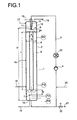
- the reactor 1 which can be used in the process according to the invention comprises generally a pressure-stable reactor body 2 and at least a circulation line 3.
- the cross-sectional shape of the reactor body 2 is in principle for the feasibility of the invention Procedure is not critical and can be triangular, quadrangular, square, rectangular, diamond-shaped, trapezoidal, pentagonal, hexagonal, polygonal, elliptical or circular, preferably it is circular.
- the circulation line 3 can be in the circulation line 3 also one or more heat exchangers 12 for heating and / or cooling the reaction liquid.
- the withdrawal of the reaction liquid can be done in any Height of the reactor body 2 take place, preferably the reaction liquid a calming zone at the bottom taken from the reactor body 2.
- a pump 4 capable of gas / liquid mixtures to pump, for example a side channel pump.
- the dispersed content of the removed reaction liquid Gas bubbles generally depend on the place of withdrawal, it is generally in the high flow areas of the reactor much higher than in the low-flow zone at the bottom End of the reactor, i.e. below the baffle where it is practical can be neglected.
- the nozzle 5 is in the upper part of the reactor body, preferably in the head space 10 filled with reaction gases, so that their nozzle tip in the operating state in the area or below the liquid level, however, above one of the nozzle 5 assigned guide organ 6 is located.
- any suitable for generating a liquid jet Nozzle construction can be used in a particularly preferred
- the embodiment of the method according to the invention is Nozzle 5 designed as a two-component nozzle with which the reaction gas sucked in by the liquid jet generated in the nozzle, in this mixed in with this in the reaction liquid Form of fine gas bubbles is dispersed.
- the lead organ 6 the same cross-sectional shape as the reactor body 2 is advantageous circular And is in the case of the simplest design of the method according to the invention preferably in the central position in the interior of the reactor body via conventional in itself Fasteners attached.
- the shape of the guide organ 6 corresponds to that of an open pipe, which is why in the following is also referred to as a push-in tube.
- the guide element 6 is advantageous with respect to the nozzle 5 in the reactor body arranged so that the nozzle tip 11 is in the center, in an approximately concentric position, preferably exactly concentric position, with respect to the inner cross-sectional area of the guide organ 6 is located.
- the upper end of the insertion tube 6 is advantageously located below the liquid level 9 the reaction liquid at a distance a from the nozzle tip 11.
- the Distance a can depend on the energy input from the Nozzle 5 generated liquid jet can be varied, in general it is 0.1 to 0.8 times, preferably that 0.2 to 0.4 times the inside diameter of the reactor.
- the bottom end the insertion tube 6 is generally at a distance b above the reactor floor 13 or in the case of the preferred Use of a deflection device 7, for example as Baffle plate can be configured at a distance b from this Deflection device 7.
- the size of the distance b can vary widely Ranges vary, and should only be sufficiently large be so that the liquid flow unhindered the insertion tube 7 can leave. In general, the distance b is 0.15 to 1.2 times, preferably 0.3 to 0.6 times the Reactor internal diameter.
- the deflection device 7 is expediently in one installed a certain distance from the reactor floor 13, this In principle, any distance can be chosen.
- the space between the deflection device 7 and the reactor base 13 also filled with reaction liquid and stands with the Reaction liquid above the deflection device 7, e.g. about a passage between the deflection device 7 and the wall of the reactor body 2 or through passages in the deflection device 7 in intimate contact.
- That in the insertion tube 6 is dimensioned so that the ratio from its inner cross-sectional area to the entire inner cross-sectional area of the reactor body 2, which results from the inside diameter D calculated, generally 0.03 to 0.6, preferably 0.06 to 0.4 and particularly preferably 0.1 to 0.36.
- their Inner cross-sectional area designed so that the ratio of the Sum of the internal cross-sectional areas of these insertion tubes 6 total internal cross-sectional area of the reactor body 2 in the aforementioned areas.
- the ratio of the length L of the insertion tube 6 to the inside diameter d is in generally 3 to 40, preferably 4 to 20 and particularly preferred 6 to 12.
- the gaseous reactants i.e. the synthesis gas and, if applicable gaseous olefins, and if desired this gaseous Inert gases mixed with reactants but contained therein, as well as the liquid reactants, ie the olefin, if appropriate in liquefied form and catalyst solution, and if desired, solvents for the hydroformylation reaction can in principle the reactor 1 at any point of the Reactor 1 are supplied.
- the gaseous ones Reactants introduced below the baffle plate 7 (stream 14).
- Gaseous inflows can e.g. but also in the headspace 10, and initiated at various points along the reactor are as indicated by streams 15 and 16. This gains importance especially when it comes to the gaseous Streaming is stripping gas.
- the liquid phase is preferred to the reactor as a partial stream (Stream 21) taken from the pump circuit (3). Other places are also conceivable.
- the gaseous phase becomes the reactor preferably taken from the head space (10) via stream (11). Other options, e.g. below the baffle plate (17), are also conceivable.
- level H remains constant.
- the volume of the drained Liquid is only replaced by gas.
- the gas is sucked out of the headspace via the nozzle and through the downward-pointing one Current carried away. This way in the insertion tube Downward-moving gas rises again in the gap up.
- the nozzle (5) draws gas from the head space as long as until the liquid level touches the nozzle mouth.
- the reactor is able to internally pump gas in the cycle.
- the Baffle plate (17) suppresses the entrainment of gas bubbles into the external pump circuit.
- Prerequisite for the formation of the two-phase circulation flow is that the flow velocity in the insert tube is greater is the rate of ascent of the dispersed gas phase.
- the internally circulated liquid flow is many times over larger than the volume flow of the jet.
- the internally promoted circulating gas flow is a multiple of that from the outside supplied gas flows are. Concentration and temperature gradients this makes them very strong in the liquid phase reduced.
- the reactor can thus be in the entire volume the cheapest to achieve maximum selectivity Conditions are operated.
- reaction conditions of the hydroformylation or aminating hydroformylation are from the specialist literature well known.
- B. Cornils in J. Falbe, New Syntheses with Carbon Monoxide, Springer Verlag, Berlin [1980] Pp. 1-181.
- the invention Hydroformylation or aminating hydroformylation to be carried out as with M. Beller, B. Cornils, C.D. Frohning, C.W. Kohlpainter, J. Mol. Catal. A, 104 (1995) 17-85 performed.
- hydroformylatable olefins are suitable as starting materials, in particular aliphatic olefins with 2 to 20 C atoms, preferably ⁇ -olefins or internal linear olefins with 2 or 4 bis 20 carbon atoms.
- the system could optionally be operated with a mechanically stirred Autoclave (R) as a reactor or with one according to the invention using reactor (G) are operated.
- the autoclave behaves like in an ideally mixed stirred tank reactor.
- olefin or CO / H 2 mixture is fed into the calysator + high-boiler recycle stream and, alternatively, via line (3) either via line (5) into the gas circulation reactor (G) to be used according to the invention or into the stirred tank reactor (R) initiated.
- the hydroformylation output from the reactor was via line (6/9 or (8/9) after relaxation and separation of the liquid Phase of excess synthesis gas in the pressure cutter (A) via line 10 of a distillative workup (consisting of Flash (F) and Sambay evaporator (D)) supplied.
- the swamp out the distillative removal was via line 15 in the hydroformylation stage recycled.
- Via the lines 11 the exhaust gas via line 12 the unreacted olefins and the resulting aldehydes are withdrawn via line 14.
- a continuous experiment was carried out in a gas circulation reactor (G) to be used according to the invention with a total volume of 4.35 l.
- the gas circulation reactor accounts for 3.6 l and the pump circulation 0.75 l. Due to the large circulation volume, the pumping circuit must be counted among the active reactor volumes.
- the catalyst-containing bottoms were returned to the reactor via line 15.
- the rhodium concentration in the reactor was approximately 120 ppm.
- the ligand / rhodium ratio was 120: 1 (mol / mol).
- the high boilers formed under the reaction conditions were used as solvents.
- CO / H 2 was used in a molar ratio of 1: 1.
- the pressure (20bar) and the temperature (105 ° C) were kept constant.
- a circulation rate of 145 kg / h was conveyed into the reactor (G) by means of a pump through line (7) via a nozzle with a diameter of 1.8 mm.
- the gas content in the reactor was set to 10%, which corresponds to a gas volume of 0.345 l, and was kept constant.
- the desired selectivity to the linear isomer was achieved by varying the CO / H 2 ratio in the fresh gas.
- the load was 450 g / (h propylene (99.3%, remainder propane). After starting up the plant, a propylene conversion of 84% was reached a selectivity to aldehydes of 95% with an n content of 87% achieved.
- the RZA was based on the total volume 140.5 g / (h).
- a circulation rate of 145 kg / h was conveyed into the reactor through line (7) using a pump.
- the gas content in the reactor was set at 2% and kept constant.
- the gas volume was only about 0.07 l.
- the gas content based on the total volume was thus about 6% smaller than in Example 1.
- the desired selectivity to the linear isomer was achieved by varying the CO / H 2 ratio in the fresh gas.
- the load was 450 g / h of propylene (99.3%, remainder propane). After starting up the system, the same propylene conversion as measured in Example 1 and with 95% also the same selectivity to aldehydes. Despite the lesser Gas content, the CO partial pressure did not change and the n share of 87% was reached again.
- the load was 250 g / h propene (99.3%, remainder propane).
- the RZA was due to the large, uncontrollable Gas content only 125 g (1h).
Landscapes
- Chemical & Material Sciences (AREA)
- Organic Chemistry (AREA)
- Chemical Kinetics & Catalysis (AREA)
- Dispersion Chemistry (AREA)
- Organic Low-Molecular-Weight Compounds And Preparation Thereof (AREA)
- Low-Molecular Organic Synthesis Reactions Using Catalysts (AREA)
- Physical Or Chemical Processes And Apparatus (AREA)
Claims (10)
- Procédé pour la fabrication d'aldéhydes et/ou d'alcools ou d'amines par la transformation d'oléfines en phase liquide avec du monoxyde de carbone et de l'hydrogène, dans lequel une partie de ces gaz est dispersée sous forme de bulles de gaz dans le liquide réactionnel et une autre partie est dissoute dans le liquide réactionnel, en présence ou en l'absence d'une amine primaire ou secondaire et en présence de complexes carbonyliques de cobalt, rhodium, palladium ou ruthénium dissous de façon homogène dans le liquide réactionnel, avec un ligand contenant du phosphore, de l'arsenic, de l'antimoine ou de l'azote, à température relevée et à une pression de 1 à 100 bar, caractérisé en ce que l'on effectue la transformation dans un réacteur tubulaire disposé verticalement, comprenant un corps de réacteur et au moins une conduite de circulation, on amène une partie du liquide réactionnel en continu, par la conduite de circulation au moins à une buse disposée dans la partie supérieure du corps de réacteur à laquelle sont affectés un organe de guidage ouvert en haut et en bas, limité par des parois parallèles à l'intérieur du réacteur, ainsi qu'une plaque déflectrice située en dessous de l'ouverture inférieure de l'organe de guidage, et en ce qu'avec cette bues on produit dans cet organe de guidage un écoulement de liquide dirigé vers le bas contenant des bulles de gaz dispersées qui, après avoir quitté l'organe de guidage, est dévié en un courant s'écoulant vers le haut dans l'espace intermédiaire entre la paroi de l'organe de guidage et la paroi du corps de réacteur, et à l'extrémité supérieure de l'organe de guidage, une aspiration du jet de la buse affectée à l'organe de guidage est effectuée dans l'organe de guidage.
- Procédé selon la revendication 1, caractérisé en ce que l'on effectue l'hydroformylation dans un réacteur 1, comprenant le corps de réacteur 2 et au moins une conduite de circulation 3 ainsi que des dispositifs d'amenée et de dérivation pour les réactifs et le produit de la réaction, et l'on prélève du corps de réacteur 2, par au moins une conduite de circulation 3, en continu une partie du liquide réactionnel et on l'amène au moins à une buse 5 située dans la partie supérieure du corps de réacteur 2, et en ce que l'on produit au moins un jet qui produit un écoulement dirigé vers le bas dans au moins un organe de guidage 6 monté à l'intérieur du réacteur, lequel, après impact sur au moins un dispositif de déviation 7 en forme de plaque déflectrice, affecté à l'organe de guidage correspondant ou aux organes de guidage 6, est dévié en un courant s'écoulant vers le haut dans l'espace intermédiaire 8 entre corps de réacteur 2 et organe de guidage 6 correspondant, au moins un organe de guidage 6 étant disposé dans le corps de réacteur 2 de façon quea) son extrémité supérieure, à l'état de fonctionnement, se situe en dessous du niveau 9 du liquide réactionnel situé dans le corps de réacteur 2 et au moins une buse 5 affectée à cet organe de guidage 6 se trouve en position approximativement concentrique par rapport à la surface de la section de cet organe de guidage 6,b) son extrémité inférieure est située à distance, au-dessus du fond du réacteur 13 ou au-dessus d'au moins d'un dispositif de déviation 7 affecté à l'organe de guidage 6, et l'organa ou les organes de guidage 6 sont dimensionnés de façon que le rapport entre la surface interne de la section de l'organe de guidage 6 ou de la somme des surfaces internes des sections des organes de guidage 6 et la surface totale interne de la section du corps de réacteur 2 soit de 0,03 à 0,6 et le rapport entre la longueur L d'au moins un organe de guidage 6 affecté à une buse 5 et son diamètre interne d soit de 3 à 40, et qu'au moins une buse 5 soit disposée dans l'espace de tête 10 du corps de réacteur 2 de façon que son sommet 11 se trouve, à l'état de fonctionnement du réacteur, dans la zone ou en dessous du niveau de liquide 8, mais à la distance a, qui est égale à 0,1 à 0,8 fois le diamètre interne du réacteur, de l'extrémité supérieure de cet organe de guidage 6 affecté à cette buse 5.
- Procédé selon les revendications 1 et 2, caractérisé en ce qu'un réacteur 1 est utilisé, dans le corps de réacteur 2 duquel un seul organe de guidage 6 est disposé.
- Procédé selon les revendications 1 à 3, caractérisé en ce que l'on utilise un réacteur 1 dans lequel au moins une conduite de circulation 3 et un dispositif pour transfert thermique 12 sont contenus.
- Procédé selon les revendications 1 à 4, caractérisé en ce que l'on prélève le liquide réactionnel de la partie inférieure du corps de réacteur 2 et on l'amène à la buse 5 par au moins une conduite de circulation 3.
- Procédé selon les revendications 1 à 5, caractérisé en ce que l'on utilise un réacteur 1 dans lequel est monté pour la déviation du jet de liquide provenant d'au moins un organe de guidage 6, à la distance b de l'extrémité inférieure d'un organe de guidage 6, qui est égale à 0,15 à 1,2 fois le diamètre interne du réacteur, au moins un dispositif de déviation 7 en forme d'une plaque déflectrice et, en dessous de la plaque déflectrice, se trouve un espace de stabilisation pour le prélèvement de l'écoulement de liquide pour la conduite de circulation.
- Procédé selon les revendications 1 à 6, caractérisé en ce que l'on utilise un réacteur 1 dont la buse ou les buses 5 sont conçues en tant que buses binaires.
- Procédé selon les revendications 1 à 7, caractérisé en ce que l'on hydroformyle, avec hydrogénation, une oléfine en présence d'un complexe constitué d'une combinaison carbonylique de cobalt et d'un ligand contenant du phosphore, dissous de façon homogène dans le liquide réactionnel, en tant que catalyseur à une température de 160 à 200°C et à une pression de 50 à 100 bar, en l'aldéhyde ou l'alcool ou le mélange alcool/aldéhyde correspondant.
- Procédé selon les revendications 1 à 7, caractérisé en ce que l'on hydroformyle une oléfine, en présence d'un complexe carbonylique de rhodium ou ruthénium avec un ligand contenant du phosphore, de l'arsenic ou de l'antimoine en tant que catalyseur à une température de 60 à 130°C et à une pression de 1 à 50 bar, en l'aldéhyde correspondant.
- Procédé selon les revendications 1 à 7, caractérisé en ce que l'on hydroformyle, avec amination, une oléfine en présence d'un complexe carbonylique de rhodium, palladium ou ruthénium dissous de façon homogène dans le milieu de réaction, avec un ligand contenant du phosphore, de l'arsenic ou de l'antimoine, en tant que catalyseur et en présence d'une amine C2 à C12 primaire ou d'une amine C2 à C24 secondaire, en l'amine primaire, secondaire ou tertiaire correspondante, à une température de 60 à 150°C et à une pression de 1 à 50 bar.
Applications Claiming Priority (3)
| Application Number | Priority Date | Filing Date | Title |
|---|---|---|---|
| DE19836807 | 1998-08-14 | ||
| DE19836807A DE19836807A1 (de) | 1998-08-14 | 1998-08-14 | Verfahren zur Herstellung von Aldehyden und/oder Alkoholen oder Aminen |
| PCT/EP1999/005967 WO2000009467A1 (fr) | 1998-08-14 | 1999-08-13 | Procede de preparation d'aldehydes et/ou d'alcanols ou d'amines |
Publications (2)
| Publication Number | Publication Date |
|---|---|
| EP1114017A1 EP1114017A1 (fr) | 2001-07-11 |
| EP1114017B1 true EP1114017B1 (fr) | 2003-03-19 |
Family
ID=7877481
Family Applications (1)
| Application Number | Title | Priority Date | Filing Date |
|---|---|---|---|
| EP99942870A Expired - Lifetime EP1114017B1 (fr) | 1998-08-14 | 1999-08-13 | Procede de preparation d'aldehydes et/ou d'alcanols ou d'amines |
Country Status (11)
| Country | Link |
|---|---|
| US (1) | US6642420B1 (fr) |
| EP (1) | EP1114017B1 (fr) |
| JP (1) | JP2002522518A (fr) |
| KR (1) | KR100580423B1 (fr) |
| CN (1) | CN1165506C (fr) |
| AT (1) | ATE234802T1 (fr) |
| DE (2) | DE19836807A1 (fr) |
| ES (1) | ES2194500T3 (fr) |
| MY (1) | MY124357A (fr) |
| TW (1) | TW541298B (fr) |
| WO (1) | WO2000009467A1 (fr) |
Cited By (1)
| Publication number | Priority date | Publication date | Assignee | Title |
|---|---|---|---|---|
| US11542935B2 (en) | 2019-11-06 | 2023-01-03 | Pfeiffer Vacuum Gmbh | Gas recirculation device and system having such a device |
Families Citing this family (50)
| Publication number | Priority date | Publication date | Assignee | Title |
|---|---|---|---|---|
| DE10008903A1 (de) | 2000-02-25 | 2001-09-06 | Degussa | Verfahren zur Herstellung von Malonsäurediestern in einem Reaktor mit innen liegenden Wärmeaustauschern |
| JP3864669B2 (ja) * | 2000-05-08 | 2007-01-10 | 三菱化学株式会社 | ヒドロホルミル化方法 |
| US7034062B2 (en) * | 2001-05-25 | 2006-04-25 | BP Exploration Operatiing Company Limited | Fischer-tropsch process |
| DE10201676A1 (de) * | 2002-01-17 | 2003-07-31 | Basf Ag | Verfahren zur Hydroformylierung von Olefinen mit 2 bis 6 Kohlenstoffatomen |
| US6908601B2 (en) | 2002-02-08 | 2005-06-21 | The Boc Group, Inc. | Method for the production of nitrogen trifluoride |
| DE10206132A1 (de) * | 2002-02-14 | 2003-08-21 | Basf Ag | Reaktorkaskade aus Haupt- und Nachreaktor |
| DE60304034T2 (de) | 2002-03-11 | 2006-10-12 | Union Carbide Chemicals & Plastics Technology Corp., Danbury | Bisphosphit-ligande für carbonylierungsverfahren |
| JP2006503086A (ja) | 2002-10-15 | 2006-01-26 | ユニオン・カーバイド・ケミカルズ・アンド・プラスティックス・テクノロジー・コーポレイション | ビス−キレート化配位子及びカルボニル化方法におけるその使用 |
| KR20060096433A (ko) * | 2003-10-21 | 2006-09-11 | 바스프 악티엔게젤샤프트 | 알데히드의 연속식 제조 방법 |
| DE10357718A1 (de) | 2003-12-09 | 2005-07-21 | Basf Ag | Verfahren zur Herstellung von Tricyclodecandialdehyd |
| ES2466644T3 (es) * | 2004-11-15 | 2014-06-10 | The Procter & Gamble Company | Composición detergente líquida para una mejor limpieza de grasa a bajas temperaturas |
| DE102004058888A1 (de) * | 2004-12-06 | 2006-06-08 | Basf Ag | Verfahren zur Herstellung von N,N-Dimethylacetamid (DMAC) |
| WO2008147129A1 (fr) | 2007-05-29 | 2008-12-04 | Lg Chem, Ltd. | Procédé d'hydroformylation d'oléfines et appareil mettant en oeuvre ledit procédé |
| DE102008041652A1 (de) * | 2008-08-28 | 2010-03-04 | Evonik Oxeno Gmbh | Vorrichtung und Verfahren für die kontinuierliche Umsetzung einer Flüssigkeit mit einem Gas |
| KR101291015B1 (ko) * | 2008-11-25 | 2013-07-30 | 주식회사 엘지화학 | 올레핀의 하이드로포밀화 반응장치 및 이를 이용하는 하이드로포밀화 방법 |
| KR101206214B1 (ko) * | 2009-01-16 | 2012-12-03 | 주식회사 엘지화학 | 올레핀으로부터의 알코올을 제조하는 시스템 |
| KR101278375B1 (ko) | 2010-01-18 | 2013-07-05 | 주식회사 엘지화학 | 올레핀 유래 알데히드로부터 알코올로의 변환방법 및 이에 사용되는 반응 장치 |
| KR101342741B1 (ko) | 2010-03-09 | 2013-12-19 | 주식회사 엘지화학 | 반응효율이 뛰어난 올레핀의 하이드로포밀화 방법 |
| KR101298343B1 (ko) * | 2010-05-04 | 2013-08-20 | 주식회사 엘지화학 | 올레핀의 하이드로포밀화 반응장치 및 이를 이용하는 하이드로포밀화 방법 |
| KR101411133B1 (ko) * | 2010-05-25 | 2014-06-23 | 주식회사 엘지화학 | 반응 선택성이 우수한 올레핀의 하이드로포밀화 방법 |
| CN102826970B (zh) * | 2011-06-17 | 2015-08-19 | 中国石油化工股份有限公司 | 一种低碳烯烃氢甲酰化二段反应方法和装置 |
| CN102826975B (zh) * | 2011-06-17 | 2015-08-19 | 中国石油化工股份有限公司 | 一种丙烯氢甲酰化反应制备丁醛的方法 |
| MY172695A (en) | 2012-04-12 | 2019-12-10 | Basf Se | Method for replenishing the catalyst in continuous hydroformylation |
| US8889917B2 (en) | 2012-04-12 | 2014-11-18 | Basf Se | Method of supplementing the catalyst in continuous hydroformylation |
| KR101403823B1 (ko) * | 2013-02-13 | 2014-06-03 | 주식회사 엘지화학 | 올레핀으로부터의 알코올을 제조하는 장치 |
| KR101448374B1 (ko) * | 2013-02-26 | 2014-10-07 | 주식회사 엘지화학 | 반응 선택성이 우수한 올레핀의 하이드로포밀화 방법 |
| CN104513143A (zh) * | 2013-09-26 | 2015-04-15 | 陶氏技术投资有限责任公司 | 加氢甲酰化方法 |
| JP2016540780A (ja) * | 2013-12-19 | 2016-12-28 | ダウ テクノロジー インベストメンツ リミティド ライアビリティー カンパニー | ヒドロホルミル化プロセス |
| PL3319951T3 (pl) | 2015-07-10 | 2022-02-28 | Basf Se | Sposób hydroformylowania 2-podstawionych butadienów oraz wytwarzania ich produktów pochodnych, w szczególności ambroksu |
| WO2017064064A1 (fr) | 2015-10-12 | 2017-04-20 | Basf Se | Procédé d'hydroformylation pour produire des dérivés 1,6-disubstitués d'hexane |
| TW201726242A (zh) * | 2015-12-22 | 2017-08-01 | 巴斯夫歐洲公司 | 圓柱形反應器及其用於連續氫甲醯化反應的用途 |
| CN106118883B (zh) * | 2016-06-29 | 2020-04-21 | 广西壮族自治区林业科学研究院 | 一种樟树精油浸提装置及应用 |
| TW201840362A (zh) | 2016-11-08 | 2018-11-16 | 美商陶氏科技投資有限公司 | 使去活化的氫甲醯化催化劑溶液再生的方法 |
| TW201840363A (zh) | 2016-11-08 | 2018-11-16 | 美商陶氏科技投資有限公司 | 處理氫甲醯化催化劑溶液之方法 |
| TWI758353B (zh) | 2016-11-08 | 2022-03-21 | 美商陶氏科技投資有限公司 | 使去活化的氫甲醯化催化劑溶液再生的方法 |
| JP2020523297A (ja) | 2017-06-13 | 2020-08-06 | ビーエーエスエフ ソシエタス・ヨーロピアBasf Se | 1,6−ヘキサンジオール誘導体を製造するためのヒドロホルミル化方法 |
| TWI788364B (zh) * | 2017-06-23 | 2023-01-01 | 美商陶氏科技投資有限公司 | 氫甲醯化反應製程 |
| CN107469736A (zh) * | 2017-10-12 | 2017-12-15 | 重庆农药化工(集团)有限公司 | 可调节反应压力的反应釜及可调压反应釜系统 |
| US10589249B2 (en) * | 2018-04-27 | 2020-03-17 | Evonik Operations Gmbh | Apparatus for controlling the temperature of a reactor |
| EP3852914A1 (fr) | 2018-09-17 | 2021-07-28 | Basf Se | Procédé et appareil pour réaliser une réaction chimique sous pression élevée |
| CN110201611B (zh) * | 2019-05-30 | 2021-11-23 | 河南能源化工集团研究总院有限公司 | 一种用于烯烃氢甲酰化的三相流反应装置及其操作方法 |
| CN112827433A (zh) * | 2019-11-25 | 2021-05-25 | 南京延长反应技术研究院有限公司 | 一种由烯烃羰基化制备异构醛的智能强化反应系统及工艺 |
| CN112830870A (zh) * | 2019-11-25 | 2021-05-25 | 南京延长反应技术研究院有限公司 | 一种由烯烃羰基化制备异构醛的强化反应系统及工艺 |
| US12281063B2 (en) | 2020-02-11 | 2025-04-22 | Basf Se | Low-pressure hydroformylation of diisobutene |
| CN114177876A (zh) * | 2020-09-15 | 2022-03-15 | 上海睿碳能源科技有限公司 | 一种喷射环流反应器及其应用 |
| CN114177875A (zh) * | 2020-09-15 | 2022-03-15 | 上海睿碳能源科技有限公司 | 一种喷射环流反应器及其应用 |
| US20230406802A1 (en) * | 2020-12-22 | 2023-12-21 | Dow Technology Investments Llc | Hydroformylation reaction processes |
| FR3117891B1 (fr) * | 2020-12-23 | 2024-12-20 | Ifp Energies Now | Reacteur gaz/liquide d’oligomerisation comprenant une conduite centrale |
| CN114029026A (zh) * | 2021-12-08 | 2022-02-11 | 上海市安装工程集团有限公司 | 一种循环加氢反应器 |
| WO2025195907A1 (fr) | 2024-03-22 | 2025-09-25 | Basf Se | Dispositif et procédé de réaction d'un liquide avec un autre fluide |
Family Cites Families (13)
| Publication number | Priority date | Publication date | Assignee | Title |
|---|---|---|---|---|
| GB1511961A (en) * | 1976-03-12 | 1978-05-24 | Ucb Sa | Process for the production of methyl formate |
| DE2645780C2 (de) | 1976-10-09 | 1982-10-07 | Basf Ag, 6700 Ludwigshafen | Verfahren zum Begasen einer Flüssigkeit in einem Umlaufreaktor und zum Verhindern des Entmischens von nicht abreagiertem Gas aus der Flüssigkeit |
| US4277627A (en) | 1977-01-25 | 1981-07-07 | Union Carbide Corporation | Hydroformylation process |
| DE2810644A1 (de) | 1978-03-11 | 1979-09-13 | Basf Ag | Verfahren zur hydroformylierung von olefinen |
| DE3206661A1 (de) | 1982-02-25 | 1983-09-01 | Basf Ag, 6700 Ludwigshafen | Verfahren zur vermeidung einer explosiblen gasphase bei gas/fluessig-reaktionen |
| DE3220858A1 (de) * | 1982-06-03 | 1983-12-08 | Basf Ag, 6700 Ludwigshafen | Verfahren zur hydroformylierung olefinisch ungesaettigter verbindungen |
| US4593127A (en) | 1985-01-11 | 1986-06-03 | Union Carbide Corporation | Hydroformylation process |
| DE3625261A1 (de) | 1986-07-25 | 1988-02-04 | Basf Ag | Verfahren zur kontinuierlichen hydroformylierung olefinisch ungesaettigter verbindungen |
| GB2222098B (en) | 1988-08-24 | 1992-03-18 | Exxon Research Engineering Co | Improvements in and relating to contacting of plural distinct fluid phases |
| JP2893902B2 (ja) | 1989-10-19 | 1999-05-24 | 三菱化学株式会社 | オレフィンのヒドロホルミル化法 |
| US5367106A (en) | 1993-09-20 | 1994-11-22 | Hoechst Celanese Corporation | Coupled secondary oxo reaction system |
| DE4427428A1 (de) | 1994-08-03 | 1996-02-29 | Basf Ag | Verfahren zur Herstellung von Aldehyden |
| US5789625A (en) * | 1995-12-06 | 1998-08-04 | Union Carbide Chemicals & Plastics Technology Corporation | Metal-ligand complex catalyzed processes |
-
1998
- 1998-08-14 DE DE19836807A patent/DE19836807A1/de not_active Withdrawn
-
1999
- 1999-08-13 DE DE59904660T patent/DE59904660D1/de not_active Expired - Lifetime
- 1999-08-13 AT AT99942870T patent/ATE234802T1/de not_active IP Right Cessation
- 1999-08-13 JP JP2000564922A patent/JP2002522518A/ja active Pending
- 1999-08-13 KR KR1020017001862A patent/KR100580423B1/ko not_active Expired - Fee Related
- 1999-08-13 ES ES99942870T patent/ES2194500T3/es not_active Expired - Lifetime
- 1999-08-13 CN CNB998096792A patent/CN1165506C/zh not_active Expired - Lifetime
- 1999-08-13 EP EP99942870A patent/EP1114017B1/fr not_active Expired - Lifetime
- 1999-08-13 US US09/762,425 patent/US6642420B1/en not_active Expired - Lifetime
- 1999-08-13 WO PCT/EP1999/005967 patent/WO2000009467A1/fr not_active Ceased
- 1999-08-14 MY MYPI99003495A patent/MY124357A/en unknown
- 1999-08-16 TW TW088113988A patent/TW541298B/zh not_active IP Right Cessation
Cited By (1)
| Publication number | Priority date | Publication date | Assignee | Title |
|---|---|---|---|---|
| US11542935B2 (en) | 2019-11-06 | 2023-01-03 | Pfeiffer Vacuum Gmbh | Gas recirculation device and system having such a device |
Also Published As
| Publication number | Publication date |
|---|---|
| KR100580423B1 (ko) | 2006-05-16 |
| WO2000009467A1 (fr) | 2000-02-24 |
| DE19836807A1 (de) | 2000-02-17 |
| KR20010072453A (ko) | 2001-07-31 |
| EP1114017A1 (fr) | 2001-07-11 |
| JP2002522518A (ja) | 2002-07-23 |
| TW541298B (en) | 2003-07-11 |
| US6642420B1 (en) | 2003-11-04 |
| CN1312785A (zh) | 2001-09-12 |
| CN1165506C (zh) | 2004-09-08 |
| MY124357A (en) | 2006-06-30 |
| DE59904660D1 (de) | 2003-04-24 |
| ES2194500T3 (es) | 2003-11-16 |
| ATE234802T1 (de) | 2003-04-15 |
Similar Documents
| Publication | Publication Date | Title |
|---|---|---|
| EP1114017B1 (fr) | Procede de preparation d'aldehydes et/ou d'alcanols ou d'amines | |
| EP1204624B1 (fr) | Procede continu d'hydroformulation d'olefines ayant 6 a 20 atomes de carbone | |
| EP1669337B1 (fr) | Procédé pour la fabrication d'alcools à partir d'oléfines par hydroformylation et hydrogenation | |
| EP1106596B1 (fr) | Procédé pour la mise en oeuvre de condensations aldoliques à l'aide de réactions catalysées multiphasiques | |
| EP1106594B1 (fr) | Procédé d'hydroformylation d'oléfines | |
| EP1595596B1 (fr) | Réacteur avec un distributeur pour gaz/liquide avec un mélangeur statique | |
| EP1586372B1 (fr) | Alkoxylation dans un réacteur capillaire ayant une microstructure | |
| EP1057524A2 (fr) | Procédé de réalisation des réactions catalysées multiphasiques, specifiquement hydroformylations | |
| EP1231198B1 (fr) | Hydroformylation | |
| DE3739064A1 (de) | Hydroformylierungsverfahren unter verwendung niedrig fluechtiger phosphorliganden | |
| DE19925385A1 (de) | Verfahren zur katalytischen Durchführung von Mehrphasenreaktionen, insbesondere Vinylierungen von Carbonsäuren | |
| EP3071542B1 (fr) | Procédé d'hydroformylation d'oléfines | |
| EP2125611B1 (fr) | Réacteur et procédé de préparation de sulfure d'hydrogène | |
| EP3846927B1 (fr) | Réacteur destiné à la mise en oeuvre d'une réaction entre deux fluides non miscibles de densité différente | |
| EP3301084B1 (fr) | Procédé de fabrication continu des aldéhydes 2-méthylènés | |
| EP2836474A1 (fr) | Procédé pour compléter le catalyseur lors de l'hydroformylation continue | |
| EP3847151B1 (fr) | Procédé continu pour préparer un composé carbonylé optiquement actif par hydrogénation asymétrique | |
| EP4155288B1 (fr) | Procédé de commande améliorée des rapports d'isomères dans les hydroformylations | |
| DE1938102C (de) | Verfahren zur Herstellung von Aldehyden und Alkoholen nach dem Oxo Verfahren | |
| EP3846929B1 (fr) | Réacteur destiné à la mise en oeuvre d'une réaction biphasique gaz/liquide à haute pression avec un milieu moussant | |
| EP1016439A1 (fr) | Dispositif pour effectuer des distillations et des réactions catalytiques hétérogènes | |
| WO2025195907A1 (fr) | Dispositif et procédé de réaction d'un liquide avec un autre fluide | |
| EP3846931A1 (fr) | Procédé de mise en oeuvre d'une réaction biphasique gaz/liquide à haute pression | |
| DE2248498C3 (de) | Verfahren zur Herstellung von olefinisch ungesättigten Nitrilen | |
| DE1938102B (de) | Verfahren zur Herstellung von Aldehyden und Alkoholen nach dem Oxo-Verfahren |
Legal Events
| Date | Code | Title | Description |
|---|---|---|---|
| PUAI | Public reference made under article 153(3) epc to a published international application that has entered the european phase |
Free format text: ORIGINAL CODE: 0009012 |
|
| 17P | Request for examination filed |
Effective date: 20010119 |
|
| AK | Designated contracting states |
Kind code of ref document: A1 Designated state(s): AT BE CH CY DE DK ES FI FR GB GR IE IT LI LU MC NL PT SE |
|
| 17Q | First examination report despatched |
Effective date: 20010703 |
|
| GRAG | Despatch of communication of intention to grant |
Free format text: ORIGINAL CODE: EPIDOS AGRA |
|
| GRAG | Despatch of communication of intention to grant |
Free format text: ORIGINAL CODE: EPIDOS AGRA |
|
| GRAH | Despatch of communication of intention to grant a patent |
Free format text: ORIGINAL CODE: EPIDOS IGRA |
|
| GRAH | Despatch of communication of intention to grant a patent |
Free format text: ORIGINAL CODE: EPIDOS IGRA |
|
| GRAA | (expected) grant |
Free format text: ORIGINAL CODE: 0009210 |
|
| AK | Designated contracting states |
Designated state(s): AT BE CH CY DE DK ES FI FR GB GR IE IT LI LU MC NL PT SE |
|
| PG25 | Lapsed in a contracting state [announced via postgrant information from national office to epo] |
Ref country code: IE Free format text: LAPSE BECAUSE OF FAILURE TO SUBMIT A TRANSLATION OF THE DESCRIPTION OR TO PAY THE FEE WITHIN THE PRESCRIBED TIME-LIMIT Effective date: 20030319 Ref country code: GR Free format text: LAPSE BECAUSE OF FAILURE TO SUBMIT A TRANSLATION OF THE DESCRIPTION OR TO PAY THE FEE WITHIN THE PRESCRIBED TIME-LIMIT Effective date: 20030319 |
|
| REG | Reference to a national code |
Ref country code: GB Ref legal event code: FG4D Free format text: NOT ENGLISH |
|
| REG | Reference to a national code |
Ref country code: CH Ref legal event code: EP |
|
| REG | Reference to a national code |
Ref country code: SE Ref legal event code: TRGR |
|
| REG | Reference to a national code |
Ref country code: IE Ref legal event code: FG4D Free format text: GERMAN |
|
| REF | Corresponds to: |
Ref document number: 59904660 Country of ref document: DE Date of ref document: 20030424 Kind code of ref document: P |
|
| GBT | Gb: translation of ep patent filed (gb section 77(6)(a)/1977) |
Effective date: 20030507 |
|
| PG25 | Lapsed in a contracting state [announced via postgrant information from national office to epo] |
Ref country code: DK Free format text: LAPSE BECAUSE OF FAILURE TO SUBMIT A TRANSLATION OF THE DESCRIPTION OR TO PAY THE FEE WITHIN THE PRESCRIBED TIME-LIMIT Effective date: 20030619 |
|
| PG25 | Lapsed in a contracting state [announced via postgrant information from national office to epo] |
Ref country code: PT Free format text: LAPSE BECAUSE OF FAILURE TO SUBMIT A TRANSLATION OF THE DESCRIPTION OR TO PAY THE FEE WITHIN THE PRESCRIBED TIME-LIMIT Effective date: 20030620 |
|
| PG25 | Lapsed in a contracting state [announced via postgrant information from national office to epo] |
Ref country code: LU Free format text: LAPSE BECAUSE OF NON-PAYMENT OF DUE FEES Effective date: 20030813 Ref country code: CY Free format text: LAPSE BECAUSE OF FAILURE TO SUBMIT A TRANSLATION OF THE DESCRIPTION OR TO PAY THE FEE WITHIN THE PRESCRIBED TIME-LIMIT Effective date: 20030813 Ref country code: AT Free format text: LAPSE BECAUSE OF NON-PAYMENT OF DUE FEES Effective date: 20030813 |
|
| PG25 | Lapsed in a contracting state [announced via postgrant information from national office to epo] |
Ref country code: MC Free format text: LAPSE BECAUSE OF NON-PAYMENT OF DUE FEES Effective date: 20030831 Ref country code: LI Free format text: LAPSE BECAUSE OF NON-PAYMENT OF DUE FEES Effective date: 20030831 Ref country code: CH Free format text: LAPSE BECAUSE OF NON-PAYMENT OF DUE FEES Effective date: 20030831 |
|
| REG | Reference to a national code |
Ref country code: IE Ref legal event code: FD4D Ref document number: 1114017E Country of ref document: IE |
|
| REG | Reference to a national code |
Ref country code: ES Ref legal event code: FG2A Ref document number: 2194500 Country of ref document: ES Kind code of ref document: T3 |
|
| ET | Fr: translation filed | ||
| PLBE | No opposition filed within time limit |
Free format text: ORIGINAL CODE: 0009261 |
|
| STAA | Information on the status of an ep patent application or granted ep patent |
Free format text: STATUS: NO OPPOSITION FILED WITHIN TIME LIMIT |
|
| 26N | No opposition filed |
Effective date: 20031222 |
|
| REG | Reference to a national code |
Ref country code: CH Ref legal event code: PL |
|
| PGFP | Annual fee paid to national office [announced via postgrant information from national office to epo] |
Ref country code: ES Payment date: 20150923 Year of fee payment: 17 Ref country code: GB Payment date: 20150901 Year of fee payment: 17 Ref country code: FI Payment date: 20150821 Year of fee payment: 17 |
|
| PGFP | Annual fee paid to national office [announced via postgrant information from national office to epo] |
Ref country code: BE Payment date: 20150828 Year of fee payment: 17 |
|
| PGFP | Annual fee paid to national office [announced via postgrant information from national office to epo] |
Ref country code: IT Payment date: 20150825 Year of fee payment: 17 |
|
| REG | Reference to a national code |
Ref country code: FR Ref legal event code: PLFP Year of fee payment: 18 |
|
| PG25 | Lapsed in a contracting state [announced via postgrant information from national office to epo] |
Ref country code: BE Free format text: LAPSE BECAUSE OF NON-PAYMENT OF DUE FEES Effective date: 20160831 |
|
| GBPC | Gb: european patent ceased through non-payment of renewal fee |
Effective date: 20160813 |
|
| PG25 | Lapsed in a contracting state [announced via postgrant information from national office to epo] |
Ref country code: FI Free format text: LAPSE BECAUSE OF NON-PAYMENT OF DUE FEES Effective date: 20160813 |
|
| PG25 | Lapsed in a contracting state [announced via postgrant information from national office to epo] |
Ref country code: GB Free format text: LAPSE BECAUSE OF NON-PAYMENT OF DUE FEES Effective date: 20160813 |
|
| REG | Reference to a national code |
Ref country code: FR Ref legal event code: PLFP Year of fee payment: 19 |
|
| PG25 | Lapsed in a contracting state [announced via postgrant information from national office to epo] |
Ref country code: IT Free format text: LAPSE BECAUSE OF NON-PAYMENT OF DUE FEES Effective date: 20160813 |
|
| PG25 | Lapsed in a contracting state [announced via postgrant information from national office to epo] |
Ref country code: ES Free format text: LAPSE BECAUSE OF NON-PAYMENT OF DUE FEES Effective date: 20160814 |
|
| REG | Reference to a national code |
Ref country code: ES Ref legal event code: FD2A Effective date: 20180627 |
|
| REG | Reference to a national code |
Ref country code: FR Ref legal event code: PLFP Year of fee payment: 20 |
|
| PGFP | Annual fee paid to national office [announced via postgrant information from national office to epo] |
Ref country code: NL Payment date: 20180824 Year of fee payment: 20 Ref country code: FR Payment date: 20180830 Year of fee payment: 20 |
|
| PGFP | Annual fee paid to national office [announced via postgrant information from national office to epo] |
Ref country code: SE Payment date: 20180827 Year of fee payment: 20 |
|
| PGFP | Annual fee paid to national office [announced via postgrant information from national office to epo] |
Ref country code: DE Payment date: 20181031 Year of fee payment: 20 |
|
| REG | Reference to a national code |
Ref country code: DE Ref legal event code: R071 Ref document number: 59904660 Country of ref document: DE |
|
| REG | Reference to a national code |
Ref country code: NL Ref legal event code: MK Effective date: 20190812 |
|
| REG | Reference to a national code |
Ref country code: SE Ref legal event code: EUG |