EP1114896A1 - System zum Anbringen eines Bewehrungsbandes an einer Stützwand und Einrichtung zur Positionierung des Systems - Google Patents
System zum Anbringen eines Bewehrungsbandes an einer Stützwand und Einrichtung zur Positionierung des Systems Download PDFInfo
- Publication number
- EP1114896A1 EP1114896A1 EP01400010A EP01400010A EP1114896A1 EP 1114896 A1 EP1114896 A1 EP 1114896A1 EP 01400010 A EP01400010 A EP 01400010A EP 01400010 A EP01400010 A EP 01400010A EP 1114896 A1 EP1114896 A1 EP 1114896A1
- Authority
- EP
- European Patent Office
- Prior art keywords
- handles
- loop
- wall
- template
- strip
- Prior art date
- Legal status (The legal status is an assumption and is not a legal conclusion. Google has not performed a legal analysis and makes no representation as to the accuracy of the status listed.)
- Granted
Links
- 230000002787 reinforcement Effects 0.000 title description 6
- 239000000463 material Substances 0.000 claims abstract description 10
- 230000003014 reinforcing effect Effects 0.000 claims abstract description 10
- 238000004804 winding Methods 0.000 claims abstract description 10
- 125000006850 spacer group Chemical group 0.000 claims description 12
- 239000000835 fiber Substances 0.000 claims description 7
- 229920000728 polyester Polymers 0.000 claims description 7
- 239000004698 Polyethylene Substances 0.000 claims description 4
- -1 polyethylene Polymers 0.000 claims description 4
- 229920000573 polyethylene Polymers 0.000 claims description 4
- 229920003023 plastic Polymers 0.000 claims description 3
- 239000004033 plastic Substances 0.000 claims description 3
- 230000015572 biosynthetic process Effects 0.000 claims 1
- 238000004873 anchoring Methods 0.000 description 3
- 230000007797 corrosion Effects 0.000 description 2
- 238000005260 corrosion Methods 0.000 description 2
- 238000009434 installation Methods 0.000 description 2
- 239000007787 solid Substances 0.000 description 2
- 229910001335 Galvanized steel Inorganic materials 0.000 description 1
- 238000009412 basement excavation Methods 0.000 description 1
- 238000010276 construction Methods 0.000 description 1
- 230000008878 coupling Effects 0.000 description 1
- 238000010168 coupling process Methods 0.000 description 1
- 238000005859 coupling reaction Methods 0.000 description 1
- 230000006866 deterioration Effects 0.000 description 1
- 239000008397 galvanized steel Substances 0.000 description 1
- 239000013067 intermediate product Substances 0.000 description 1
- 238000004519 manufacturing process Methods 0.000 description 1
- 239000002184 metal Substances 0.000 description 1
- 238000000465 moulding Methods 0.000 description 1
- 230000001681 protective effect Effects 0.000 description 1
- 238000007493 shaping process Methods 0.000 description 1
Images


Classifications
-
- E—FIXED CONSTRUCTIONS
- E02—HYDRAULIC ENGINEERING; FOUNDATIONS; SOIL SHIFTING
- E02D—FOUNDATIONS; EXCAVATIONS; EMBANKMENTS; UNDERGROUND OR UNDERWATER STRUCTURES
- E02D29/00—Independent underground or underwater structures; Retaining walls
- E02D29/02—Retaining or protecting walls
- E02D29/0225—Retaining or protecting walls comprising retention means in the backfill
- E02D29/0241—Retaining or protecting walls comprising retention means in the backfill the retention means being reinforced earth elements
Definitions
- the invention relates to a system for attaching a reinforcing strip to a wall of a reinforced retaining structure.
- Such works by support are provided in the event of embankment, or even excavation, in the area construction of roads, wharves, highways, buildings and others achievements of the building sector and public works.
- Support structures reinforced with backfill, or cut include a facing wall, usually concrete, and between the solid located at the rear and the facing wall, a specific embankment, made of material granular, reinforced by linear reinforcing bands, extending in a plurality of superimposed horizontal planes.
- the reinforcing strips of reinforcement are fixed to the facing wall via a system of attachment.
- a fastening system comprising a pin winding of the reinforcing strip, mounted in two loops, or handles, of attachment, in plasticized and galvanized steel.
- the two handles are sealed in the facing wall and coupled by a metal connecting rod, embedded in the wall, ensuring good anchoring of the handles in the wall.
- fasteners of this type are at risk corrosion, in particular of the coupling rod of the two handles.
- the present invention proposes to overcome this drawback.
- the invention relates to a system for attaching a strip. of reinforcement to a wall of a reinforced retaining structure, comprising a support for winding the reinforcing strip and two fixing handles for the winding support on the wall, characterized in that the two handles are formed from a loop of non-corrodible material.
- the two handles extend each other continuously.
- the loop of non-corrodible material, partially embedded in the wall, guarantees good anchoring of the handles, without any risk of corrosion.
- the loop is made of plastic material.
- the loop may include a polyester fiber core, which provides the mechanical strength of the strip.
- the loop comprises a polyethylene sheath.
- the wall of the retaining structure, in which the loop of the fastening system is partially embedded, is usually made of concrete.
- the concrete is an alkaline medium which can damage polyester fibers.
- the polyethylene sheath protects the core in polyester fibers.
- the loop is formed from a strip rolled up on itself.
- the handles comprise the two ends of the strip.
- polyester loop at both ends of the band Thanks to this, the risks of deterioration of the fiber core are avoided. polyester loop at both ends of the band.
- the invention also relates to a device for installing the system. of attachment, explained above, to a wall of a retaining structure reinforced, including a loop shaping and training template of the two handles.
- means are provided for positioning the two handles along the template.
- means are provided to ensure the parallelism between two branches of each handle.
- the fastening system of the invention is intended to fasten a strip of reinforcement to a facing wall of a retaining structure, such as that represented in FIG. 1.
- This structure which supports a massif 1, includes, between the facing wall 2 and the solid block 1, a specific embankment 3 reinforced by 4-6 reinforcement strips, which extend in a plurality of planes superimposed.
- the wall 2 is constituted by the assembly of a plurality of panels.
- Each 4-6 reinforcement strip goes back and forth, "zig-zag", between a deflection bar 7-9, located near the block 1, and the facing wall 2, to which it is attached using the fastening system which will now be described.
- the fastening system includes a support 10 for winding an armature strip 4, or "pin", and two handles 11a, 11b for fixing the winding support 10 to the wall 2, projecting from the wall 2.
- the handles 11a, 11b perpendicular to the wall 2 and facing one of the other, are spaced a distance less than the length of the pin 10.
- Each handle 11a (11b) comprises two branches 13a, 14a (13b, 14b) substantially parallel and connected by a curved portion 15a (15b).
- the distance between the two branches 13a, 14a (13b, 14b) of a handle 11a (11b) is substantially equal to the diameter of the pin 10.
- the two handles 11a, 11b are formed from a basic loop 16. This loop 16, laid flat, has a generally oval shape and includes two parallel portions connected between them by two U-shaped connecting portions.
- the two connection portions are raised, the loop 16 thus generally and naturally in the form of a gondola.
- the loop 16 is partially embedded in the wall 2, from which it projects by the two handles 11a, 11b. These are thus extend each other by two loop portions, embedded in the wall 2. Thanks to the fact that the two handles are part of the same piece and are not so not isolated from each other, the loop portions, joining the two handles and embedded in the concrete, secure the fastening system to an interesting portion of the wall of the retaining structure. So the loop portions embedded in the concrete ensure excellent anchoring of handles 11a, 11b in the wall 2.
- the loop 16 is formed from a partially wound strip on itself and whose two ends 17, 18 are welded to the strip.
- the strip is made of non-corrodible plastic material. She understands a soul in polyester fibers, with high mechanical strength, in particular tensile strength, surrounded by a polyethylene protective sheath. The sheath is intended for protect the polyester fiber core from the alkalinity of the concrete in wall 2 and from the aggressiveness of the embankment used.
- the two handles 11a, 11b respectively comprise the two ends 17, 18 of the strip, which are thus outside the wall 2. Thanks to this, the web of the strip does not risk being damaged at the level of the ends 17, 18 due to the alkalinity of the concrete.
- the winding support 10 also called a pin, is a rod cylindrical. It is fixed to the wall 2 by passing through the two handles 11a, 11b. A reinforcing strip 4 is intended to be wrapped around the pin 10, on a half-turn, as shown in FIG. 2.
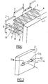
- This device 20 comprises a cylindrical bar 21, substantially of same shape as pin 10, forming template for loop configuration 16 and forming the two handles 11a, 11b.
- Two pairs of flanges, or annular flanges, 22a, 23a, 22b, 23b, intended to position the handles 11a, 11b along the template 21, are mounted on the template 21 and integral with it.
- Each handle 11a (11b) is intended for be blocked laterally, along the template 21, between the two flanges 22a, 23a (22b, 23b) of a pair of flanges, the spacing between the two pairs of flanges 22a, 23a, 22b, 23b thus defining the spacing between the two handles 11a, 11b.
- the laying device 20 also includes two spacers 24a, 24b, integral with the template 21, and two clips 25a, intended to press the handles 11a, 11b against the spacers 24a, 24b in order to ensure the parallelism between the branches 13a, 14a, 13b, 14b, handles 11a, 11b, at least a distance equal to the diameter of the pin 10.
- the spacers 24a, 24b are integral with the template 21. Each spacer 24a (24b) extends between the two flanges 22a, 23a (22b, 23b) of a pair of flanges, below the template 21, as shown in Figure 5.
- the two spacers 24a, 24b being identical, only one will now be described.
- the spacer 24a has the overall shape of a rectangular parallelepiped comprising two lateral bearing surfaces 27a, 28a, parallel to the axis longitudinal of the template 21, and an upper surface providing a cavity 28a for receiving the template 21.
- the distance separating the two bearing surfaces 27a, 28a is substantially equal to the distance between the two branches 13a, 14a handle 11a.
- Each clip 25a comprises two support arms 29a, 30a, elastically deformable, extending from each other and provided with two free ends support curved outwards.
- the two support arms 29a, 30a are intended to press the two arms by their curved free ends 13a, 14a of the handle 11a against the two bearing surfaces 27a, 28a of the spacer 24a, in order to ensure parallelism between the two branches 13a, 14a of the handle 11a and to maintain the loop 16 conformed during the installation of the system of attachment.
- the concrete panels constituting the wall 2 are manufactured by flat molding.
- the device When manufacturing a panel, the device is positioned laying 20 above the mold, the spacers 24a, 24b extending below of the template 21, and it blocks the template 21 in rotation. We then take the loop 16, not yet shaped.
- the loop 16 is conformed by applying it against the upper part of the template 21, between the two flanges 22a, 23a a pair of flanges, and against the bearing surfaces 26a, 27a of the spacer 24a.
- the clip 25a is then placed by straddling it on the template 21, by a vertical downward movement between the two flanges 22a, 23a.
- Both arm 29a, 30a of clip 25a press and hold, by their ends free curved, the two branches 13a, 14a of the handle 11a against the two bearing surfaces 26a, 27a of the spacer 24a, thereby ensuring parallelism between the two branches 13a, 14a.
- the clips 25a block handles 11a, 11b and thus prevent any movement of handles 11a, 11b that either up or down.
- the base band, from which the handles 11a, 11b are formed, was implicitly flexible in the description which has just been made. We could imagine a fastening system using a loop of rigid material or semi-rigid.
Landscapes
- Engineering & Computer Science (AREA)
- Civil Engineering (AREA)
- Structural Engineering (AREA)
- General Life Sciences & Earth Sciences (AREA)
- Mining & Mineral Resources (AREA)
- Paleontology (AREA)
- Environmental & Geological Engineering (AREA)
- General Engineering & Computer Science (AREA)
- Life Sciences & Earth Sciences (AREA)
- Pit Excavations, Shoring, Fill Or Stabilisation Of Slopes (AREA)
- Forms Removed On Construction Sites Or Auxiliary Members Thereof (AREA)
- Tents Or Canopies (AREA)
- Building Environments (AREA)
- Automotive Seat Belt Assembly (AREA)
- Lining Or Joining Of Plastics Or The Like (AREA)
Applications Claiming Priority (2)
| Application Number | Priority Date | Filing Date | Title |
|---|---|---|---|
| FR0000178A FR2803610B1 (fr) | 2000-01-07 | 2000-01-07 | Systeme d'attache d'une bande d'armature a une paroi d'un ouvrage de soutenement et dispositif de pose dudit systeme |
| FR0000178 | 2000-01-07 |
Publications (2)
| Publication Number | Publication Date |
|---|---|
| EP1114896A1 true EP1114896A1 (de) | 2001-07-11 |
| EP1114896B1 EP1114896B1 (de) | 2005-03-16 |
Family
ID=8845691
Family Applications (1)
| Application Number | Title | Priority Date | Filing Date |
|---|---|---|---|
| EP01400010A Expired - Lifetime EP1114896B1 (de) | 2000-01-07 | 2001-01-04 | System zum Anbringen eines Bewehrungsbandes an einer Stützwand und Einrichtung zur Positionierung des Systems |
Country Status (8)
| Country | Link |
|---|---|
| US (1) | US6447212B2 (de) |
| EP (1) | EP1114896B1 (de) |
| JP (1) | JP4544754B2 (de) |
| AT (1) | ATE291126T1 (de) |
| AU (1) | AU780932B2 (de) |
| DE (1) | DE60109334D1 (de) |
| FR (1) | FR2803610B1 (de) |
| TR (1) | TR200100153A3 (de) |
Cited By (6)
| Publication number | Priority date | Publication date | Assignee | Title |
|---|---|---|---|---|
| FR2860811A1 (fr) | 2003-10-13 | 2005-04-15 | Freyssinet Int Stup | Ouvrage en sol renforce et procede pour sa construction |
| FR2874392A1 (fr) * | 2004-08-17 | 2006-02-24 | Dominique Georges Guy Boscher | Systeme modulaire de plaques d'ancrages pour murs de soutenements |
| WO2007102070A3 (en) * | 2006-03-09 | 2007-11-22 | Terre Armee Int | Stabilized soil structure and facing elements for its construction |
| EP2434059A1 (de) | 2010-09-24 | 2012-03-28 | Terre Armée Internationale | Verstärkte Bodenstruktur |
| EP2434060A1 (de) | 2010-09-24 | 2012-03-28 | Terre Armée Internationale | Verstärkte Bodenstruktur |
| RU2544346C2 (ru) * | 2010-11-26 | 2015-03-20 | Терр Армэ Энтернасьональ | Облицовочный элемент с приданной ему сжимаемостью |
Families Citing this family (21)
| Publication number | Priority date | Publication date | Assignee | Title |
|---|---|---|---|---|
| US6854236B2 (en) | 2001-10-11 | 2005-02-15 | Allan Block Corporation | Reinforcing system for stackable retaining wall units |
| US6792731B2 (en) | 2001-10-11 | 2004-09-21 | Timothy A. Bott | Reinforcing system for stackable retaining wall units |
| KR100660356B1 (ko) * | 2004-10-19 | 2006-12-21 | 이정수 | 조립식 보강토 옹벽 지지용 띠형 섬유보강재의 시공방법및 이 시공방법에 사용되는 띠형 섬유보강재 |
| FR2878268B1 (fr) * | 2004-11-25 | 2007-02-09 | Freyssinet Internat Stup Soc P | Ouvrage en sol renforce et elements de parement pour sa construction |
| FR2896520A1 (fr) * | 2006-01-23 | 2007-07-27 | Freyssinet Soc Par Actions Sim | Ouvrage erige devant une paroi preexistante, comportant un parement et un remblai entre la paroi et le parement, et procede pour sa realisation |
| FR2913436B1 (fr) * | 2007-03-05 | 2009-05-29 | Terre Armee Internationale Soc | Ouvrage en sol renforce et elements de renfort pour sa construction |
| US20080292413A1 (en) * | 2007-05-23 | 2008-11-27 | Mateer Stephen A | Cast stone, earthen retaining wall system incorporating geogrid, textile or fabric as the soil reinforcement. |
| TW200932998A (en) * | 2008-01-24 | 2009-08-01 | Ke-Jian Yu | Method of forming retaining wall for water and soil conservation and retaining plates |
| US8579552B2 (en) * | 2008-01-24 | 2013-11-12 | Kei-Chien Yu | Ecological board and its applications |
| US7828498B2 (en) * | 2008-04-02 | 2010-11-09 | Sorheim Daniel R | Connection mechanism for large scale retaining wall blocks |
| FR2939157B1 (fr) * | 2008-12-02 | 2013-02-15 | Terre Armee Int | Ouvrage en sol renforce et elements de parement pour sa construction |
| US20100215442A1 (en) * | 2009-02-26 | 2010-08-26 | Ackerstein Industries | Retaining wall stabilization system |
| FR2948386B1 (fr) | 2009-07-22 | 2011-07-29 | Terre Armee Int | Dispositif de liaison pour un ouvrage en sol renforce, ouvrage et procede associes |
| HRP20140210T1 (hr) * | 2010-03-25 | 2014-04-11 | Terre Armée Internationale | Potporni zid s ojaäśanim elementima za uzemljenje u zasipu |
| US9103089B2 (en) * | 2013-03-15 | 2015-08-11 | Tricon Precast, Ltd. | Loop and saddle connection system and method for mechanically stablized earth wall |
| US20140345220A1 (en) | 2013-05-24 | 2014-11-27 | Francesco Ferraiolo | Anchoring system for concrete panels in a stabilized earth structure |
| FR3010423B1 (fr) | 2013-09-09 | 2016-02-19 | Soletanche Freyssinet | Systeme d'attache sur ancrage geotechnique et ensemble de renfort utilisant une telle attache. |
| US20150078838A1 (en) * | 2013-09-18 | 2015-03-19 | Kenneth Shaw | Horizontal connection for mechanically stabilized earth walls |
| US10161099B2 (en) * | 2014-12-22 | 2018-12-25 | Tricon Precast, Ltd. | Geosynthetic connection systems and methods for mechanically stablized earth walls |
| JP5931307B1 (ja) * | 2016-01-26 | 2016-06-08 | 株式会社山源 | 止水装置 |
| WO2020227398A1 (en) * | 2019-05-07 | 2020-11-12 | E.C. Manufacturing, LLC | Landscaping walls, systems and methods |
Citations (4)
| Publication number | Priority date | Publication date | Assignee | Title |
|---|---|---|---|---|
| US4343571A (en) * | 1978-07-13 | 1982-08-10 | Soil Structures International Limited | Reinforced earth structures |
| WO1984002510A1 (fr) * | 1982-12-21 | 1984-07-05 | Shiraijitsugyo Co Ltd | Elingue en fibre en forme de courroie |
| US5624211A (en) * | 1993-03-31 | 1997-04-29 | Societe Civile Des Brevets Henri C. Vidal | Modular block retaining wall construction and components |
| WO1998006907A1 (en) * | 1996-08-09 | 1998-02-19 | Derrick Ian Peter Price | Soil reinforcement |
Family Cites Families (13)
| Publication number | Priority date | Publication date | Assignee | Title |
|---|---|---|---|---|
| GB1050789A (de) * | 1964-06-04 | 1965-08-27 | ||
| DE2753243A1 (de) * | 1977-11-29 | 1979-06-07 | Bayer Ag | Bewehrung von armierten erdbauwerken |
| JPS55144116A (en) * | 1979-04-28 | 1980-11-10 | Hirose Kozai Sangyo | Flask device for manufacturing concrete block |
| EP0130949A3 (de) * | 1983-06-28 | 1985-11-27 | Luciano Sangiorgio | Betonplatten und Erdverankerungsmittel dafür zum Erstellen einer Verkleidungsmauer mit veränderlicher Linienführung und zum Anbringen der Platten in der Mauerebene, sowie die so erstellte Verkleidungsmauer |
| DE9117119U1 (de) * | 1991-09-25 | 1996-02-01 | Gebr. Philipp GmbH, 63741 Aschaffenburg | Seilschlaufeneinlegeteil für den Verbund von Betonfertigteilen |
| US5507599A (en) * | 1993-03-31 | 1996-04-16 | Societe Civile Des Brevets Henri C. Vidal | Modular block retaining wall construction and components |
| US5568998A (en) * | 1995-02-14 | 1996-10-29 | The Tensar Corporation | Precast wall panel and grid connection device |
| JPH08302693A (ja) * | 1995-05-11 | 1996-11-19 | Maeda Kousen Kk | 補強土工法 |
| CA2182430A1 (en) * | 1995-08-18 | 1997-02-19 | Michael Joseph Cowell | Facing element for a stabilised earth structure |
| JPH1060896A (ja) * | 1996-08-22 | 1998-03-03 | Kyokado Eng Co Ltd | 補強土構造物の壁面構造 |
| FR2773372B1 (fr) * | 1998-01-07 | 2000-03-24 | Freyssinet Int Stup | Systeme d'attache d'une bande d'armature a une paroi d'un ouvrage de soutenement renforce et procede de fabrication de la paroi |
| US6186703B1 (en) * | 1998-03-12 | 2001-02-13 | Shaw Technologies | Mechanical interlocking means for retaining wall |
| US5975810A (en) * | 1998-04-01 | 1999-11-02 | Taylor; Thomas P. | Geo-grid anchor |
-
2000
- 2000-01-07 FR FR0000178A patent/FR2803610B1/fr not_active Expired - Fee Related
-
2001
- 2001-01-04 DE DE60109334T patent/DE60109334D1/de not_active Expired - Lifetime
- 2001-01-04 EP EP01400010A patent/EP1114896B1/de not_active Expired - Lifetime
- 2001-01-04 AT AT01400010T patent/ATE291126T1/de not_active IP Right Cessation
- 2001-01-05 TR TR2001/00153A patent/TR200100153A3/tr unknown
- 2001-01-05 AU AU11085/01A patent/AU780932B2/en not_active Ceased
- 2001-01-08 US US09/756,091 patent/US6447212B2/en not_active Expired - Fee Related
- 2001-01-09 JP JP2001001400A patent/JP4544754B2/ja not_active Expired - Lifetime
Patent Citations (4)
| Publication number | Priority date | Publication date | Assignee | Title |
|---|---|---|---|---|
| US4343571A (en) * | 1978-07-13 | 1982-08-10 | Soil Structures International Limited | Reinforced earth structures |
| WO1984002510A1 (fr) * | 1982-12-21 | 1984-07-05 | Shiraijitsugyo Co Ltd | Elingue en fibre en forme de courroie |
| US5624211A (en) * | 1993-03-31 | 1997-04-29 | Societe Civile Des Brevets Henri C. Vidal | Modular block retaining wall construction and components |
| WO1998006907A1 (en) * | 1996-08-09 | 1998-02-19 | Derrick Ian Peter Price | Soil reinforcement |
Cited By (14)
| Publication number | Priority date | Publication date | Assignee | Title |
|---|---|---|---|---|
| WO2005040506A1 (en) | 2003-10-13 | 2005-05-06 | Freyssinet | Reinforced soil structure and method for constructing it |
| FR2860811A1 (fr) | 2003-10-13 | 2005-04-15 | Freyssinet Int Stup | Ouvrage en sol renforce et procede pour sa construction |
| FR2874392A1 (fr) * | 2004-08-17 | 2006-02-24 | Dominique Georges Guy Boscher | Systeme modulaire de plaques d'ancrages pour murs de soutenements |
| US7850400B2 (en) | 2004-11-25 | 2010-12-14 | Freyssinet International (Stup) | Stabilized soil structure and facing elements for its construction |
| US8152417B2 (en) | 2004-11-25 | 2012-04-10 | Terre Armee Internationale | Stabilized soil structure and facing elements for its construction |
| CN101400861B (zh) * | 2006-03-09 | 2011-01-19 | 泰瑞埃米国际公司 | 加固土结构及其建造中使用的护面构件 |
| EA013729B1 (ru) * | 2006-03-09 | 2010-06-30 | Терр Арме Энтернасьональ | Закрепляющая грунт конструкция и облицовочные элементы для ее изготовления |
| WO2007102070A3 (en) * | 2006-03-09 | 2007-11-22 | Terre Armee Int | Stabilized soil structure and facing elements for its construction |
| HRP20080424B1 (hr) * | 2006-03-09 | 2017-02-10 | Terre Armee Internationale | Stabilizirana struktura tla i elementi za oblaganje za njegovu konstrukciju |
| EP2434059A1 (de) | 2010-09-24 | 2012-03-28 | Terre Armée Internationale | Verstärkte Bodenstruktur |
| EP2434060A1 (de) | 2010-09-24 | 2012-03-28 | Terre Armée Internationale | Verstärkte Bodenstruktur |
| WO2012038549A1 (en) | 2010-09-24 | 2012-03-29 | Terre Armee Internationale | A reinforced soil structure |
| US9080303B2 (en) | 2010-09-24 | 2015-07-14 | Terre Armee Internationale | Reinforced soil structure |
| RU2544346C2 (ru) * | 2010-11-26 | 2015-03-20 | Терр Армэ Энтернасьональ | Облицовочный элемент с приданной ему сжимаемостью |
Also Published As
| Publication number | Publication date |
|---|---|
| FR2803610B1 (fr) | 2002-09-27 |
| JP2001226969A (ja) | 2001-08-24 |
| EP1114896B1 (de) | 2005-03-16 |
| AU1108501A (en) | 2001-07-12 |
| DE60109334D1 (de) | 2005-04-21 |
| AU780932B2 (en) | 2005-04-28 |
| US20010014255A1 (en) | 2001-08-16 |
| TR200100153A2 (tr) | 2001-08-21 |
| FR2803610A1 (fr) | 2001-07-13 |
| TR200100153A3 (tr) | 2001-08-21 |
| ATE291126T1 (de) | 2005-04-15 |
| JP4544754B2 (ja) | 2010-09-15 |
| US6447212B2 (en) | 2002-09-10 |
Similar Documents
| Publication | Publication Date | Title |
|---|---|---|
| EP1114896B1 (de) | System zum Anbringen eines Bewehrungsbandes an einer Stützwand und Einrichtung zur Positionierung des Systems | |
| BE1009023A3 (fr) | Traverses pour voies ferrees de chemin de fer. | |
| EP0188487B1 (de) | Im erdboden verlegtes rohr mit grossem durchmesser | |
| EP2550406B1 (de) | Rückhaltewand mit bewehrter erde | |
| CA2515316C (fr) | Ouvrage en sol renforce et elements de parement pour sa construction | |
| EP0003087A1 (de) | Vorrichtung zur Verbindung von Skelettelementen aus Stahlbeton und Skelette bestehend aus mittels dieser Vorrichtungen verbundenen Elementen | |
| EP0833987B1 (de) | Durchgehend verstärkte trennwand, zugehorige herstellungsverfahren und schalung | |
| WO2015019017A2 (fr) | Dispositif d'etancheite et structure pour element en beton arme comprenant ledit dispositif | |
| FR2948386A1 (fr) | Dispositif de liaison pour un ouvrage en sol renforce, ouvrage et procede associes | |
| EP0767881B1 (de) | Flüssigkeitsrohr | |
| FR2980808A1 (fr) | Boitier d'attente monobloc en matiere plastique et dispositif obtenu avec un tel boitier | |
| EP2283185B1 (de) | Stabilisierungsbewehrung zur verwendung in bewehrten bodenkonstruktionen | |
| FR2706498A1 (fr) | Procédé de réalisation d'un ouvrage d'art voûté sous remblai, aménageant un passage. | |
| EP0952307B1 (de) | Verfahren zur Errichtung einer Struktur unterhalb einer Trägböschung eines Gleises bzw. einer Fahrbahn | |
| BE898692A (fr) | Poutre cintree en beton precontraint ou en beton arme | |
| FR2584440A1 (fr) | Douille de positionnement de tube lors de la coulee de beton arme. | |
| EP1376808A1 (de) | Vorrichtung zur Befestigung eines Kabelführungskanals auf einem Träger und Anordnung mit einem Kanal und einer solchen Vorrichtung | |
| FR2938569A1 (fr) | Mur prefabrique equipe d'un dispositif de mise en place d'un garde-corps | |
| EP1852559B1 (de) | Vorrichtung zur Schalungsverankerung | |
| FR3100257A1 (fr) | Dispositif pour la réalisation d'un mur de soutènement en massif renforcé | |
| FR2605031A1 (fr) | Poutre a deformation plastique controlee. | |
| CH660618A5 (en) | Device for guiding tubes and/or pipes coming out of concrete slabs and its use | |
| FR2657639A1 (fr) | Procede de coffrage d'une paroi en beton arme moulee dans une tranchee et coffrage pour la mise en óoeuvre de ce procede. | |
| FR2806429A1 (fr) | Procede pour renforcer un cable porteur de structure suspendue de genie civil et structure de genie civil comportant un cable porteur renforce | |
| FR2997423A1 (fr) | Dispositif de passage a niveau ameliore |
Legal Events
| Date | Code | Title | Description |
|---|---|---|---|
| PUAI | Public reference made under article 153(3) epc to a published international application that has entered the european phase |
Free format text: ORIGINAL CODE: 0009012 |
|
| AK | Designated contracting states |
Kind code of ref document: A1 Designated state(s): AT BE CH CY DE DK ES FI FR GB GR IE IT LI LU MC NL PT SE TR |
|
| AX | Request for extension of the european patent |
Free format text: AL;LT;LV;MK;RO;SI |
|
| 17P | Request for examination filed |
Effective date: 20020111 |
|
| AKX | Designation fees paid |
Free format text: AT BE CH CY DE DK ES FI FR GB GR IE IT LI LU MC NL PT SE TR |
|
| 17Q | First examination report despatched |
Effective date: 20031008 |
|
| GRAP | Despatch of communication of intention to grant a patent |
Free format text: ORIGINAL CODE: EPIDOSNIGR1 |
|
| GRAS | Grant fee paid |
Free format text: ORIGINAL CODE: EPIDOSNIGR3 |
|
| GRAA | (expected) grant |
Free format text: ORIGINAL CODE: 0009210 |
|
| AK | Designated contracting states |
Kind code of ref document: B1 Designated state(s): AT BE CH CY DE DK ES FI FR GB GR IE IT LI LU MC NL PT SE TR |
|
| PG25 | Lapsed in a contracting state [announced via postgrant information from national office to epo] |
Ref country code: IT Free format text: LAPSE BECAUSE OF FAILURE TO SUBMIT A TRANSLATION OF THE DESCRIPTION OR TO PAY THE FEE WITHIN THE PRESCRIBED TIME-LIMIT;WARNING: LAPSES OF ITALIAN PATENTS WITH EFFECTIVE DATE BEFORE 2007 MAY HAVE OCCURRED AT ANY TIME BEFORE 2007. THE CORRECT EFFECTIVE DATE MAY BE DIFFERENT FROM THE ONE RECORDED. Effective date: 20050316 Ref country code: FI Free format text: LAPSE BECAUSE OF FAILURE TO SUBMIT A TRANSLATION OF THE DESCRIPTION OR TO PAY THE FEE WITHIN THE PRESCRIBED TIME-LIMIT Effective date: 20050316 Ref country code: AT Free format text: LAPSE BECAUSE OF FAILURE TO SUBMIT A TRANSLATION OF THE DESCRIPTION OR TO PAY THE FEE WITHIN THE PRESCRIBED TIME-LIMIT Effective date: 20050316 Ref country code: NL Free format text: LAPSE BECAUSE OF FAILURE TO SUBMIT A TRANSLATION OF THE DESCRIPTION OR TO PAY THE FEE WITHIN THE PRESCRIBED TIME-LIMIT Effective date: 20050316 Ref country code: IE Free format text: LAPSE BECAUSE OF FAILURE TO SUBMIT A TRANSLATION OF THE DESCRIPTION OR TO PAY THE FEE WITHIN THE PRESCRIBED TIME-LIMIT Effective date: 20050316 Ref country code: GB Free format text: LAPSE BECAUSE OF FAILURE TO SUBMIT A TRANSLATION OF THE DESCRIPTION OR TO PAY THE FEE WITHIN THE PRESCRIBED TIME-LIMIT Effective date: 20050316 |
|
| REG | Reference to a national code |
Ref country code: GB Ref legal event code: FG4D Free format text: NOT ENGLISH |
|
| REG | Reference to a national code |
Ref country code: CH Ref legal event code: EP |
|
| REG | Reference to a national code |
Ref country code: IE Ref legal event code: FG4D Free format text: FRENCH |
|
| REF | Corresponds to: |
Ref document number: 60109334 Country of ref document: DE Date of ref document: 20050421 Kind code of ref document: P |
|
| PG25 | Lapsed in a contracting state [announced via postgrant information from national office to epo] |
Ref country code: DK Free format text: LAPSE BECAUSE OF FAILURE TO SUBMIT A TRANSLATION OF THE DESCRIPTION OR TO PAY THE FEE WITHIN THE PRESCRIBED TIME-LIMIT Effective date: 20050616 Ref country code: GR Free format text: LAPSE BECAUSE OF FAILURE TO SUBMIT A TRANSLATION OF THE DESCRIPTION OR TO PAY THE FEE WITHIN THE PRESCRIBED TIME-LIMIT Effective date: 20050616 |
|
| PG25 | Lapsed in a contracting state [announced via postgrant information from national office to epo] |
Ref country code: DE Free format text: LAPSE BECAUSE OF FAILURE TO SUBMIT A TRANSLATION OF THE DESCRIPTION OR TO PAY THE FEE WITHIN THE PRESCRIBED TIME-LIMIT Effective date: 20050617 |
|
| PG25 | Lapsed in a contracting state [announced via postgrant information from national office to epo] |
Ref country code: ES Free format text: LAPSE BECAUSE OF FAILURE TO SUBMIT A TRANSLATION OF THE DESCRIPTION OR TO PAY THE FEE WITHIN THE PRESCRIBED TIME-LIMIT Effective date: 20050627 |
|
| NLV1 | Nl: lapsed or annulled due to failure to fulfill the requirements of art. 29p and 29m of the patents act | ||
| PG25 | Lapsed in a contracting state [announced via postgrant information from national office to epo] |
Ref country code: PT Free format text: LAPSE BECAUSE OF FAILURE TO SUBMIT A TRANSLATION OF THE DESCRIPTION OR TO PAY THE FEE WITHIN THE PRESCRIBED TIME-LIMIT Effective date: 20050907 |
|
| GBV | Gb: ep patent (uk) treated as always having been void in accordance with gb section 77(7)/1977 [no translation filed] |
Effective date: 20050316 |
|
| REG | Reference to a national code |
Ref country code: IE Ref legal event code: FD4D |
|
| PLBE | No opposition filed within time limit |
Free format text: ORIGINAL CODE: 0009261 |
|
| STAA | Information on the status of an ep patent application or granted ep patent |
Free format text: STATUS: NO OPPOSITION FILED WITHIN TIME LIMIT |
|
| PG25 | Lapsed in a contracting state [announced via postgrant information from national office to epo] |
Ref country code: BE Free format text: LAPSE BECAUSE OF NON-PAYMENT OF DUE FEES Effective date: 20060131 Ref country code: FR Free format text: LAPSE BECAUSE OF NON-PAYMENT OF DUE FEES Effective date: 20060131 Ref country code: LI Free format text: LAPSE BECAUSE OF NON-PAYMENT OF DUE FEES Effective date: 20060131 Ref country code: MC Free format text: LAPSE BECAUSE OF NON-PAYMENT OF DUE FEES Effective date: 20060131 Ref country code: LU Free format text: LAPSE BECAUSE OF NON-PAYMENT OF DUE FEES Effective date: 20060131 Ref country code: CH Free format text: LAPSE BECAUSE OF NON-PAYMENT OF DUE FEES Effective date: 20060131 |
|
| 26N | No opposition filed |
Effective date: 20051219 |
|
| REG | Reference to a national code |
Ref country code: CH Ref legal event code: PL |
|
| REG | Reference to a national code |
Ref country code: FR Ref legal event code: ST Effective date: 20060929 |
|
| BERE | Be: lapsed |
Owner name: FREYSSINET INTERNATIONAL (STUP) Effective date: 20060131 |
|
| PG25 | Lapsed in a contracting state [announced via postgrant information from national office to epo] |
Ref country code: SE Free format text: LAPSE BECAUSE OF FAILURE TO SUBMIT A TRANSLATION OF THE DESCRIPTION OR TO PAY THE FEE WITHIN THE PRESCRIBED TIME-LIMIT Effective date: 20050616 |
|
| PG25 | Lapsed in a contracting state [announced via postgrant information from national office to epo] |
Ref country code: TR Free format text: LAPSE BECAUSE OF FAILURE TO SUBMIT A TRANSLATION OF THE DESCRIPTION OR TO PAY THE FEE WITHIN THE PRESCRIBED TIME-LIMIT Effective date: 20050316 |
|
| PG25 | Lapsed in a contracting state [announced via postgrant information from national office to epo] |
Ref country code: CY Free format text: LAPSE BECAUSE OF FAILURE TO SUBMIT A TRANSLATION OF THE DESCRIPTION OR TO PAY THE FEE WITHIN THE PRESCRIBED TIME-LIMIT Effective date: 20050316 |