EP1114909A1 - Verfahren und Vorrichtung zur Befestigung von Tafeln mit doppelten Flanken - Google Patents
Verfahren und Vorrichtung zur Befestigung von Tafeln mit doppelten Flanken Download PDFInfo
- Publication number
- EP1114909A1 EP1114909A1 EP01400014A EP01400014A EP1114909A1 EP 1114909 A1 EP1114909 A1 EP 1114909A1 EP 01400014 A EP01400014 A EP 01400014A EP 01400014 A EP01400014 A EP 01400014A EP 1114909 A1 EP1114909 A1 EP 1114909A1
- Authority
- EP
- European Patent Office
- Prior art keywords
- panel
- flank
- opening
- sides
- fixing
- Prior art date
- Legal status (The legal status is an assumption and is not a legal conclusion. Google has not performed a legal analysis and makes no representation as to the accuracy of the status listed.)
- Granted
Links
- 238000000034 method Methods 0.000 title claims description 14
- 239000011521 glass Substances 0.000 claims abstract description 16
- 230000000295 complement effect Effects 0.000 claims abstract description 11
- 230000000903 blocking effect Effects 0.000 claims description 5
- 230000003100 immobilizing effect Effects 0.000 claims description 2
- 238000005553 drilling Methods 0.000 description 5
- 230000032798 delamination Effects 0.000 description 3
- 238000009434 installation Methods 0.000 description 3
- 239000000463 material Substances 0.000 description 3
- 238000007789 sealing Methods 0.000 description 3
- 238000004026 adhesive bonding Methods 0.000 description 2
- 125000000484 butyl group Chemical group [H]C([*])([H])C([H])([H])C([H])([H])C([H])([H])[H] 0.000 description 2
- 230000000694 effects Effects 0.000 description 2
- 239000002985 plastic film Substances 0.000 description 2
- BASFCYQUMIYNBI-UHFFFAOYSA-N platinum Chemical compound [Pt] BASFCYQUMIYNBI-UHFFFAOYSA-N 0.000 description 2
- 239000004677 Nylon Substances 0.000 description 1
- 238000001914 filtration Methods 0.000 description 1
- 239000005340 laminated glass Substances 0.000 description 1
- 238000012423 maintenance Methods 0.000 description 1
- 238000004519 manufacturing process Methods 0.000 description 1
- 229920001778 nylon Polymers 0.000 description 1
- 229910052697 platinum Inorganic materials 0.000 description 1
- 125000006850 spacer group Chemical group 0.000 description 1
Images

Classifications
-
- E—FIXED CONSTRUCTIONS
- E06—DOORS, WINDOWS, SHUTTERS, OR ROLLER BLINDS IN GENERAL; LADDERS
- E06B—FIXED OR MOVABLE CLOSURES FOR OPENINGS IN BUILDINGS, VEHICLES, FENCES OR LIKE ENCLOSURES IN GENERAL, e.g. DOORS, WINDOWS, BLINDS, GATES
- E06B3/00—Window sashes, door leaves, or like elements for closing wall or like openings; Layout of fixed or moving closures, e.g. windows in wall or like openings; Features of rigidly-mounted outer frames relating to the mounting of wing frames
- E06B3/54—Fixing of glass panes or like plates
- E06B3/5436—Fixing of glass panes or like plates involving holes or indentations in the pane
Definitions
- the present invention relates to a method and a fixing device for double-sided panels, of the panel type where two sheets of glass are laminated (below laminated panel).
- This type of panel is intended to be fixed on a support structure carrier in order to make facades or canopies.
- the two sides are drilled and then assembled by gluing so that the laminated panel can be associated with the supporting structure on site installation, by a different trade from that which carried out the glass operations.
- the fixing of the laminated panel is done by blocking the system of fixing on the inner glass side, on which is pressed and held by gluing the second side.
- the panel is exposed to significant risks of delamination of the laminated assembly, increased risks in double-glazed configurations, taking into account the weight of glass panels.
- the invention proposes a method and a device for fixing a panel, of the laminated glass type, to a support structure, requiring only one precise drilling and limiting the risks of panel delamination.
- the invention also relates to a device for fixing at least one rigid panel, such as a glass panel, of the laminated structure type and made up of at least two sides intended to be flattened and secured one from the other, on a support structure, comprising an element elongate fixation whose distal end (close to said panel) is associated, on the one hand with clamping means comprising an element abutment ring capable of cooperating with a complementary surface a substantially frustoconical through opening provided in one of the sides as well as with clamping means, and secondly to means for blocking said elongate element on said panel, the end proximal of said elongate element comprising means for secured to said structure, characterized in that the means of tightening are able to rest only on the distal flank.
- the height of the annular element is less than or equal to the total thickness of the two sides.
- clamping means comprise a clamping nut which, when mounted, is embedded in the through opening made in the proximal flank, while the locking means comprise a holding body able to cooperate with the annular element.
- the annular element is a ring comprising a plate able to cooperate with the complementary surface of the opening through substantially in a truncated cone.
- the distal end of the element elongated fixing is ball-shaped, the annular element and the body support defining a housing capable of immobilizing the ball joint in translation.
- proximal and distal qualify an element respectively close and distant from the structure support, known in itself and not shown.
- Figure 1 is a cross section of a device implementing the process according to the invention, applied to a structured glass panel laminated comprising a first proximal flank 1 and a second distal flank 2.
- the proximal flank 1 is pressed and held against the distal flank 2 by any known means such as for example bonding by means of one or more sheets of suitable material 3 placed at the contact surfaces 1b and 2a of the proximal and distal flanks.
- a third flank of glass 4 is associated with the surface 2b of the distal flank 2 by means of a seal 5.
- This seal 5 also acts as a spacer and maintains flank 4 distant from distal flank 2.
- the structure thus obtained is that of a panel of the double glazing type.
- the proximal flank 1 has an opening 6 of any shape, of circular preference seen in the direction perpendicular to the different sides 1, 2 and 4.
- the distal flank 2 also has an opening 7, substantially circular, with a diameter smaller than that of the opening 6 made in the proximal flank 1, and of axis Z perpendicular to the flanks 1, 2 and 4.
- the opening 7 comprises, seen in cross section, a first section 7a substantially cylindrical and Z axis, and a second section 7b substantially frustoconical and of the same axis as the first section 7a.
- the opening 7 of the sidewall 2 must be made precisely since it is which determines the positioning of the panel relative to the structure carrier as well as other fasteners.
- the axis of the opening 6, made in the side 1, is parallel and very close of the Z axis, and preferably combined.
- the device according to the invention comprises a fixing element 8 of form elongated comprising a proximal end 9 provided with means such that a thread over a part of its length in order to be secured, by all known means and not shown, on the supporting structure.
- the Z axis when mounting the laminated panel, coincides with the axis fastening elements arranged on the supporting structure, facing the said elongate element 8 and able to receive the proximal end 9.
- the distal end 10 of the fixing element 8 has a shape spherical such as a ball joint whose end is associated with means of tightening comprising a ring 11 inserted in the openings 6 and 7 of the sides 1 and 2.
- Said ring 11 shown in detail in the cross section of the figure 2, is generally annular in shape and has, in its distal part, a base acting as platinum 11a.
- the plate 11a is perpendicular to the axis Z of the annular ring 11 and comprises, at the level of said axis Z, a projecting return 11b having a surface oriented towards the supporting structure of complementary shape of that of the ball 10 in order to keep it in position.
- the annular ring 11 is composed, seen in cross section, of two separate parts.
- a first part 11c, at the level of the plate 11a, has a substantially frustoconical shape, complementary to the substantially frustoconical shape of the section 7b of the opening 7 produced in the sidewall 2.
- the part 11c of the annular ring 11 therefore abuts against the section 7b of the opening 7 of the sidewall 2, the annular ring 11 thus being immobilized in translation perpendicularly and parallel to the axis Z.
- the second part 11d of the annular ring 11 has a shape substantially cylindrical, threaded over a large part of the surface external and slightly smaller in diameter than the opening 7.
- the internal surface 11e of the annular ring 11 has a shape also substantially cylindrical, concentric with the second part 11d of the external surface of the annular ring 11.
- This internal surface 11e is threaded over its entire length.
- a circular groove 12 is produced, suitable for receiving any means seal 13 of known type, such as a butyl filling or a gasket, to ensure sealing at the contact between the ring annular 11 and sidewall 2.
- Two blind holes 14a and 14b, with axes parallel to the Z axis, are provided in the plate 11a in order to be able to insert any ad hoc tool necessary for the manipulation of the annular ring 11, as described below.
- annular ring 11 has a maximum height less than the total thickness of the sidewalls 1, 2 tackled against each other.
- the plate 11a once in place, is flush with the surface 2b of the sidewall 2 while the proximal face of the annular ring 11 does not exceed the surface 1a of the flank 1.
- a tightening nut 15, of substantially annular shape, is inserted in the opening 6 of the sidewall 1 and screwed onto the part 11d of the external surface of the annular ring 11.
- the proximal face 15a of the nut 15 has two holes 16a and 16b, axes parallel to the Z axis, in order to allow the flank 2 to be clamped between the nut 15 and the annular ring 11.
- the support of the nut 15 on the proximal face 2a of the sidewall 2 is done by via a clamping washer 17, disposed on the periphery of the distal face 15b of the nut 15, and possibly immobilized by shoulder 15c.
- the clamping washer 17 is made of any material making it possible not to alter the surface 2a of the glass flank 2, such as nylon (mark filed) for example.
- the clamping means composed of the annular ring 11 and the nut clamp 15 thus relate only to the distal flank 2, coming in support on surfaces 2a and 2b.
- the ball 10 is held in position by locking means comprising a holding body 18, of generally annular shape with an axis parallel to the Z axis, substantially coincident.
- the holding body 18 has a threaded external surface 18b which is screwed into the internal surface 11e of the annular ring 11, until that the ball 10 comes into abutment against the return 11b of the plate 11a.
- the ball 10 is therefore held in position in a housing formed by the "head to tail” assembly of the annular ring 11 and the body of maintenance 18.
- the proximal part of the external surface 18b of the holding body 18 is finished with a crown 18c serving as a shoulder.
- the crown 18c thus abuts against a support washer 19 having the shape of a disc in plan view, and whose outside diameter is such that said support washer 19 is in contact with the periphery of the opening 6 of the sidewall 1, on the proximal face 1a.
- Two holes are provided on the proximal face of the crown 18c in order to insert any tool allowing the retaining body 18 to be tightened on the annular ring 11.
- the two sides 1, 2 are pressed against each other and glued using a or several sheets of suitable material 3.
- the annular ring 11 is then inserted into the opening 7 of the sidewall 2 until the frustoconical surface 11c abuts against the part 7b of the opening 7.
- the clamping nut 15 is screwed onto the threaded part 11d of the surface outer of the annular ring 11, using the holes 14a, 14b, 16a and 16b.
- the tightening is thus carried out only on the external or distal side 2, between the clamping washer 17 associated with the clamping nut 15 and the annular ring 11. Only the side 2 undergoing tightening can be hardened, which induces lower manufacturing costs.
- the third side 4 of double glazing can then be associated by any known means if necessary.
- the panel thus produced can be easily manipulated by the various operators, and in particular be routed to the installation site.
- the support washer 19 is brought into abutment against the crown 18c and the assembly thus formed is screwed into the internal surface 11e of the annular ring 11, by means of the external threaded surface 18b of the retaining body 18.
- the holding body 18 is thus tightened until the distal part of the ball joint 10 abuts against the return of complementary shape 11b of the plate 11a of the annular ring 11.
- the ball 10 is immobilized in translation and can only undergo rotational movements relative to the panel.
- the panel provided with its fixing device, can then be secured on the supporting structure thanks to the threaded end 9 of the element slender fixing 8.
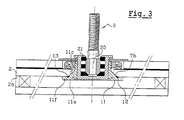
- Figure 3 shows, in cross section, a second form of realization of the device according to the invention, also applied to a double glazed panel.
- the main difference lies in the shape of the plate 11a of the ring. ring finger 11.
- the plate 11a present on its periphery, in this form of embodiment, a crown 11f coming to bear on the distal face 2b of the flank 2.
- This crown 11f thus reinforces the abutment effect obtained by the complementarity of the shapes of the surfaces 7b of the opening 7 of the sidewall 2 and 11c of the annular ring 11.
- the groove 12 provided on the annular ring 11 is at the junction of the surface 11c and the crown 11f.
- the butyl filling 13 can be arranged at the level of the connection of surfaces 7b and 2b of the distal flank 2.
- distal end 10 of the elongate fixing element 8 does not no longer has a substantially spherical shape such as a ball joint but is replaced by a substantially cylindrical part 20 linked to the body of holding 18 by semi-rigid elements 21 of substantially shape annular and known in themselves.
- Any other known embodiment of the elongate fastening element 8 is possible, including that having no degree of freedom.
Landscapes
- Engineering & Computer Science (AREA)
- Civil Engineering (AREA)
- Structural Engineering (AREA)
- Securing Of Glass Panes Or The Like (AREA)
- Load-Bearing And Curtain Walls (AREA)
- Joining Of Building Structures In Genera (AREA)
- Conveying And Assembling Of Building Elements In Situ (AREA)
Applications Claiming Priority (2)
| Application Number | Priority Date | Filing Date | Title |
|---|---|---|---|
| FR0000061 | 2000-01-04 | ||
| FR0000061A FR2803327B1 (fr) | 2000-01-04 | 2000-01-04 | Procede et dispositif de fixation pour panneaux a double flancs |
Publications (2)
| Publication Number | Publication Date |
|---|---|
| EP1114909A1 true EP1114909A1 (de) | 2001-07-11 |
| EP1114909B1 EP1114909B1 (de) | 2006-04-05 |
Family
ID=8845615
Family Applications (1)
| Application Number | Title | Priority Date | Filing Date |
|---|---|---|---|
| EP01400014A Expired - Lifetime EP1114909B1 (de) | 2000-01-04 | 2001-01-04 | Verfahren und Bausatz zur Befestigung von Tafeln mit doppelten Flanken |
Country Status (4)
| Country | Link |
|---|---|
| EP (1) | EP1114909B1 (de) |
| AT (1) | ATE322603T1 (de) |
| DE (1) | DE60118445T2 (de) |
| FR (1) | FR2803327B1 (de) |
Cited By (2)
| Publication number | Priority date | Publication date | Assignee | Title |
|---|---|---|---|---|
| EP2806092A1 (de) * | 2013-05-21 | 2014-11-26 | Jaakko Soini | Mehrscheiben-Isolierglaseinheit |
| US20220228425A1 (en) * | 2021-01-20 | 2022-07-21 | La Tecnica Nel Vetro S.P.A. | Structural, glass-aluminum facade component |
Citations (4)
| Publication number | Priority date | Publication date | Assignee | Title |
|---|---|---|---|---|
| EP0506522A1 (de) * | 1991-03-29 | 1992-09-30 | Saint-Gobain Vitrage | Befestigungssystem |
| EP0655543A1 (de) * | 1993-11-30 | 1995-05-31 | Saint-Gobain Vitrage | Mechanische Verbindung zwischen einer Glasscheibe und einer Tragestruktur |
| DE19512041C1 (de) * | 1995-03-31 | 1996-07-18 | Gebo Gmbh | Halterung für Platten an Gebäuden |
| EP0955437A2 (de) * | 1998-03-09 | 1999-11-10 | Laubeuf S.A. | Befestigungsvorrichtung und Verfahren mit einem Ring für Paneele |
-
2000
- 2000-01-04 FR FR0000061A patent/FR2803327B1/fr not_active Expired - Fee Related
-
2001
- 2001-01-04 AT AT01400014T patent/ATE322603T1/de not_active IP Right Cessation
- 2001-01-04 EP EP01400014A patent/EP1114909B1/de not_active Expired - Lifetime
- 2001-01-04 DE DE60118445T patent/DE60118445T2/de not_active Expired - Fee Related
Patent Citations (4)
| Publication number | Priority date | Publication date | Assignee | Title |
|---|---|---|---|---|
| EP0506522A1 (de) * | 1991-03-29 | 1992-09-30 | Saint-Gobain Vitrage | Befestigungssystem |
| EP0655543A1 (de) * | 1993-11-30 | 1995-05-31 | Saint-Gobain Vitrage | Mechanische Verbindung zwischen einer Glasscheibe und einer Tragestruktur |
| DE19512041C1 (de) * | 1995-03-31 | 1996-07-18 | Gebo Gmbh | Halterung für Platten an Gebäuden |
| EP0955437A2 (de) * | 1998-03-09 | 1999-11-10 | Laubeuf S.A. | Befestigungsvorrichtung und Verfahren mit einem Ring für Paneele |
Cited By (3)
| Publication number | Priority date | Publication date | Assignee | Title |
|---|---|---|---|---|
| EP2806092A1 (de) * | 2013-05-21 | 2014-11-26 | Jaakko Soini | Mehrscheiben-Isolierglaseinheit |
| US20220228425A1 (en) * | 2021-01-20 | 2022-07-21 | La Tecnica Nel Vetro S.P.A. | Structural, glass-aluminum facade component |
| US12534952B2 (en) * | 2021-01-20 | 2026-01-27 | La Tecnica Nel Vetro S.P.A. | Structural, glass-aluminum facade component |
Also Published As
| Publication number | Publication date |
|---|---|
| DE60118445T2 (de) | 2007-04-12 |
| FR2803327A1 (fr) | 2001-07-06 |
| FR2803327B1 (fr) | 2002-04-05 |
| ATE322603T1 (de) | 2006-04-15 |
| EP1114909B1 (de) | 2006-04-05 |
| DE60118445D1 (de) | 2006-05-18 |
Similar Documents
| Publication | Publication Date | Title |
|---|---|---|
| EP0506522B1 (de) | Befestigungssystem | |
| FR2830236A1 (fr) | Dispositif de fixation d'un pare-brise d'aeronef | |
| EP1950392A1 (de) | Vorrichtung zum Zusammenbau von zwei Einheiten, beispielsweise für den Stator eines Turbotriebwerks | |
| FR3095988A1 (fr) | Vitrage a porte-vitre en deux parties et procede de fabrication dudit vitrage | |
| EP1544481B1 (de) | Blechteil, das Mittel für Befestigung an einem Tragteil und einer Dichtung enthält | |
| FR2743040A1 (fr) | Mecanisme d'essuie-glace comportant des moyens perfectionnes de guidage et d'etancheite pour la traversee d'une tole par un arbre d'entrainement | |
| EP0458700A1 (de) | Abgedichtete Verbindung zweier stumpf aneinanderstossender glatter Rohre | |
| EP0402198A1 (de) | Verriegelungsmutter | |
| FR2920015A3 (fr) | Structure de vehicule automobile et procede de fixation d'un accessoire | |
| EP0788950B1 (de) | Kraftfahrzeug-Scheibenwischervorrichtung mit Scheibenwischer-Indexierungsmittelnunter Berücksichtigung der Antriebswelle | |
| EP1114909B1 (de) | Verfahren und Bausatz zur Befestigung von Tafeln mit doppelten Flanken | |
| EP1870602B1 (de) | Montageteil zur Verbindung von zwei Elementen miteinander, entsprechende Montagevorrichtung und Anwendung im Automobilbereich | |
| FR2891889A1 (fr) | Embout de connexion etanche et piece terminale pour un tel embout | |
| FR2774340A1 (fr) | Mecanisme d'essuie-glace de vehicule automobile | |
| EP0955437B1 (de) | Befestigungsvorrichtung und Verfahren mit einem Ring für Paneele | |
| EP2841774B1 (de) | Element zur befestigung eines zubehörteils an einer halterung und der halterung an einer struktur | |
| EP0435748A1 (de) | Verbindungselement zwischen zwei Profilen | |
| EP0686751B1 (de) | Verbesserung an Mitteln für Befestigung und Halterung von in die Verglasung integrierte Struktur | |
| FR2607201A1 (fr) | Dispositif de fixation sur fut filete ou annele | |
| BE1012055A3 (fr) | Dispositif de fixation par ecrou. | |
| FR2748128A1 (fr) | Dispositif de fixation destine a realiser une liaison rigide entre un verre optique et un element de monture de lunettes | |
| EP1298019B1 (de) | Scheibenwischer-Antriebsmechanismus-Befestigungsanlage | |
| EP3802241B1 (de) | Scheibenwischvorrichtung mit einer steuerung zum betätigen einer öffnungsplatte | |
| EP3486505B1 (de) | Befestigungsverfahren von mindestens zwei teilen untereinander mithilfe einer befestigungseinheit, und entsprechende befestigungseinheit | |
| FR2886614A1 (fr) | Joint peripherique d'un vitrage d'optique d'un vehicule automobile |
Legal Events
| Date | Code | Title | Description |
|---|---|---|---|
| PUAI | Public reference made under article 153(3) epc to a published international application that has entered the european phase |
Free format text: ORIGINAL CODE: 0009012 |
|
| AK | Designated contracting states |
Kind code of ref document: A1 Designated state(s): AT BE CH CY DE DK ES FI FR GB GR IE IT LI LU MC NL PT SE TR |
|
| AX | Request for extension of the european patent |
Free format text: AL;LT;LV;MK;RO;SI |
|
| 17P | Request for examination filed |
Effective date: 20020107 |
|
| AKX | Designation fees paid |
Free format text: AT BE CH CY DE DK ES FI FR GB GR IE IT LI LU MC NL PT SE TR |
|
| 17Q | First examination report despatched |
Effective date: 20040929 |
|
| GRAP | Despatch of communication of intention to grant a patent |
Free format text: ORIGINAL CODE: EPIDOSNIGR1 |
|
| RTI1 | Title (correction) |
Free format text: METHOD AND KIT FOR FIXING PANELS WITH DOUBLE FLANKS |
|
| GRAS | Grant fee paid |
Free format text: ORIGINAL CODE: EPIDOSNIGR3 |
|
| GRAA | (expected) grant |
Free format text: ORIGINAL CODE: 0009210 |
|
| AK | Designated contracting states |
Kind code of ref document: B1 Designated state(s): AT BE CH CY DE DK ES FI FR GB GR IE IT LI LU MC NL PT SE TR |
|
| PG25 | Lapsed in a contracting state [announced via postgrant information from national office to epo] |
Ref country code: FI Free format text: LAPSE BECAUSE OF FAILURE TO SUBMIT A TRANSLATION OF THE DESCRIPTION OR TO PAY THE FEE WITHIN THE PRESCRIBED TIME-LIMIT Effective date: 20060405 Ref country code: NL Free format text: LAPSE BECAUSE OF FAILURE TO SUBMIT A TRANSLATION OF THE DESCRIPTION OR TO PAY THE FEE WITHIN THE PRESCRIBED TIME-LIMIT Effective date: 20060405 Ref country code: IT Free format text: LAPSE BECAUSE OF FAILURE TO SUBMIT A TRANSLATION OF THE DESCRIPTION OR TO PAY THE FEE WITHIN THE PRE;WARNING: LAPSES OF ITALIAN PATENTS WITH EFFECTIVE DATE BEFORE 2007 MAY HAVE OCCURRED AT ANY TIME BEFORE 2007. THE CORRECT EFFECTIVE DATE MAY BE DIFFERENT FROM THE ONE RECORDED.SCRIBED TIME-LIMIT Effective date: 20060405 |
|
| REG | Reference to a national code |
Ref country code: GB Ref legal event code: FG4D Free format text: NOT ENGLISH |
|
| REG | Reference to a national code |
Ref country code: CH Ref legal event code: EP |
|
| REG | Reference to a national code |
Ref country code: IE Ref legal event code: FG4D Free format text: LANGUAGE OF EP DOCUMENT: FRENCH |
|
| REF | Corresponds to: |
Ref document number: 60118445 Country of ref document: DE Date of ref document: 20060518 Kind code of ref document: P |
|
| PG25 | Lapsed in a contracting state [announced via postgrant information from national office to epo] |
Ref country code: DK Free format text: LAPSE BECAUSE OF FAILURE TO SUBMIT A TRANSLATION OF THE DESCRIPTION OR TO PAY THE FEE WITHIN THE PRESCRIBED TIME-LIMIT Effective date: 20060705 Ref country code: SE Free format text: LAPSE BECAUSE OF FAILURE TO SUBMIT A TRANSLATION OF THE DESCRIPTION OR TO PAY THE FEE WITHIN THE PRESCRIBED TIME-LIMIT Effective date: 20060705 |
|
| PG25 | Lapsed in a contracting state [announced via postgrant information from national office to epo] |
Ref country code: ES Free format text: LAPSE BECAUSE OF FAILURE TO SUBMIT A TRANSLATION OF THE DESCRIPTION OR TO PAY THE FEE WITHIN THE PRESCRIBED TIME-LIMIT Effective date: 20060716 |
|
| GBT | Gb: translation of ep patent filed (gb section 77(6)(a)/1977) |
Effective date: 20060719 |
|
| REG | Reference to a national code |
Ref country code: CH Ref legal event code: NV Representative=s name: GLN GRESSET & LAESSER NEUCHATEL CABINET DE CONSEIL |
|
| PG25 | Lapsed in a contracting state [announced via postgrant information from national office to epo] |
Ref country code: PT Free format text: LAPSE BECAUSE OF FAILURE TO SUBMIT A TRANSLATION OF THE DESCRIPTION OR TO PAY THE FEE WITHIN THE PRESCRIBED TIME-LIMIT Effective date: 20060905 |
|
| NLV1 | Nl: lapsed or annulled due to failure to fulfill the requirements of art. 29p and 29m of the patents act | ||
| PG25 | Lapsed in a contracting state [announced via postgrant information from national office to epo] |
Ref country code: IE Free format text: LAPSE BECAUSE OF NON-PAYMENT OF DUE FEES Effective date: 20070104 |
|
| PG25 | Lapsed in a contracting state [announced via postgrant information from national office to epo] |
Ref country code: CH Free format text: LAPSE BECAUSE OF NON-PAYMENT OF DUE FEES Effective date: 20070131 Ref country code: MC Free format text: LAPSE BECAUSE OF NON-PAYMENT OF DUE FEES Effective date: 20070131 Ref country code: LI Free format text: LAPSE BECAUSE OF NON-PAYMENT OF DUE FEES Effective date: 20070131 |
|
| PLBE | No opposition filed within time limit |
Free format text: ORIGINAL CODE: 0009261 |
|
| STAA | Information on the status of an ep patent application or granted ep patent |
Free format text: STATUS: NO OPPOSITION FILED WITHIN TIME LIMIT |
|
| 26N | No opposition filed |
Effective date: 20070108 |
|
| PG25 | Lapsed in a contracting state [announced via postgrant information from national office to epo] |
Ref country code: DE Free format text: LAPSE BECAUSE OF NON-PAYMENT OF DUE FEES Effective date: 20070801 |
|
| REG | Reference to a national code |
Ref country code: CH Ref legal event code: PL |
|
| GBPC | Gb: european patent ceased through non-payment of renewal fee |
Effective date: 20070104 |
|
| PG25 | Lapsed in a contracting state [announced via postgrant information from national office to epo] |
Ref country code: GB Free format text: LAPSE BECAUSE OF NON-PAYMENT OF DUE FEES Effective date: 20070104 |
|
| PG25 | Lapsed in a contracting state [announced via postgrant information from national office to epo] |
Ref country code: GR Free format text: LAPSE BECAUSE OF FAILURE TO SUBMIT A TRANSLATION OF THE DESCRIPTION OR TO PAY THE FEE WITHIN THE PRESCRIBED TIME-LIMIT Effective date: 20060706 |
|
| PGFP | Annual fee paid to national office [announced via postgrant information from national office to epo] |
Ref country code: LU Payment date: 20080204 Year of fee payment: 8 |
|
| PG25 | Lapsed in a contracting state [announced via postgrant information from national office to epo] |
Ref country code: AT Free format text: LAPSE BECAUSE OF NON-PAYMENT OF DUE FEES Effective date: 20070104 |
|
| PGFP | Annual fee paid to national office [announced via postgrant information from national office to epo] |
Ref country code: BE Payment date: 20080131 Year of fee payment: 8 |
|
| PG25 | Lapsed in a contracting state [announced via postgrant information from national office to epo] |
Ref country code: CY Free format text: LAPSE BECAUSE OF FAILURE TO SUBMIT A TRANSLATION OF THE DESCRIPTION OR TO PAY THE FEE WITHIN THE PRESCRIBED TIME-LIMIT Effective date: 20060405 |
|
| PG25 | Lapsed in a contracting state [announced via postgrant information from national office to epo] |
Ref country code: TR Free format text: LAPSE BECAUSE OF FAILURE TO SUBMIT A TRANSLATION OF THE DESCRIPTION OR TO PAY THE FEE WITHIN THE PRESCRIBED TIME-LIMIT Effective date: 20060405 |
|
| PG25 | Lapsed in a contracting state [announced via postgrant information from national office to epo] |
Ref country code: BE Free format text: LAPSE BECAUSE OF NON-PAYMENT OF DUE FEES Effective date: 20090131 |
|
| PG25 | Lapsed in a contracting state [announced via postgrant information from national office to epo] |
Ref country code: LU Free format text: LAPSE BECAUSE OF NON-PAYMENT OF DUE FEES Effective date: 20090104 |
|
| PGFP | Annual fee paid to national office [announced via postgrant information from national office to epo] |
Ref country code: FR Payment date: 20140129 Year of fee payment: 14 |
|
| REG | Reference to a national code |
Ref country code: FR Ref legal event code: ST Effective date: 20150930 |
|
| PG25 | Lapsed in a contracting state [announced via postgrant information from national office to epo] |
Ref country code: FR Free format text: LAPSE BECAUSE OF NON-PAYMENT OF DUE FEES Effective date: 20150202 |