EP1114977B1 - Zündeinrichtung, insbesondere für eine Mörsergranate - Google Patents
Zündeinrichtung, insbesondere für eine Mörsergranate Download PDFInfo
- Publication number
- EP1114977B1 EP1114977B1 EP01100229A EP01100229A EP1114977B1 EP 1114977 B1 EP1114977 B1 EP 1114977B1 EP 01100229 A EP01100229 A EP 01100229A EP 01100229 A EP01100229 A EP 01100229A EP 1114977 B1 EP1114977 B1 EP 1114977B1
- Authority
- EP
- European Patent Office
- Prior art keywords
- arming
- safety
- spring
- safe position
- firing device
- Prior art date
- Legal status (The legal status is an assumption and is not a legal conclusion. Google has not performed a legal analysis and makes no representation as to the accuracy of the status listed.)
- Expired - Lifetime
Links
Images


Classifications
-
- F—MECHANICAL ENGINEERING; LIGHTING; HEATING; WEAPONS; BLASTING
- F42—AMMUNITION; BLASTING
- F42C—AMMUNITION FUZES; ARMING OR SAFETY MEANS THEREFOR
- F42C1/00—Impact fuzes, i.e. fuzes actuated only by ammunition impact
- F42C1/02—Impact fuzes, i.e. fuzes actuated only by ammunition impact with firing-pin structurally combined with fuze
- F42C1/04—Impact fuzes, i.e. fuzes actuated only by ammunition impact with firing-pin structurally combined with fuze operating by inertia of members on impact
-
- F—MECHANICAL ENGINEERING; LIGHTING; HEATING; WEAPONS; BLASTING
- F42—AMMUNITION; BLASTING
- F42C—AMMUNITION FUZES; ARMING OR SAFETY MEANS THEREFOR
- F42C15/00—Arming-means in fuzes; Safety means for preventing premature detonation of fuzes or charges
- F42C15/28—Arming-means in fuzes; Safety means for preventing premature detonation of fuzes or charges operated by flow of fluent material, e.g. shot, fluids
- F42C15/295—Arming-means in fuzes; Safety means for preventing premature detonation of fuzes or charges operated by flow of fluent material, e.g. shot, fluids operated by a turbine or a propeller; Mounting means therefor
Definitions
- the invention relates to an ignition device for a mortar shell, which is adjustable by means of a spring device from a securing in a focus, according to the preamble of claim 1.
- the invention is based on DE 31 26 288 A. This describes an ignition device for a mortar shell with a fuse unit with a first and a second Entommesbolzen and a wind turbine, wherein between a connected to the wind turbine wind turbine shaft and the second Entommesbolzen a locking plate is provided.
- US Pat. No. 3,842,743 A describes an ignition device which can be adjusted by means of a spring device from securing into an in-focus position.
- the ignition device has a wind turbine, which is provided for biasing the spring device in order to adjust the ignition of the securing in the armed position.
- the object of the invention is to provide an ignition device which ensures both the safety properties in ensuring the ignition device and the Enttechnischskriterien.
- the ignition device according to the invention has the advantage that in its assurance in the spring device no or only a very small mechanical energy is stored, so that the safety properties are optimal.
- the necessary for adjusting the ignition of the assurance in the sheep position mechanical tension of the spring means takes place only after leaving the Weapon tube from which the mortar shell is fired, with the help of the provided on the mortar shell wind turbine by a suitable operative connection of the wind turbine with the spring means, which may be formed as a helical torsion spring.
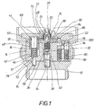
- FIG. 1 shows a rear end section of a mortar shell 10, which has an ignition device 14 with a safety device (SE) housing in a receiving space 12 provided for this purpose.
- SE housing 16 is combined with a board 18 having a central sleeve 20.
- the central sleeve 20 of the board 18 and the receiving space 12 occlusive cover 22 are used to support a wind turbine shaft 24 which is connected to a (not shown) wind turbine of the mortar shell 10.
- the wind turbine shaft 24 is formed at its end remote from the wind turbine end portion with a wedge-shaped slot 26 into which in the securing of the ignition device 14 a wedge-shaped slot 26 corresponding wedge-shaped coupling portion 28 of a screw 30 positively rests.
- the worm 30 is mounted with a bearing pin 32 remote from the wedge-shaped coupling portion 28 in a blind hole of a driver 34.
- the driver 34 is formed with a radially projecting nose 36 mounted in a sleeve 38 which is formed with a slot 40.
- the nose 36 of the driver 34 is in the focus of the ignition device 14 in the slot 40 in the sleeve 38th
- a toothed sleeve 44 of a Entsperrstriebes is rotatably mounted in a storage space 42 of the SE housing 16.
- the toothed sleeve 44 has an internally threaded portion 46 and two external sprockets 48 and 50.
- a threaded portion 52 of a Entommeswelle 54 is screwed in the internally threaded portion 46.
- the Entommeswelle 54 extends against rotation secured by a through hole 56 in the SE housing 16 in the assurance in a blind hole 58 into it.
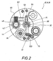
- the worm 30 is operatively connected to the outer ring gear 48 of the toothed sleeve 44 of the armature drive by means of a connecting device 60, which has a worm gear 64 meshing with the worm 30 at one end section of a connecting shaft 62 another remote end section thereof has a worm 66 meshing with the outer ring gear 48 of the toothed sleeve 44.
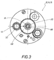
- the output gear 68 is formed, for example, with an arcuate slot 70 which is concentric with the wind turbine shaft 24 and which may have an arcuate opening angle of approximately 30 degrees of angle.
- a first release bolt 76 and a second release bolt 78 are mounted axially movable.
- the first Entracsbolzen 76 is forced by means of an associated helical compression spring 80 and the second Entommesbolzen 78 is by means of an associated helical compression spring 82 against the board 18.
- the second Enttechnischsbolzen 78 extends through a locking plate 84 between the SE housing 16 and the board 18 and through the board 18 in a blind hole 86 into which is formed in the lid 22.
- the worm 30 is formed with a chamfer surface 88 on which the locking plate 84 in the securing of the ignition device 14 is positively applied to prevent rotation of the spindle 30.
- the SE housing 16 rotates into the armed position shown in Figure 5, wherein the impact weight 92 by the safety lever 98 (see Figure 4) is unlocked.
- the not-depicted wind turbine i. the wind turbine shaft 24 about 600 revolutions during which the spring means 74 is mechanically tensioned.
- the SE housing is in the unlocked position, i. If he takes the focus, the worm 30 and the driver 34 is axially displaced and thus decoupled.
- the decoupled state shown in Figure 5 the positive connection between the wedge-shaped slot 26 of the wind turbine shaft 24 and the wedge-shaped coupling portion 28 of the screw 30 is released, so that the wind turbine shaft 24 can rotate freely.
- the operative connection between the SE housing 16 and the spring device 74 is canceled in the armed position. In the armed position, the driver 34 locks the SE housing 16.
- the formed in the output gear 68 arcuate slot 70 serves to improve it to ensure startup behavior of the wind turbine shaft 24, because the spring means 74 is only mechanically tensioned after the output gear 68 has rotated, for example, by about 30 degrees.
Landscapes
- Engineering & Computer Science (AREA)
- General Engineering & Computer Science (AREA)
- Fuses (AREA)
- Automotive Seat Belt Assembly (AREA)
- Wind Motors (AREA)
- Led Device Packages (AREA)
- Feeding, Discharge, Calcimining, Fusing, And Gas-Generation Devices (AREA)
- Air Bags (AREA)
- Catching Or Destruction (AREA)
Description
- Die Erfindung betrifft eine Zündeinrichtung für eine Mörsergranate, welche mittels einer Federeinrichtung von einer Sicherstellung in eine Scharfstellung verstellbar ist, gemäß dem Oberbegriff des Anspruchs 1.
- Die Erfindung geht von der DE 31 26 288 A aus. Diese beschreibt eine Zündeinrichtung für eine Mörsergranate mit einer Sicherungs-Einheit mit einem ersten und einem zweiten Entsicherungsbolzen und einem Windrad, wobei zwischen einer mit dem Windrad verbundenen Windradwelle und dem zweiten Entsicherungsbolzen ein Sicherungsblech vorgesehen ist.
- Des Weiteren beschreibt die US 3 842 743 A eine Zündeinrichtung, welche mittels einer Federeinrichtung von einer Sicherstellung in eine Scharfstellung verstellbar ist. Die Zündeinrichtung weist ein Windrad auf, das zum Vorspannen der Federeinrichtung vorgesehen ist, um die Zündeinrichtung von der Sicherstellung in die Scharfstellung zu verstellen.
- Aufgabe der Erfindung ist es, eine Zündeinrichtung zu schaffen, die sowohl die Sicherheitseigenschaften in der Sicherstellung der Zündeinrichtung als auch die Entsicherungskriterien gewährleistet.
- Diese Aufgabe wird erfindungsgemäß durch die kennzeichnenden Merkmale des Anspruches 1 erreicht.
- Vorteilhafte Weiterbildungen der Erfindung sind in den Unteransprüchen angegeben.
- Die erfindungsgemäße Zündeinrichtung weist den Vorteil auf, dass in ihrer Sicherstellung in der Federeinrichtung keine oder nur eine sehr kleine mechanische Energie gespeichert ist, so dass die Sicherheitseigenschaften optimal sind. Die zum Verstellen der Zündeinrichtung von der Sicherstellung in die Schafstellung notwendige mechanische Spannung der Federeinrichtung erfolgt erst nach Verlassen des Waffenrohres, aus welchem die Mörsergranate abgefeuert wird, mit Hilfe des an der Mörsergranate vorgesehen Windrades durch eine geeignete Wirkverbindung des Windrades mit der Federeinrichtung, die als schraubenförmige Drehfeder ausgebildet sein kann.
- Weitere Einzelheiten, Merkmale und Vorteile ergeben sich aus der nachfolgenden Beschreibung eines in der Zeichnung dargestellten Ausführungsbeispieles der erfindungsgemäßen Zündeinrichtung für eine abgeschnitten gezeichnete Mörsergranate. Es zeigen:
- Figur 1
- einen Längsschnitt durch die Zündeinrichtung,
- Figur 2
- einen Querschnitt durch die Zündeinrichtung,
- Figur 3
- einen anderen Querschnitt durch die Zündeinrichtung, d. h. einen Querschnitt entlang einer anderen Schnittebene,
- Figur 4
- einen der Figur 1 ähnlichen Längsschnitt zur Verdeutlichung der Sicherstellung der Zündeinrichtung, und
- Figur 5
- eine der Figur 4 ähnliche Längsschnittdarstellung zur Verdeutlichung der Scharfstellung der Zündeinrichtung.
- Figur 1 zeigt einen rückseitigen Endabschnitt einer Mörsergranate 10, die in einem dafür vorgesehenen Aufnahmeraum 12 eine Zündeinrichtung 14 mit einem Sicherungseinrichtung (SE)-Gehäuse aufweist. Das SE-Gehäuse 16 ist mit einer Platine 18 kombiniert, die eine zentrale Hülse 20 aufweist. Die zentrale Hülse 20 der Platine 18 und ein den Aufnahmeraum 12 verschließender Deckel 22 dienen zur Lagerung einer Windradwelle 24, die mit einem (nicht gezeichneten) Windrad der Mörsergranate 10 verbunden ist. Die Windradwelle 24 ist an ihrem vom Windrad entfernten Endabschnitt mit einem keilförmigen Schlitz 26 ausgebildet, in den in der Sicherstellung der Zündeinrichtung 14 ein dem keilförmigen Schlitz 26 entsprechender keilförmiger Kupplungsabschnitt 28 einer Schnecke 30 formschlüssig hineinsteht. Die Schnecke 30 ist mit einem vom keilförmigen Kupplungsabschnitt 28 abgewandten Lagerzapfen 32 in einem Sackloch eines Mitnehmers 34 gelagert. Der Mitnehmer 34 ist mit einer radial wegstehenden Nase 36 ausgebildet in einer Hülse 38 gelagert, die mit einem Schlitz 40 ausgebildet ist. Die Nase 36 des Mitnehmers 34 befindet sich in der Scharfstellung der Zündeinrichtung 14 im Schlitz 40 in der Hülse 38.
- In einem Lagerraum 42 des SE-Gehäuses 16 ist eine Zahnhülse 44 eines ein Entsicherungstriebes drehbar gelagert. Die Zahnhülse 44 weist einen Innengewindeabschnitt 46 und zwei Außenzahnkränze 48 und 50 auf. In den Innengewindeabschnitt 46 ist ein Gewindeabschnitt 52 einer Entsicherungswelle 54 eingeschraubt. Die Entsicherungswelle 54 erstreckt sich gegen Verdrehung gesichert durch ein Durchgangsloch 56 im SE-Gehäuse 16 in der Sicherstellung in ein Sackloch 58 hinein.
- Wie aus Figur 2 ersichtlich ist, ist die Schnecke 30 mit dem Außenzahnkranz 48 der Zahnhülse 44 des Entsicherungstriebes mittels einer Verbindungseinrichtung 60 drehmomentübertragend wirkverbunden, die am einen Endabschnitt einer Verbindungswelle 62 ein mit der Schnecke 30 kämmendes Schneckenrad 64 und am davon entfernten anderen Endabschnitt eine mit dem Außenzahnkranz 48 der Zahnhülse 44 kämmende Schnecke 66 aufweist.
- Mit dem zweiten Außenzahnkranz 50 der Zahnhülse 44 des Entsicherungstriebes ist ein Abtriebsrad 68 kämmend in Eingriff, das an der zentralen Hülse 20 der Platine 18 gelagert ist. Das Abtriebsrad 68 ist beispielsweise mit einem zur Windradwelle 24 konzentrischen bogenförmigen Langloch 70 ausgebildet, das einen bogenförmigen Öffnungswinkel von ca. 30 Winkelgrad besitzen kann. In das bogenförmige Langloch 70 steht ein Endabschnitt 72 einer Federeinrichtung 74 hinein, die als schraubenförmige Drehfeder ausgebildet ist. Der zweite Endabschnitt der Federeinrichtung 74 ist an der zentralen Hülse 20 fixiert.
- Im SE-Gehäuse 16 sind ein erster Entsicherungsbolzen 76 und ein zweiter Entsicherungsbolzen 78 axial beweglich gelagert. Der erste Entsicherungsbolzen 76 ist mit Hilfe einer zugehörigen Schraubendruckfeder 80 und der zweiten Entsicherungsbolzen 78 ist mit Hilfe einer zugehörigen Schraubendruckfeder 82 gegen die Platine 18 gezwängt. Der zweite Entsicherungsbolzen 78 erstreckt sich durch ein Sicherungsblech 84 zwischen dem SE-Gehäuse 16 und der Platine 18 und durch die Platine 18 in ein Sackloch 86 hinein, das im Deckel 22 ausgebildet ist.
- Die Schnecke 30 ist mit einer Fasenfläche 88 ausgebildet, an der das Sicherungsblech 84 in der Sicherstellung der Zündeinrichtung 14 formschlüssig anliegt, um eine Drehung der Spindel 30 zu verhindern.
- Die Wirkungsweise der Zündeinrichtung 14 ist wie folgt:
- 1. Sicherstellung:
In der Sicherstellung befinden sich der erste und der zweite Entsicherungsbolzen 76 und 78 und die Entsicherungswelle 54 in der in Figur 1 gezeichneten Stellung. Die Federeinrichtung 74 befindet sich in einem nicht gespannten Zustand, d.h. in der Federeinrichtung 74 ist keine Energie gespeichert. Das Sicherungsblech 86 sperrt mit Hilfe des zweiten Entsicherungsbolzens 78 die Windradwelle 24.
Wie aus Figur 4 ersichtlich ist, ist im SE-Gehäuse 16 in einem dafür vorgesehenen Aufnahmeraum 90 ein Aufschlaggewicht 92 mit einen Detonator angeordnet.
An der Platine 18 ist eine dem Detonator 94 zugeordnete Zündnadel 96 vorgesehen.
In der Sicherstellung wird das Aufschlaggewicht 92 mittels eines federnden Sicherungshebels 98 (sh. Figur 4), d.h. mittels eines Sicherungshebels 98 und einer nicht gezeichneten Sicherungsfeder im Aufnahmeraum 90 des SE-Gehäuses 16 von der Zündnadel 96 beabstandet festgehalten. - 2. Scharfstellung:
Beim Abschuß der Mörsergranate 10 aus einem Waffenrohr wird zuerst der erste Entsicherungsbolzen 76 trägheitsbedingt gegen die zugehörige Schraubendruckfeder 80 bewegt, so daß sich die zwischen dem ersten und dem zweiten Entsicherungsbolzen 76 und 78 befindliche Kugel 100 in Figur 1 nach rechts bewegen kann. Hierdurch wird der zweite Entsicherungsbolzen 78 freigegeben, d.h. er kann sich im Anschluß an den ersten Entsicherungsbolzen 76 trägheitsbedingt gegen seine zugehörige Schraubendruckfeder 82 bewegen. Dabei bewegt sich der zweite Entsicherungsbolzen 78 aus dem Sackloch 86 im Deckel 22 und aus der Platine 18 und aus dem Sicherungsblech 84 heraus und gibt das Sicherungsblech 84 frei. Das bedeutet, daß die Windradwelle 24 nicht länger an einer Drehung gehindert, sondern freigegeben wird. Die Windradwelle 24 kann sich also drehen und spannt die Federeinrichtung 74. Bei dieser Drehung der Windradwelle 24 wird gleichzeitig die Entsicherungswelle 54 aus dem Sackloch 58 herausbewegt, so daß das SE-Gehäuse 16 im Aufnahmeraum 12 nicht länger gegen eine Drehung gesichert sondern freigegeben wird. Auf diese Weise ergibt sich eine Vorrohrsicherheit. - Das SE-Gehäuse 16 dreht sich in die auch in Figur 5 gezeichnete Scharfstellung, wobei das Aufschlaggewicht 92 durch den Sicherungshebel 98 (sh. Figur 4) entsichert wird.
- Beispielsweise führt das nicht gezeichnete Windrad, d.h. die Windradwelle 24 ca. 600 Umdrehungen aus, während welchen die Federeinrichtung 74 mechanisch gespannt wird. Befindet sich das SE-Gehäuse in der entsicherten Stellung, d.h. nimmt er die Scharfstellung ein, so wird die Schnecke 30 und der Mitnehmer 34 axial verstellt und somit ausgekoppelt. Im in Figur 5 gezeichneten ausgekoppelten Zustand ist die formschlüssige Verbindung zwischen dem keilförmigen Schlitz 26 der Windradwelle 24 und dem keilförmigen Kupplungsabschnitt 28 der Schnecke 30 aufgehoben, so daß sich die Windradwelle 24 frei drehen kann. Die Wirkverbindung zwischen dem SE-Gehäuse 16 und der Federeinrichtung 74 ist in der Scharfstellung aufgehoben. In der Scharfstellung arretiert der Mitnehmer 34 das SE-Gehäuse 16.
- Das im Abtriebsrad 68 ausgebildete bogenförmige Langloch 70 dient dazu, ein verbessert es Anlaufverhalten der Windradwelle 24 zu gewährleisten, weil die Federeinrichtung 74 erst mechanisch gespannt wird, nachdem sich das Abtriebsrad 68 beispielsweise um ca. 30 Winkelgrad gedreht hat.
- Eine andere Möglichkeit besteht beispielsweise darin, die Federeinrichtung 74 beim Einbau in die Gegendrehrichtung entsprechend vorzuspannen. In diesem Falle kann der Endabschnitt 72 der Federeinrichtung 74 am Abtriebsrad 68 fixiert sein. Auch durch eine solche geringfügige mechanische Vorspannung in Gegendrehrichtung ist das Anlaufverhalten wunschgemäß zu verbessern; hierbei ist jedoch - wie bei bekannten Zündeinrichtungen - die Federeinrichtung - wenn auch relativ geringfügig - mechanisch vorgespannt.
Claims (5)
- Zündeinrichtung (14) für eine Mörsergranate (10), welche mittels einer Federeinrichtung (74) von einer Sicherstellung in eine Scharfstellung verstellbar ist, wobei die Zündeinrichtung (14) ein Windrad zur Entsicherung eines In Sicherstellung arretierten, einen Detonator (94) aufweisenden, verstellbaren Sicherungseinrichtung-Gehäuses (16) sowie
einen ersten und einen zweiten Entsicherungsbolzen (76, 78) aufweist,
wobei zwischen einer mit dem Windrad verbundenen Windradwelle und dem zweiten Entsicherungsbolzen ein Sicherungsblech vorgesehen ist,
dadurch gekennzeichnet,
dass die Windradwelle (24) in der Sicherstellung mit einer Schnecke (30) drehmomentübertragend gekoppelt ist, die mit einer Zahnhülse (44) eines Entsicherungstriebes wirkverbunden ist, mittels welchem das Sicherungseinrichtung-Gehäuse (16) durch die Entsicherungswelle (54) in eine Vorrohrsicherstellung freigebbar ist, und dass
der Entsicherungstrieb ein Abtriebsrad (68) aufweist, das zum Vorspannen der Federeinrichtung (74) vorgesehen ist,
um das Sicherungseinrichtung-Gehäuse (16) von der Sicherstellung in die Scharfstellung zu verstellen. - Zündeinrichtung nach Anspruch 1,
dadurch gekennzeichnet,
dass das Abtriebsrad (68) mit einem zur Windradwelle (24) konzentrischen bogenförmigen Langloch (70) ausgebildet ist, in welchem ein Endabschnitt (72) des Federelementes (74) vorgesehen ist. - Zündeinrichtung nach Anspruch 1,
dadurch gekennzeichnet,
dass die Federeinrichtung (74) mit einem Endabschnitt am Antriebsrad (68) festgelegt und in Gegendrehrichtung vorspannt ist. - Zündeinrichtung nach Anspruch 1,
dadurch gekennzeichnet,
dass im Sicherungseinrichtung-Gehäuse (16) ein Aufschlaggewicht (92) vorgesehen ist, das in der Sicherstellung mittels eines federnd gespannten Entsicherungshebels (98) von einer Zündnadel (96) beabstandet ist. - Zündeinrichtung nach Anspruch 1,
dadurch gekennzeichnet,
dass die Schnecke (30) mittels eines Mitnehmers (34) das Sicherungseinrichtung-Gehäuse (16) in der Scharfstellung arretiert.
Applications Claiming Priority (2)
| Application Number | Priority Date | Filing Date | Title |
|---|---|---|---|
| DE10000177A DE10000177A1 (de) | 2000-01-05 | 2000-01-05 | Zündeinrichtung, insbesondere für eine Mörsergranate |
| DE10000177 | 2000-01-05 |
Publications (2)
| Publication Number | Publication Date |
|---|---|
| EP1114977A1 EP1114977A1 (de) | 2001-07-11 |
| EP1114977B1 true EP1114977B1 (de) | 2006-05-10 |
Family
ID=7626773
Family Applications (1)
| Application Number | Title | Priority Date | Filing Date |
|---|---|---|---|
| EP01100229A Expired - Lifetime EP1114977B1 (de) | 2000-01-05 | 2001-01-03 | Zündeinrichtung, insbesondere für eine Mörsergranate |
Country Status (13)
| Country | Link |
|---|---|
| US (1) | US6463855B2 (de) |
| EP (1) | EP1114977B1 (de) |
| KR (1) | KR100675764B1 (de) |
| AT (1) | ATE326004T1 (de) |
| AU (1) | AU774459B2 (de) |
| CZ (1) | CZ293404B6 (de) |
| DE (2) | DE10000177A1 (de) |
| ES (1) | ES2262561T3 (de) |
| IL (1) | IL140663A (de) |
| PL (1) | PL196699B1 (de) |
| SG (1) | SG115350A1 (de) |
| SK (1) | SK285078B6 (de) |
| ZA (1) | ZA200100080B (de) |
Families Citing this family (10)
| Publication number | Priority date | Publication date | Assignee | Title |
|---|---|---|---|---|
| US6920826B2 (en) * | 2000-09-15 | 2005-07-26 | Junghans Feinwerktechnik Gmbh & Co. Kg | Energy supply device having a shaft rotatably supported on a polytetrafluroethylene bearing surface |
| US6883434B2 (en) * | 2001-09-17 | 2005-04-26 | Junghans Feinwerktechnik Gmbh & Co. Kg | Fuse device for a projectile |
| WO2003095933A1 (de) * | 2002-05-13 | 2003-11-20 | Ruag Munition | Aufschlagzünder |
| US6779457B2 (en) * | 2002-05-17 | 2004-08-24 | Ruag Munition | Percussion fuse (ignition device) |
| DE102006046811A1 (de) * | 2006-10-02 | 2008-04-03 | Junghans Microtec Gmbh | Geschosszünder |
| FR2959303B1 (fr) * | 2010-04-27 | 2012-04-06 | Nexter Munitions | Dispositif d'amorcage a initiation electrique pour projectile |
| DE102012001219B4 (de) | 2012-01-21 | 2014-07-31 | Junghans Microtec Gmbh | Geschosszünder, hierzu ausgebildetes Waffenrohr und Verfahren |
| KR101666217B1 (ko) | 2016-01-27 | 2016-10-24 | 주식회사 풍산에프앤에스 | 포탄용 신관의 시간차 관성 감응식 안전장전구조 |
| EP3647538A1 (de) * | 2018-10-30 | 2020-05-06 | Siemens Aktiengesellschaft | Sicherheitsvorrichtung zum eindämmen einer energiefreisetzung einer rotoren-anordnung |
| FR3127563B1 (fr) * | 2021-09-27 | 2023-08-25 | Dixi Microtechniques | Fuseé mécanique auto-percutante pour une munition non girante |
Family Cites Families (27)
| Publication number | Priority date | Publication date | Assignee | Title |
|---|---|---|---|---|
| FR340346A (fr) * | 1904-02-10 | 1904-07-02 | Carl Puff | Système de fusée pour obus, à deux ou plusieurs capsules fulminantes pour l'amorce au point de chute |
| US772470A (en) * | 1904-05-21 | 1904-10-18 | Bethlehem Steel Corp | Mechanical time-fuse for explosive projectiles. |
| GB190715796A (en) * | 1907-07-09 | 1908-06-11 | Frederick Richard Simms | Improvements in Flying Machines. |
| US3140661A (en) * | 1946-11-19 | 1964-07-14 | Allen S Clarke | Generator-powered fuze |
| NL236971A (de) * | 1958-03-28 | |||
| US3552318A (en) * | 1968-05-03 | 1971-01-05 | Us Navy | Ordnance fuze |
| US3677186A (en) * | 1969-10-01 | 1972-07-18 | Us Navy | Velocity discriminating time mechanical ordnance fuze |
| US3677185A (en) * | 1969-10-13 | 1972-07-18 | Us Navy | Arming device |
| CH531158A (fr) * | 1970-11-03 | 1972-11-30 | Mefina Sa | Dispositif de sécurité pour fusée de projectile à mouvement giratoire |
| NO130656C (de) * | 1973-01-10 | 1975-01-15 | Kongsberg Vapenfab As | |
| US3842743A (en) * | 1973-05-29 | 1974-10-22 | C Zittle | Air-driven turbine safe and arm arrangement for a free-falling ordnance device |
| DE2643828C3 (de) * | 1976-09-29 | 1980-09-11 | Gebrueder Junghans Gmbh, 7230 Schramberg | Zünder für drallarm zu verschießende Geschosse |
| US4419934A (en) * | 1980-08-28 | 1983-12-13 | Werkzeugmaschinenfabrik Oerlikon-Buhrle Ag | Safety apparatus for a spinning projectile fuse |
| DE3107110C2 (de) * | 1981-02-26 | 1984-03-29 | Gebrüder Junghans GmbH, 7230 Schramberg | Sicherungsvorrichtung für Zünder von Drallgeschossen |
| DE3108659C2 (de) * | 1981-03-07 | 1985-01-03 | Gebrüder Junghans GmbH, 7230 Schramberg | Sicherungsvorrichtung für Zünder von drallfreien bzw. drallarmen Geschossen |
| DE3126288A1 (de) * | 1981-07-03 | 1983-05-26 | Diehl GmbH & Co, 8500 Nürnberg | Sicherungseinrichtung fuer geschosszuender |
| DE3418759A1 (de) | 1984-05-19 | 1985-11-21 | Diehl GmbH & Co, 8500 Nürnberg | Zuendsicherungseinrichtung |
| DE3660940D1 (en) * | 1985-04-04 | 1988-11-17 | Oerlikon Buehrle Ag | Safety device for a fuze activated by the rotation of a projectile |
| EP0227919B1 (de) * | 1985-12-17 | 1989-05-03 | Werkzeugmaschinenfabrik Oerlikon-Bührle AG | Aufschlagzünder für ein Geschoss |
| DE3742575A1 (de) * | 1987-12-16 | 1989-07-06 | Junghans Gmbh Geb | Zuender |
| DE3935180A1 (de) * | 1989-10-23 | 1991-04-25 | Junghans Gmbh Geb | Sicherungseinrichtung eines geschosszuenders |
| US5016532A (en) * | 1989-11-03 | 1991-05-21 | Motorola, Inc. | Safe and arm device |
| DE4112960C2 (de) * | 1991-04-20 | 1994-05-11 | Junghans Gmbh Geb | Sicherungseinrichtung mit einem Rückschießbolzensystem für einen Rotor |
| US5269223A (en) * | 1992-10-06 | 1993-12-14 | Ems-Patvag | Piezoelectric fuse system with safe and arm device for ammunition |
| FR2726359B1 (fr) * | 1994-10-26 | 1996-11-29 | Thomson Brandt Armements | Fusee d'impact a double securite |
| DE9419261U1 (de) * | 1994-12-01 | 1996-04-04 | Gebrüder Junghans GmbH, 78713 Schramberg | Aufschlagzünder für Munition |
| US5714709A (en) * | 1995-04-20 | 1998-02-03 | Gebruder Junghans Gmbh | Apparatus for detonating a plurality of objects |
-
2000
- 2000-01-05 DE DE10000177A patent/DE10000177A1/de not_active Withdrawn
- 2000-12-04 AU AU72004/00A patent/AU774459B2/en not_active Ceased
- 2000-12-21 SK SK2000-2000A patent/SK285078B6/sk not_active IP Right Cessation
-
2001
- 2001-01-01 IL IL140663A patent/IL140663A/en not_active IP Right Cessation
- 2001-01-02 SG SG200100013A patent/SG115350A1/en unknown
- 2001-01-03 ES ES01100229T patent/ES2262561T3/es not_active Expired - Lifetime
- 2001-01-03 KR KR1020010000145A patent/KR100675764B1/ko not_active Expired - Fee Related
- 2001-01-03 AT AT01100229T patent/ATE326004T1/de not_active IP Right Cessation
- 2001-01-03 PL PL345014A patent/PL196699B1/pl unknown
- 2001-01-03 DE DE50109725T patent/DE50109725D1/de not_active Expired - Lifetime
- 2001-01-03 CZ CZ200125A patent/CZ293404B6/cs not_active IP Right Cessation
- 2001-01-03 EP EP01100229A patent/EP1114977B1/de not_active Expired - Lifetime
- 2001-01-04 ZA ZA200100080A patent/ZA200100080B/xx unknown
- 2001-01-05 US US09/754,208 patent/US6463855B2/en not_active Expired - Lifetime
Also Published As
| Publication number | Publication date |
|---|---|
| DE50109725D1 (de) | 2006-06-14 |
| PL345014A1 (en) | 2001-07-16 |
| ES2262561T3 (es) | 2006-12-01 |
| SG115350A1 (en) | 2005-10-28 |
| IL140663A0 (en) | 2002-02-10 |
| SK285078B6 (sk) | 2006-06-01 |
| AU7200400A (en) | 2001-07-12 |
| US20010017090A1 (en) | 2001-08-30 |
| ATE326004T1 (de) | 2006-06-15 |
| IL140663A (en) | 2006-07-05 |
| KR100675764B1 (ko) | 2007-01-29 |
| US6463855B2 (en) | 2002-10-15 |
| CZ200125A3 (cs) | 2001-09-12 |
| PL196699B1 (pl) | 2008-01-31 |
| SK20002000A3 (sk) | 2001-11-06 |
| DE10000177A1 (de) | 2001-07-12 |
| EP1114977A1 (de) | 2001-07-11 |
| ZA200100080B (en) | 2001-07-19 |
| KR20010070393A (ko) | 2001-07-25 |
| AU774459B2 (en) | 2004-06-24 |
| CZ293404B6 (cs) | 2004-04-14 |
Similar Documents
| Publication | Publication Date | Title |
|---|---|---|
| EP1114977B1 (de) | Zündeinrichtung, insbesondere für eine Mörsergranate | |
| DE2643828A1 (de) | Zuender fuer drallarm zu verschiessende geschosse | |
| EP1281110A1 (de) | Betätigungsvorrichtung | |
| EP0593720B1 (de) | Vorrichtung zum setzen eines selbstbohrenden klemmbefestigers | |
| EP1826527B1 (de) | Mechanischer Raketenzünder | |
| DE3519517C2 (de) | Sicherungseinrichtung für einen Zünder | |
| EP3408477B1 (de) | Schwenkriegelschloss | |
| DE1953685B2 (de) | LenkschloB für Kraftfahrzeuge | |
| DE19906268C2 (de) | Vorrichtung zur elektrischen Verriegelung der Lenkspindel einer Lenkeinrichtung | |
| EP2396145A1 (de) | Steckschlüssel zur montage eines laserzündsystems | |
| DE1578479B1 (de) | Geschosszuender | |
| EP0197359B1 (de) | Sicherungsvorrichtung für einen Drallgeschosszünder | |
| DE19617125A1 (de) | Anlasser mit verbesserter Ritzelsperreinrichtung | |
| DE102004060907B4 (de) | Verriegelungsvorrichtung zur Verriegelung einer automatisierten Feststellbremse eines Fahrzeugs | |
| DE2334104C2 (de) | Feuerwaffe mit einer elektrischen Abfeuerungsvorrichtung | |
| CH717174A2 (de) | Schliessvorrichtung für ein Gewehr. | |
| CH691557A5 (de) | Sicherungseinrichtung eines Geschosszünders. | |
| DE3242107C2 (de) | Zünder für drallarme und drallfreie Geschosse | |
| DE102024003024B3 (de) | Vorrichtung zur Begrenzung einer Lenkraddrehung | |
| DE1578483C3 (de) | Zeitsicherung eines Zeit- und Aufschlagzünders | |
| EP1553381B1 (de) | Zündeinrichtung | |
| DE29719524U1 (de) | Andrehvorrichtung für Brennkraftmaschinen | |
| DE2939711A1 (de) | Unterwasserzuender zum zuenden von sprengladungen | |
| DE4330577C2 (de) | Kampfmittelräumeinrichtung mit einem Zeitzündergerät und einer Zentraluhr | |
| DE1116477B (de) | Druckfederandrehmotor fuer Brennkraftmaschinen |
Legal Events
| Date | Code | Title | Description |
|---|---|---|---|
| PUAI | Public reference made under article 153(3) epc to a published international application that has entered the european phase |
Free format text: ORIGINAL CODE: 0009012 |
|
| AK | Designated contracting states |
Kind code of ref document: A1 Designated state(s): AT BE CH CY DE DK ES FI FR GB GR IE IT LI LU MC NL PT SE TR |
|
| AX | Request for extension of the european patent |
Free format text: AL;LT;LV;MK;RO;SI |
|
| 17P | Request for examination filed |
Effective date: 20010613 |
|
| AKX | Designation fees paid |
Free format text: AT BE CH CY DE DK ES FI FR GB GR IE IT LI LU MC NL PT SE TR |
|
| 17Q | First examination report despatched |
Effective date: 20041203 |
|
| GRAP | Despatch of communication of intention to grant a patent |
Free format text: ORIGINAL CODE: EPIDOSNIGR1 |
|
| GRAS | Grant fee paid |
Free format text: ORIGINAL CODE: EPIDOSNIGR3 |
|
| GRAA | (expected) grant |
Free format text: ORIGINAL CODE: 0009210 |
|
| AK | Designated contracting states |
Kind code of ref document: B1 Designated state(s): AT BE CH CY DE DK ES FI FR GB GR IE IT LI LU MC NL PT SE TR |
|
| PG25 | Lapsed in a contracting state [announced via postgrant information from national office to epo] |
Ref country code: IT Free format text: LAPSE BECAUSE OF FAILURE TO SUBMIT A TRANSLATION OF THE DESCRIPTION OR TO PAY THE FEE WITHIN THE PRESCRIBED TIME-LIMIT;WARNING: LAPSES OF ITALIAN PATENTS WITH EFFECTIVE DATE BEFORE 2007 MAY HAVE OCCURRED AT ANY TIME BEFORE 2007. THE CORRECT EFFECTIVE DATE MAY BE DIFFERENT FROM THE ONE RECORDED. Effective date: 20060510 Ref country code: IE Free format text: LAPSE BECAUSE OF FAILURE TO SUBMIT A TRANSLATION OF THE DESCRIPTION OR TO PAY THE FEE WITHIN THE PRESCRIBED TIME-LIMIT Effective date: 20060510 |
|
| REG | Reference to a national code |
Ref country code: GB Ref legal event code: FG4D Free format text: NOT ENGLISH |
|
| REG | Reference to a national code |
Ref country code: CH Ref legal event code: EP |
|
| REF | Corresponds to: |
Ref document number: 50109725 Country of ref document: DE Date of ref document: 20060614 Kind code of ref document: P |
|
| REG | Reference to a national code |
Ref country code: IE Ref legal event code: FG4D Free format text: LANGUAGE OF EP DOCUMENT: GERMAN |
|
| PG25 | Lapsed in a contracting state [announced via postgrant information from national office to epo] |
Ref country code: DK Free format text: LAPSE BECAUSE OF FAILURE TO SUBMIT A TRANSLATION OF THE DESCRIPTION OR TO PAY THE FEE WITHIN THE PRESCRIBED TIME-LIMIT Effective date: 20060810 |
|
| REG | Reference to a national code |
Ref country code: SE Ref legal event code: TRGR |
|
| GBT | Gb: translation of ep patent filed (gb section 77(6)(a)/1977) |
Effective date: 20060831 |
|
| PG25 | Lapsed in a contracting state [announced via postgrant information from national office to epo] |
Ref country code: PT Free format text: LAPSE BECAUSE OF FAILURE TO SUBMIT A TRANSLATION OF THE DESCRIPTION OR TO PAY THE FEE WITHIN THE PRESCRIBED TIME-LIMIT Effective date: 20061010 |
|
| REG | Reference to a national code |
Ref country code: ES Ref legal event code: FG2A Ref document number: 2262561 Country of ref document: ES Kind code of ref document: T3 |
|
| ET | Fr: translation filed | ||
| REG | Reference to a national code |
Ref country code: IE Ref legal event code: FD4D |
|
| PG25 | Lapsed in a contracting state [announced via postgrant information from national office to epo] |
Ref country code: MC Free format text: LAPSE BECAUSE OF NON-PAYMENT OF DUE FEES Effective date: 20070131 |
|
| PLBE | No opposition filed within time limit |
Free format text: ORIGINAL CODE: 0009261 |
|
| STAA | Information on the status of an ep patent application or granted ep patent |
Free format text: STATUS: NO OPPOSITION FILED WITHIN TIME LIMIT |
|
| 26N | No opposition filed |
Effective date: 20070213 |
|
| BERE | Be: lapsed |
Owner name: JUNGHANS FEINWERKTECHNIK G.M.B.H. & CO.KG Effective date: 20070131 |
|
| PG25 | Lapsed in a contracting state [announced via postgrant information from national office to epo] |
Ref country code: BE Free format text: LAPSE BECAUSE OF NON-PAYMENT OF DUE FEES Effective date: 20070131 |
|
| PG25 | Lapsed in a contracting state [announced via postgrant information from national office to epo] |
Ref country code: GR Free format text: LAPSE BECAUSE OF FAILURE TO SUBMIT A TRANSLATION OF THE DESCRIPTION OR TO PAY THE FEE WITHIN THE PRESCRIBED TIME-LIMIT Effective date: 20060811 |
|
| PG25 | Lapsed in a contracting state [announced via postgrant information from national office to epo] |
Ref country code: AT Free format text: LAPSE BECAUSE OF NON-PAYMENT OF DUE FEES Effective date: 20070103 |
|
| PG25 | Lapsed in a contracting state [announced via postgrant information from national office to epo] |
Ref country code: CY Free format text: LAPSE BECAUSE OF FAILURE TO SUBMIT A TRANSLATION OF THE DESCRIPTION OR TO PAY THE FEE WITHIN THE PRESCRIBED TIME-LIMIT Effective date: 20060510 Ref country code: LU Free format text: LAPSE BECAUSE OF NON-PAYMENT OF DUE FEES Effective date: 20070103 |
|
| PG25 | Lapsed in a contracting state [announced via postgrant information from national office to epo] |
Ref country code: TR Free format text: LAPSE BECAUSE OF FAILURE TO SUBMIT A TRANSLATION OF THE DESCRIPTION OR TO PAY THE FEE WITHIN THE PRESCRIBED TIME-LIMIT Effective date: 20060510 |
|
| PGFP | Annual fee paid to national office [announced via postgrant information from national office to epo] |
Ref country code: SE Payment date: 20140121 Year of fee payment: 14 Ref country code: FI Payment date: 20140113 Year of fee payment: 14 Ref country code: NL Payment date: 20140121 Year of fee payment: 14 Ref country code: CH Payment date: 20140121 Year of fee payment: 14 |
|
| PGFP | Annual fee paid to national office [announced via postgrant information from national office to epo] |
Ref country code: IT Payment date: 20140129 Year of fee payment: 14 Ref country code: FR Payment date: 20140123 Year of fee payment: 14 Ref country code: ES Payment date: 20140129 Year of fee payment: 14 |
|
| PGFP | Annual fee paid to national office [announced via postgrant information from national office to epo] |
Ref country code: GB Payment date: 20140121 Year of fee payment: 14 |
|
| REG | Reference to a national code |
Ref country code: NL Ref legal event code: V1 Effective date: 20150801 |
|
| REG | Reference to a national code |
Ref country code: CH Ref legal event code: PL |
|
| REG | Reference to a national code |
Ref country code: SE Ref legal event code: EUG |
|
| GBPC | Gb: european patent ceased through non-payment of renewal fee |
Effective date: 20150103 |
|
| PG25 | Lapsed in a contracting state [announced via postgrant information from national office to epo] |
Ref country code: NL Free format text: LAPSE BECAUSE OF NON-PAYMENT OF DUE FEES Effective date: 20150801 |
|
| PG25 | Lapsed in a contracting state [announced via postgrant information from national office to epo] |
Ref country code: FI Free format text: LAPSE BECAUSE OF NON-PAYMENT OF DUE FEES Effective date: 20150103 Ref country code: GB Free format text: LAPSE BECAUSE OF NON-PAYMENT OF DUE FEES Effective date: 20150103 Ref country code: CH Free format text: LAPSE BECAUSE OF NON-PAYMENT OF DUE FEES Effective date: 20150131 Ref country code: LI Free format text: LAPSE BECAUSE OF NON-PAYMENT OF DUE FEES Effective date: 20150131 |
|
| REG | Reference to a national code |
Ref country code: FR Ref legal event code: ST Effective date: 20150930 |
|
| PG25 | Lapsed in a contracting state [announced via postgrant information from national office to epo] |
Ref country code: FR Free format text: LAPSE BECAUSE OF NON-PAYMENT OF DUE FEES Effective date: 20150202 Ref country code: SE Free format text: LAPSE BECAUSE OF NON-PAYMENT OF DUE FEES Effective date: 20150104 |
|
| PG25 | Lapsed in a contracting state [announced via postgrant information from national office to epo] |
Ref country code: IT Free format text: LAPSE BECAUSE OF NON-PAYMENT OF DUE FEES Effective date: 20150103 |
|
| REG | Reference to a national code |
Ref country code: ES Ref legal event code: FD2A Effective date: 20160226 |
|
| PG25 | Lapsed in a contracting state [announced via postgrant information from national office to epo] |
Ref country code: ES Free format text: LAPSE BECAUSE OF NON-PAYMENT OF DUE FEES Effective date: 20150104 |
|
| PGFP | Annual fee paid to national office [announced via postgrant information from national office to epo] |
Ref country code: DE Payment date: 20160322 Year of fee payment: 16 |
|
| REG | Reference to a national code |
Ref country code: DE Ref legal event code: R119 Ref document number: 50109725 Country of ref document: DE |
|
| PG25 | Lapsed in a contracting state [announced via postgrant information from national office to epo] |
Ref country code: DE Free format text: LAPSE BECAUSE OF NON-PAYMENT OF DUE FEES Effective date: 20170801 |