EP1115191A2 - Verbindungsanordnung, insbesondere für die Statorwicklung eines Elektromotors - Google Patents
Verbindungsanordnung, insbesondere für die Statorwicklung eines Elektromotors Download PDFInfo
- Publication number
- EP1115191A2 EP1115191A2 EP00128111A EP00128111A EP1115191A2 EP 1115191 A2 EP1115191 A2 EP 1115191A2 EP 00128111 A EP00128111 A EP 00128111A EP 00128111 A EP00128111 A EP 00128111A EP 1115191 A2 EP1115191 A2 EP 1115191A2
- Authority
- EP
- European Patent Office
- Prior art keywords
- connection assembly
- assembly according
- connection
- shaped
- stator
- Prior art date
- Legal status (The legal status is an assumption and is not a legal conclusion. Google has not performed a legal analysis and makes no representation as to the accuracy of the status listed.)
- Granted
Links
Images

Classifications
-
- H—ELECTRICITY
- H02—GENERATION; CONVERSION OR DISTRIBUTION OF ELECTRIC POWER
- H02K—DYNAMO-ELECTRIC MACHINES
- H02K5/00—Casings; Enclosures; Supports
- H02K5/04—Casings or enclosures characterised by the shape, form or construction thereof
- H02K5/22—Auxiliary parts of casings not covered by groups H02K5/06-H02K5/20, e.g. shaped to form connection boxes or terminal boxes
- H02K5/225—Terminal boxes or connection arrangements
-
- H—ELECTRICITY
- H01—ELECTRIC ELEMENTS
- H01R—ELECTRICALLY-CONDUCTIVE CONNECTIONS; STRUCTURAL ASSOCIATIONS OF A PLURALITY OF MUTUALLY-INSULATED ELECTRICAL CONNECTING ELEMENTS; COUPLING DEVICES; CURRENT COLLECTORS
- H01R39/00—Rotary current collectors, distributors or interrupters
- H01R39/02—Details for dynamo electric machines
- H01R39/32—Connections of conductor to commutator segment
-
- H—ELECTRICITY
- H02—GENERATION; CONVERSION OR DISTRIBUTION OF ELECTRIC POWER
- H02K—DYNAMO-ELECTRIC MACHINES
- H02K3/00—Details of windings
- H02K3/46—Fastening of windings on the stator or rotor structure
- H02K3/52—Fastening salient pole windings or connections thereto
- H02K3/521—Fastening salient pole windings or connections thereto applicable to stators only
- H02K3/522—Fastening salient pole windings or connections thereto applicable to stators only for generally annular cores with salient poles
-
- H—ELECTRICITY
- H01—ELECTRIC ELEMENTS
- H01R—ELECTRICALLY-CONDUCTIVE CONNECTIONS; STRUCTURAL ASSOCIATIONS OF A PLURALITY OF MUTUALLY-INSULATED ELECTRICAL CONNECTING ELEMENTS; COUPLING DEVICES; CURRENT COLLECTORS
- H01R13/00—Details of coupling devices of the kinds covered by groups H01R12/70 or H01R24/00 - H01R33/00
- H01R13/02—Contact members
- H01R13/10—Sockets for co-operation with pins or blades
- H01R13/11—Resilient sockets
- H01R13/115—U-shaped sockets having inwardly bent legs, e.g. spade type
-
- H—ELECTRICITY
- H01—ELECTRIC ELEMENTS
- H01R—ELECTRICALLY-CONDUCTIVE CONNECTIONS; STRUCTURAL ASSOCIATIONS OF A PLURALITY OF MUTUALLY-INSULATED ELECTRICAL CONNECTING ELEMENTS; COUPLING DEVICES; CURRENT COLLECTORS
- H01R4/00—Electrically-conductive connections between two or more conductive members in direct contact, i.e. touching one another; Means for effecting or maintaining such contact; Electrically-conductive connections having two or more spaced connecting locations for conductors and using contact members penetrating insulation
- H01R4/10—Electrically-conductive connections between two or more conductive members in direct contact, i.e. touching one another; Means for effecting or maintaining such contact; Electrically-conductive connections having two or more spaced connecting locations for conductors and using contact members penetrating insulation effected solely by twisting, wrapping, bending, crimping, or other permanent deformation
- H01R4/18—Electrically-conductive connections between two or more conductive members in direct contact, i.e. touching one another; Means for effecting or maintaining such contact; Electrically-conductive connections having two or more spaced connecting locations for conductors and using contact members penetrating insulation effected solely by twisting, wrapping, bending, crimping, or other permanent deformation by crimping
- H01R4/183—Electrically-conductive connections between two or more conductive members in direct contact, i.e. touching one another; Means for effecting or maintaining such contact; Electrically-conductive connections having two or more spaced connecting locations for conductors and using contact members penetrating insulation effected solely by twisting, wrapping, bending, crimping, or other permanent deformation by crimping for cylindrical elongated bodies, e.g. cables having circular cross-section
- H01R4/184—Electrically-conductive connections between two or more conductive members in direct contact, i.e. touching one another; Means for effecting or maintaining such contact; Electrically-conductive connections having two or more spaced connecting locations for conductors and using contact members penetrating insulation effected solely by twisting, wrapping, bending, crimping, or other permanent deformation by crimping for cylindrical elongated bodies, e.g. cables having circular cross-section comprising a U-shaped wire-receiving portion
- H01R4/185—Electrically-conductive connections between two or more conductive members in direct contact, i.e. touching one another; Means for effecting or maintaining such contact; Electrically-conductive connections having two or more spaced connecting locations for conductors and using contact members penetrating insulation effected solely by twisting, wrapping, bending, crimping, or other permanent deformation by crimping for cylindrical elongated bodies, e.g. cables having circular cross-section comprising a U-shaped wire-receiving portion combined with a U-shaped insulation-receiving portion
-
- H—ELECTRICITY
- H01—ELECTRIC ELEMENTS
- H01R—ELECTRICALLY-CONDUCTIVE CONNECTIONS; STRUCTURAL ASSOCIATIONS OF A PLURALITY OF MUTUALLY-INSULATED ELECTRICAL CONNECTING ELEMENTS; COUPLING DEVICES; CURRENT COLLECTORS
- H01R4/00—Electrically-conductive connections between two or more conductive members in direct contact, i.e. touching one another; Means for effecting or maintaining such contact; Electrically-conductive connections having two or more spaced connecting locations for conductors and using contact members penetrating insulation
- H01R4/24—Connections using contact members penetrating or cutting insulation or cable strands
- H01R4/2416—Connections using contact members penetrating or cutting insulation or cable strands the contact members having insulation-cutting edges, e.g. of tuning fork type
- H01R4/242—Connections using contact members penetrating or cutting insulation or cable strands the contact members having insulation-cutting edges, e.g. of tuning fork type the contact members being plates having a single slot
Definitions
- the present invention relates to a connection assembly particularly for the windings of a stator of an electric motor.
- connection in fact entails connecting one or a plurality of wires which exit from the stator and must be connected to a matching number of wires that arrive from the power supply.
- connection terminals which are anchored in various manners, usually to the stator pack.
- the aim of the present invention is to provide a connection assembly, particularly for the seats of a stator of an electric motor, which solves the drawbacks noted above in conventional connectors or connection assemblies, particularly ensuring an effective and safe connection of the power supply wires or cables to the stator wires.
- an object of the present invention is to provide a connection assembly which allows a substantially automatic or semiautomatic assembly and ensures, during application, an equally safe and easy application of the connections on the part of the operator.
- Another object of the present invention is to provide high flexibility in application both in relation to the type of motor on which the assembly is applied and in relation to the intended use of the motor.
- Another object of the present invention is to provide a connection assembly which can be mass-manufactured and which can be assembled in an automated or partly automated manner.
- Another object of the present invention is to provide a connection assembly which can be manufactured at competitive costs with respect to assemblies or connectors having similar functionality.
- connection assembly particularly for the windings of a stator of an electric motor, characterized in that it comprises a connector which is constituted by a first section for connection to terminals of the stator winding and a second section for anchoring to the stator of the electric motor, said first section accommodating one or a plurality of female terminals which are adapted for connection to one or a plurality of complementary male terminals which are connected to the stator windings and to the thermal protection device, said first section being constituted by a box-like body which is shaped so as to form one or a plurality of seats which are electrically insulated from each other, each seat being designed to accommodate a corresponding female terminal which is shaped substantially complementarily, the walls that form each one of said seats forming, for said seats, a substantially L-shaped extension with a connecting portion which on assembly is aligned with the longitudinal extension of said male terminals and is provided with an opening for the insertion of at least part of a corresponding one
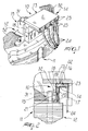
- connection assembly particularly for the windings of a stator of an electric motor, according to the invention, is generally designated by the reference numeral 10.
- the assembly 10 is applied to the stator 11 of an electric motor, which is generally designated by the reference numeral 12 and is shown only partially in the figures.
- the assembly 10 comprises a connector 13 which is constituted by a first section 14 for connection to the terminals, which are described in greater detail hereinafter, and a second section 15 for anchoring to the stator 11 of the motor 12.
- the first section 14 accommodates one or a plurality of female terminals, designated by the reference numeral 16, which are connected to one or a plurality of complementary male terminals 17 which are connected to the stator windings.
- the first section 14 is constituted by a box-like body 18 which is shaped so as to form one or a plurality of seats 19 which are electrically insulated; each seat is designed to accommodate a corresponding female terminal 16 which is shaped substantially complementarily.
- each one of the seats 19 form, for said seats, a substantially L-shaped extension, with a first connecting portion 20 which on assembly is aligned with the longitudinal extension of the male terminals 17 and is provided with a first opening 21 for the insertion of at least part of a corresponding one of the male terminals, and a second portion 22 which lies substantially at right angles to the first portion 20, is designed to support a corresponding female terminal 16 and is provided with a second end opening 23 for the insertion of the corresponding end portion of the corresponding power supply cable, designated by the reference numeral 24 in the figures.
- the body 18 has, for each one of the first portions 20, at the internal definition surface that lies opposite the second portion 22, a second retention tab 25 which is laminar and elastically flexible and is inclined with respect to the plane of arrangement of the elevation wall, which has a free end 26 which is raised with respect to the latter so as to form a locking abutment surface for part of the corresponding female terminal 16 in the opposite direction with respect to the insertion direction.
- the body 18 is shaped, for each one of the first portions 20 at the definition surface that lies opposite the one related to the first tab 25, so as to form a straight channel 27 for guiding the insertion of the corresponding female terminal 16.
- the first opening 21 is shaped substantially complementarily to the insertion portion of the corresponding male terminal 17 and is arranged so as to guide the latter in insertion in the corresponding female terminal portion 16 which is described in detail hereinafter.
- the body 18 is shaped, at one of said second openings 23, so as to form a recess 28 which is associated with retention means, described hereinafter, for accommodating in a predefined position the end portion of a corresponding power supply cable 24.
- the retention means are constituted by opposite teeth 29; however, in other cases, the operator may, in view of the particular situation of application, not use teeth 29, allowing the corresponding cable 24 to exit in a straight line, as shown in dashed lines in Figure 2.
- Each one of the recesses 28 is surrounded by a guiding border 30 which lies substantially parallel to the corresponding and opposite first portion 20.
- the second section 15 is constituted by a second hollow tab 31, with a transverse cross-section which is shaped complementarily to the insertion seat formed in the stator 11 and with a longitudinal extension which is substantially parallel to the first portion 20; the second tab 31 constitutes the seat for the thermal protection device, which is of a per se known type not shown in the figures.
- the second tab 31 is monolithic with respect to the free end of a bracket 32 which is in turn monolithic with respect to the body 18 in a position which lies opposite the position for the insertion of the power supply cables 24.
- the second tab 31, thanks to its shape and position, also allows to accommodate the thermal protection device even after connection has occurred.
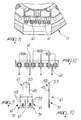
- the connector 13 also has a cover 33 with an opening and closure path of the edge-hinged type which is transverse to the path for the insertion of the power supply cables 24.
- the cover 33 is fixed and pivoted laterally to the body 18 by means of bands 34 which are monolithic thereto and are provided with a weaker region for folding.
- the cover 33 is also associated with locking means which are constituted, in this case, by monolithic teeth 35 which cantilever out from the body 18, are arranged opposite the pivoting bands 34 and are adapted to enter corresponding holes 36 (shown in dashed lines in Figure 7) which are formed at the free end of the cover 33.
- the cover is also provided with internal reinforcement ridges 37.
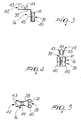
- each one of the female terminals 16 comprises a laminar body 38 which is substantially L-shaped and complementary to the corresponding seat 19 and has a third connection portion 39, which comprises a pair of first opposite wings 40 with free ends 41 which are folded toward the body 38 so as to form the insertion seat of the corresponding male terminal portion 17, and a fourth portion 42, which is provided with two pairs, respectively, of second wings 43 and third wings 44 for clinching to the stripped end region of the corresponding power supply cable 24.
- the body 38 of the female terminal 16 is shaped in opposition to the first wings 40 so as to form a linear stud 45 for guiding the insertion in the corresponding channel 27 formed in the corresponding first portion 20 of the seat 19.
- the first wings 40 are shaped so as to form folds with a circular arc-like profile which delimit an insertion section which is such as to force the corresponding male terminal 17 to perform insertion with elastic forcing.
- the second wings 43 are longer than the third wings 44.
- Each one of the male terminals 17 is constituted by a laminar body 47 which has a fifth portion 48 which is shaped so as to form a laminar tang 49 for insertion upon connection in the section formed by said first wings 40, which is radiused and monolithic with respect to a sixth portion 50 which has an end 51 for connection to the wires of the stator windings, designated by the reference numeral 52.
- the fifth portion 48 has a free end 53 which tapers outwards in order to guide insertion.
- the end 51 is provided with fifth opposite wings 54 which are folded on the plane of arrangement of the body 47 of said male terminal 17 with free ends 55 which converge at the axis of said end 51, so as to form a self-centering tapering seat 56 for a corresponding wire of the stator 11.
- the fifth wings 54 are shaped at facing edge portions 57 so as to form blades 58 which are adapted to punch through the insulating sheath of the accommodated wire.
- the end 51 has, in this case also, two pairs of third tabs 59 for retention in elevation with the free end with respect to the arrangement of the end 51.
- end 51 is laterally provided with two retention teeth 60.
- the laminar body 47 is shaped so as to form substantially two parallel ends 51 which are arranged symmetrically opposite with respect to the axis of the fifth portion 48.
- the second section 15 also comprises an auxiliary element for connection to the stator 11, which is associated with the body 18; the auxiliary element is shaped like a half box and so as to form parallel seats which are adapted for the guided connection of the end portions of the stator windings to corresponding ends 51 of the male terminals 17 inserted therein.
- the assembly 10 can be advantageously preassembled separately from the stator 11.
- connection assembly according to the invention, which allows, both during production of the electric motor and during connection thereof to the power supply, connections which are safe in terms of short-circuits or damage to the components and for the operator.
- connection assembly allows high automation both in the manufacture of the electric motor and in the manufacture of said assembly, also allowing last-minute modifications in the arrangement and setting of the connections.
- connection assembly according to the invention by virtue of its structure, allows mass-production with costs and times which are competitive with respect to connectors having similar functionalities.
- the materials and the dimensions may be any according to requirements.
Landscapes
- Engineering & Computer Science (AREA)
- Power Engineering (AREA)
- Insulation, Fastening Of Motor, Generator Windings (AREA)
- Motor Or Generator Frames (AREA)
- Manufacture Of Motors, Generators (AREA)
Applications Claiming Priority (2)
| Application Number | Priority Date | Filing Date | Title |
|---|---|---|---|
| IT2000PD000001A IT1317303B1 (it) | 2000-01-05 | 2000-01-05 | Gruppo di connessione particolarmente per gli avvolgimenti di unostatore di motore elettrico. |
| ITPD000001 | 2000-01-05 |
Publications (3)
| Publication Number | Publication Date |
|---|---|
| EP1115191A2 true EP1115191A2 (de) | 2001-07-11 |
| EP1115191A3 EP1115191A3 (de) | 2002-11-13 |
| EP1115191B1 EP1115191B1 (de) | 2008-08-27 |
Family
ID=11451739
Family Applications (1)
| Application Number | Title | Priority Date | Filing Date |
|---|---|---|---|
| EP00128111A Expired - Lifetime EP1115191B1 (de) | 2000-01-05 | 2000-12-21 | Verbindungsanordnung, insbesondere für die Statorwicklung eines Elektromotors |
Country Status (8)
| Country | Link |
|---|---|
| EP (1) | EP1115191B1 (de) |
| AT (1) | ATE406684T1 (de) |
| CZ (1) | CZ200149A3 (de) |
| DE (1) | DE60040054D1 (de) |
| HU (1) | HU226179B1 (de) |
| IT (1) | IT1317303B1 (de) |
| PL (1) | PL198656B1 (de) |
| SK (1) | SK286963B6 (de) |
Cited By (9)
| Publication number | Priority date | Publication date | Assignee | Title |
|---|---|---|---|---|
| WO2002045243A1 (en) | 2000-12-01 | 2002-06-06 | Abb Oy | Connection base |
| EP1337012A1 (de) * | 2002-02-16 | 2003-08-20 | FHP Motors GmbH | Steckeinrichtung zum elektrisch leitenden Verbinden der Wicklungsdrähte der Statorwicklungen eines Elektromotors mit zumindestens einer elektischen Leitung |
| WO2004004093A1 (ja) | 2002-07-01 | 2004-01-08 | Matsushita Electric Industrial Co., Ltd. | 電動機 |
| EP1441433A1 (de) * | 2003-01-24 | 2004-07-28 | INARCA S.p.A. | Verbindungsanordnung, insbesondere für die Statorwicklungen eines Elektromotor |
| EP1643620A3 (de) * | 2004-09-30 | 2007-09-26 | INARCA S.p.A. | Anordnung für den Anschluss der Statorwicklungen des elektrischen Motors eines Kompressors |
| DE102006032827A1 (de) * | 2006-07-14 | 2008-01-17 | Acc Germany Gmbh | Elektromotor mit einem Statorpaket |
| CN103051101A (zh) * | 2012-12-03 | 2013-04-17 | 江苏航天动力机电有限公司 | 一种低压大功率电机主接线盒 |
| CN104578551A (zh) * | 2014-12-16 | 2015-04-29 | 中国船舶重工集团公司第七一二研究所 | 一种引线模块 |
| EP3154162A1 (de) * | 2015-10-07 | 2017-04-12 | Toyota Jidosha Kabushiki Kaisha | Anschlussleistenverbindungsstruktur in elektrischer drehmaschine |
Families Citing this family (1)
| Publication number | Priority date | Publication date | Assignee | Title |
|---|---|---|---|---|
| DE102019111335A1 (de) * | 2019-05-02 | 2020-11-05 | Festool Gmbh | Antriebsmotor mit einer Anschlusseinrichtung |
Family Cites Families (4)
| Publication number | Priority date | Publication date | Assignee | Title |
|---|---|---|---|---|
| US5204565A (en) * | 1990-11-21 | 1993-04-20 | Jidosha Denki Kogyo Kabushiki Kaisha | Small-sized electric motor with connector for power supply |
| JPH08163812A (ja) * | 1994-12-07 | 1996-06-21 | Sumitomo Wiring Syst Ltd | 電気接続構造 |
| DE19606141A1 (de) * | 1996-02-20 | 1997-08-21 | Aeg Kleinmotoren Gmbh | Kabelführungsträger für einen Universalmotor |
| IT1287968B1 (it) * | 1996-10-18 | 1998-09-10 | Inarca Spa | Gruppo di connessione per gli avvolgimenti di uno statore di un motore elettrico |
-
2000
- 2000-01-05 IT IT2000PD000001A patent/IT1317303B1/it active
- 2000-12-21 EP EP00128111A patent/EP1115191B1/de not_active Expired - Lifetime
- 2000-12-21 AT AT00128111T patent/ATE406684T1/de not_active IP Right Cessation
- 2000-12-21 DE DE60040054T patent/DE60040054D1/de not_active Expired - Fee Related
-
2001
- 2001-01-03 SK SK9-2001A patent/SK286963B6/sk not_active IP Right Cessation
- 2001-01-04 CZ CZ200149A patent/CZ200149A3/cs unknown
- 2001-01-04 HU HU0100031A patent/HU226179B1/hu not_active IP Right Cessation
- 2001-01-05 PL PL344956A patent/PL198656B1/pl not_active IP Right Cessation
Cited By (13)
| Publication number | Priority date | Publication date | Assignee | Title |
|---|---|---|---|---|
| WO2002045243A1 (en) | 2000-12-01 | 2002-06-06 | Abb Oy | Connection base |
| EP1337012A1 (de) * | 2002-02-16 | 2003-08-20 | FHP Motors GmbH | Steckeinrichtung zum elektrisch leitenden Verbinden der Wicklungsdrähte der Statorwicklungen eines Elektromotors mit zumindestens einer elektischen Leitung |
| WO2004004093A1 (ja) | 2002-07-01 | 2004-01-08 | Matsushita Electric Industrial Co., Ltd. | 電動機 |
| EP1521347A4 (de) * | 2002-07-01 | 2006-02-15 | Matsushita Electric Industrial Co Ltd | Motor |
| US7202581B2 (en) | 2002-07-01 | 2007-04-10 | Matsushita Electric Industrial Co., Ltd. | Electric compressor motor having a stator core of reduced height |
| EP1441433A1 (de) * | 2003-01-24 | 2004-07-28 | INARCA S.p.A. | Verbindungsanordnung, insbesondere für die Statorwicklungen eines Elektromotor |
| EP1643620A3 (de) * | 2004-09-30 | 2007-09-26 | INARCA S.p.A. | Anordnung für den Anschluss der Statorwicklungen des elektrischen Motors eines Kompressors |
| EP2043232A3 (de) * | 2004-09-30 | 2010-11-10 | Inarca S.p.A. | Elektrisches Anschlussteil für eine direkte Verbindung zu einem elektrischen Draht und elektrischer Anschlussstecker |
| DE102006032827A1 (de) * | 2006-07-14 | 2008-01-17 | Acc Germany Gmbh | Elektromotor mit einem Statorpaket |
| CN103051101A (zh) * | 2012-12-03 | 2013-04-17 | 江苏航天动力机电有限公司 | 一种低压大功率电机主接线盒 |
| CN104578551A (zh) * | 2014-12-16 | 2015-04-29 | 中国船舶重工集团公司第七一二研究所 | 一种引线模块 |
| CN104578551B (zh) * | 2014-12-16 | 2017-05-31 | 中国船舶重工集团公司第七一二研究所 | 一种引线模块 |
| EP3154162A1 (de) * | 2015-10-07 | 2017-04-12 | Toyota Jidosha Kabushiki Kaisha | Anschlussleistenverbindungsstruktur in elektrischer drehmaschine |
Also Published As
| Publication number | Publication date |
|---|---|
| HUP0100031A3 (en) | 2002-12-28 |
| SK92001A3 (en) | 2001-09-11 |
| CZ200149A3 (cs) | 2001-08-15 |
| ATE406684T1 (de) | 2008-09-15 |
| DE60040054D1 (de) | 2008-10-09 |
| EP1115191A3 (de) | 2002-11-13 |
| PL344956A1 (en) | 2001-07-16 |
| HU226179B1 (en) | 2008-06-30 |
| PL198656B1 (pl) | 2008-07-31 |
| HU0100031D0 (en) | 2001-03-28 |
| IT1317303B1 (it) | 2003-06-16 |
| ITPD20000001A1 (it) | 2001-07-05 |
| EP1115191B1 (de) | 2008-08-27 |
| HUP0100031A2 (hu) | 2002-02-28 |
| SK286963B6 (sk) | 2009-08-06 |
Similar Documents
| Publication | Publication Date | Title |
|---|---|---|
| KR101913550B1 (ko) | 단자 설치부 | |
| GB2264811A (en) | Stator construction/winding connections in an electric motor | |
| EP1115191B1 (de) | Verbindungsanordnung, insbesondere für die Statorwicklung eines Elektromotors | |
| AU2005241611B2 (en) | Coil with a contact sleeve for electrical connection | |
| EP1995851A1 (de) | Spulenanschlussstruktur und verfahren, Leitersatz und elektrischer Motor | |
| KR102428329B1 (ko) | 열 보호기 | |
| EP1916745B1 (de) | Anordnung für den Anschluss der Statorwicklungen eines Elektromotors | |
| JP3631913B2 (ja) | シールド端子及び該シールド端子の製造方法 | |
| US4646047A (en) | Electrical coil form with connector pins | |
| EP1094569B1 (de) | Verbindungskontakt und Steckverbinder, welcher diesen Kontakt enthält | |
| EP1128482A2 (de) | Schutzgehäuse für Verbindungen mit mehradrigen elektrischen Kabeln | |
| US10056720B2 (en) | Fuse unit | |
| EP1916756A2 (de) | Anordnung zur Verbindung der elektrischen Statorwicklungen eines elektrischen Motors | |
| EP4254742A1 (de) | Elektrische maschine | |
| EP1441433B1 (de) | Verbindungsanordnung, insbesondere für die Statorwicklungen eines Elektromotor | |
| EP1398862A2 (de) | Anschlussklemme für Statorwicklungen eines Elektromotors | |
| JP2010073328A (ja) | コネクタアッセンブリ、ワイヤハーネス、並びにワイヤハーネスの製造方法 | |
| WO2025015002A1 (en) | Insert molded coil assembly | |
| JP2020188570A (ja) | 回転電機 | |
| JPH08203636A (ja) | ジョイントコネクタ | |
| JP2010049881A (ja) | 短絡回路を含むワイヤハーネス及びその製造方法 | |
| JP2005143194A (ja) | 樹脂成型品の電線引出構造 | |
| JP2003092157A (ja) | 圧接ジョイントコネクタ及び該コネクタを用いた圧接接続方法 | |
| HK1063537A (en) | Connection terminal for the windings of a stator of an electric motor | |
| KR20150068149A (ko) | 모터의 터미널 조립체 및 모터의 조립 방법 |
Legal Events
| Date | Code | Title | Description |
|---|---|---|---|
| PUAI | Public reference made under article 153(3) epc to a published international application that has entered the european phase |
Free format text: ORIGINAL CODE: 0009012 |
|
| AK | Designated contracting states |
Kind code of ref document: A2 Designated state(s): AT BE CH CY DE DK ES FI FR GB GR IE IT LI LU MC NL PT SE TR |
|
| AX | Request for extension of the european patent |
Free format text: AL;LT;LV;MK;RO;SI |
|
| PUAL | Search report despatched |
Free format text: ORIGINAL CODE: 0009013 |
|
| AK | Designated contracting states |
Kind code of ref document: A3 Designated state(s): AT BE CH CY DE DK ES FI FR GB GR IE IT LI LU MC NL PT SE TR |
|
| AX | Request for extension of the european patent |
Free format text: AL;LT;LV;MK;RO;SI |
|
| RIC1 | Information provided on ipc code assigned before grant |
Free format text: 7H 02K 3/52 A, 7H 02K 5/22 B, 7H 01R 39/32 B |
|
| 17P | Request for examination filed |
Effective date: 20030430 |
|
| AKX | Designation fees paid |
Designated state(s): AT BE CH CY DE DK ES FI FR GB GR IE IT LI LU MC NL PT SE TR |
|
| 17Q | First examination report despatched |
Effective date: 20070924 |
|
| GRAP | Despatch of communication of intention to grant a patent |
Free format text: ORIGINAL CODE: EPIDOSNIGR1 |
|
| GRAS | Grant fee paid |
Free format text: ORIGINAL CODE: EPIDOSNIGR3 |
|
| GRAA | (expected) grant |
Free format text: ORIGINAL CODE: 0009210 |
|
| AK | Designated contracting states |
Kind code of ref document: B1 Designated state(s): AT BE CH CY DE DK ES FI FR GB GR IE IT LI LU MC NL PT SE TR |
|
| REG | Reference to a national code |
Ref country code: GB Ref legal event code: FG4D |
|
| REG | Reference to a national code |
Ref country code: CH Ref legal event code: EP |
|
| REG | Reference to a national code |
Ref country code: IE Ref legal event code: FG4D |
|
| REF | Corresponds to: |
Ref document number: 60040054 Country of ref document: DE Date of ref document: 20081009 Kind code of ref document: P |
|
| PG25 | Lapsed in a contracting state [announced via postgrant information from national office to epo] |
Ref country code: NL Free format text: LAPSE BECAUSE OF FAILURE TO SUBMIT A TRANSLATION OF THE DESCRIPTION OR TO PAY THE FEE WITHIN THE PRESCRIBED TIME-LIMIT Effective date: 20080827 Ref country code: ES Free format text: LAPSE BECAUSE OF FAILURE TO SUBMIT A TRANSLATION OF THE DESCRIPTION OR TO PAY THE FEE WITHIN THE PRESCRIBED TIME-LIMIT Effective date: 20081208 |
|
| PG25 | Lapsed in a contracting state [announced via postgrant information from national office to epo] |
Ref country code: FI Free format text: LAPSE BECAUSE OF FAILURE TO SUBMIT A TRANSLATION OF THE DESCRIPTION OR TO PAY THE FEE WITHIN THE PRESCRIBED TIME-LIMIT Effective date: 20080827 Ref country code: AT Free format text: LAPSE BECAUSE OF FAILURE TO SUBMIT A TRANSLATION OF THE DESCRIPTION OR TO PAY THE FEE WITHIN THE PRESCRIBED TIME-LIMIT Effective date: 20080827 |
|
| PG25 | Lapsed in a contracting state [announced via postgrant information from national office to epo] |
Ref country code: BE Free format text: LAPSE BECAUSE OF FAILURE TO SUBMIT A TRANSLATION OF THE DESCRIPTION OR TO PAY THE FEE WITHIN THE PRESCRIBED TIME-LIMIT Effective date: 20080827 |
|
| PG25 | Lapsed in a contracting state [announced via postgrant information from national office to epo] |
Ref country code: DK Free format text: LAPSE BECAUSE OF FAILURE TO SUBMIT A TRANSLATION OF THE DESCRIPTION OR TO PAY THE FEE WITHIN THE PRESCRIBED TIME-LIMIT Effective date: 20080827 |
|
| PG25 | Lapsed in a contracting state [announced via postgrant information from national office to epo] |
Ref country code: PT Free format text: LAPSE BECAUSE OF FAILURE TO SUBMIT A TRANSLATION OF THE DESCRIPTION OR TO PAY THE FEE WITHIN THE PRESCRIBED TIME-LIMIT Effective date: 20090127 |
|
| PLBE | No opposition filed within time limit |
Free format text: ORIGINAL CODE: 0009261 |
|
| STAA | Information on the status of an ep patent application or granted ep patent |
Free format text: STATUS: NO OPPOSITION FILED WITHIN TIME LIMIT |
|
| PG25 | Lapsed in a contracting state [announced via postgrant information from national office to epo] |
Ref country code: MC Free format text: LAPSE BECAUSE OF NON-PAYMENT OF DUE FEES Effective date: 20081231 |
|
| REG | Reference to a national code |
Ref country code: CH Ref legal event code: PL |
|
| 26N | No opposition filed |
Effective date: 20090528 |
|
| GBPC | Gb: european patent ceased through non-payment of renewal fee |
Effective date: 20081221 |
|
| REG | Reference to a national code |
Ref country code: IE Ref legal event code: MM4A |
|
| REG | Reference to a national code |
Ref country code: FR Ref legal event code: ST Effective date: 20090831 |
|
| PG25 | Lapsed in a contracting state [announced via postgrant information from national office to epo] |
Ref country code: CH Free format text: LAPSE BECAUSE OF NON-PAYMENT OF DUE FEES Effective date: 20081231 Ref country code: DE Free format text: LAPSE BECAUSE OF NON-PAYMENT OF DUE FEES Effective date: 20090701 Ref country code: IE Free format text: LAPSE BECAUSE OF NON-PAYMENT OF DUE FEES Effective date: 20081221 Ref country code: LI Free format text: LAPSE BECAUSE OF NON-PAYMENT OF DUE FEES Effective date: 20081231 |
|
| PG25 | Lapsed in a contracting state [announced via postgrant information from national office to epo] |
Ref country code: GB Free format text: LAPSE BECAUSE OF NON-PAYMENT OF DUE FEES Effective date: 20081221 |
|
| PG25 | Lapsed in a contracting state [announced via postgrant information from national office to epo] |
Ref country code: SE Free format text: LAPSE BECAUSE OF FAILURE TO SUBMIT A TRANSLATION OF THE DESCRIPTION OR TO PAY THE FEE WITHIN THE PRESCRIBED TIME-LIMIT Effective date: 20081127 |
|
| PG25 | Lapsed in a contracting state [announced via postgrant information from national office to epo] |
Ref country code: FR Free format text: LAPSE BECAUSE OF NON-PAYMENT OF DUE FEES Effective date: 20081231 |
|
| PG25 | Lapsed in a contracting state [announced via postgrant information from national office to epo] |
Ref country code: LU Free format text: LAPSE BECAUSE OF NON-PAYMENT OF DUE FEES Effective date: 20081221 |
|
| PG25 | Lapsed in a contracting state [announced via postgrant information from national office to epo] |
Ref country code: CY Free format text: LAPSE BECAUSE OF FAILURE TO SUBMIT A TRANSLATION OF THE DESCRIPTION OR TO PAY THE FEE WITHIN THE PRESCRIBED TIME-LIMIT Effective date: 20080827 |
|
| PG25 | Lapsed in a contracting state [announced via postgrant information from national office to epo] |
Ref country code: TR Free format text: LAPSE BECAUSE OF FAILURE TO SUBMIT A TRANSLATION OF THE DESCRIPTION OR TO PAY THE FEE WITHIN THE PRESCRIBED TIME-LIMIT Effective date: 20080827 |
|
| PG25 | Lapsed in a contracting state [announced via postgrant information from national office to epo] |
Ref country code: GR Free format text: LAPSE BECAUSE OF FAILURE TO SUBMIT A TRANSLATION OF THE DESCRIPTION OR TO PAY THE FEE WITHIN THE PRESCRIBED TIME-LIMIT Effective date: 20081128 |
|
| PGFP | Annual fee paid to national office [announced via postgrant information from national office to epo] |
Ref country code: IT Payment date: 20190916 Year of fee payment: 20 |