EP1120217A2 - Verfahren und Vorrichtung zum Schneiden von Stabwerkstücken - Google Patents
Verfahren und Vorrichtung zum Schneiden von Stabwerkstücken Download PDFInfo
- Publication number
- EP1120217A2 EP1120217A2 EP01101454A EP01101454A EP1120217A2 EP 1120217 A2 EP1120217 A2 EP 1120217A2 EP 01101454 A EP01101454 A EP 01101454A EP 01101454 A EP01101454 A EP 01101454A EP 1120217 A2 EP1120217 A2 EP 1120217A2
- Authority
- EP
- European Patent Office
- Prior art keywords
- grindstone
- ingot
- metal
- strip
- bonded
- Prior art date
- Legal status (The legal status is an assumption and is not a legal conclusion. Google has not performed a legal analysis and makes no representation as to the accuracy of the status listed.)
- Granted
Links
Images


Classifications
-
- B—PERFORMING OPERATIONS; TRANSPORTING
- B28—WORKING CEMENT, CLAY, OR STONE
- B28D—WORKING STONE OR STONE-LIKE MATERIALS
- B28D5/00—Fine working of gems, jewels, crystals, e.g. of semiconductor material; apparatus or devices therefor
- B28D5/0058—Accessories specially adapted for use with machines for fine working of gems, jewels, crystals, e.g. of semiconductor material
-
- B—PERFORMING OPERATIONS; TRANSPORTING
- B24—GRINDING; POLISHING
- B24B—MACHINES, DEVICES, OR PROCESSES FOR GRINDING OR POLISHING; DRESSING OR CONDITIONING OF ABRADING SURFACES; FEEDING OF GRINDING, POLISHING, OR LAPPING AGENTS
- B24B27/00—Other grinding machines or devices
- B24B27/06—Grinders for cutting-off
-
- B—PERFORMING OPERATIONS; TRANSPORTING
- B24—GRINDING; POLISHING
- B24B—MACHINES, DEVICES, OR PROCESSES FOR GRINDING OR POLISHING; DRESSING OR CONDITIONING OF ABRADING SURFACES; FEEDING OF GRINDING, POLISHING, OR LAPPING AGENTS
- B24B53/00—Devices or means for dressing or conditioning abrasive surfaces
- B24B53/001—Devices or means for dressing or conditioning abrasive surfaces involving the use of electric current
-
- B—PERFORMING OPERATIONS; TRANSPORTING
- B28—WORKING CEMENT, CLAY, OR STONE
- B28D—WORKING STONE OR STONE-LIKE MATERIALS
- B28D5/00—Fine working of gems, jewels, crystals, e.g. of semiconductor material; apparatus or devices therefor
- B28D5/04—Fine working of gems, jewels, crystals, e.g. of semiconductor material; apparatus or devices therefor by tools other than rotary type, e.g. reciprocating tools
- B28D5/042—Fine working of gems, jewels, crystals, e.g. of semiconductor material; apparatus or devices therefor by tools other than rotary type, e.g. reciprocating tools by cutting with blades or wires mounted in a reciprocating frame
-
- Y—GENERAL TAGGING OF NEW TECHNOLOGICAL DEVELOPMENTS; GENERAL TAGGING OF CROSS-SECTIONAL TECHNOLOGIES SPANNING OVER SEVERAL SECTIONS OF THE IPC; TECHNICAL SUBJECTS COVERED BY FORMER USPC CROSS-REFERENCE ART COLLECTIONS [XRACs] AND DIGESTS
- Y10—TECHNICAL SUBJECTS COVERED BY FORMER USPC
- Y10T—TECHNICAL SUBJECTS COVERED BY FORMER US CLASSIFICATION
- Y10T83/00—Cutting
- Y10T83/687—By tool reciprocable along elongated edge
Definitions
- the present invention relates to an apparatus and method for cutting ingots such as single crystal ingots of SiC etc., used in hard electronics.
- Hard electronics generally means solid state electronics based on wide-gap semiconductors with physical properties better than those of silicon, such as SiC and diamond, which have harder specifications than those of silicon.
- the band gaps of SiC and diamond used in hard electronics are in the range of 2.5 to 6 eV compared to the 1.1 eV of silicon.
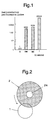
- the Johnson index for a high-speed, large-output device is one of the performance indexes used in hard electronics. As shown in Fig. 1, if the index is assumed to be 1 for silicon, those of the semiconductors used in hard electronics are a hundred to a thousand times greater.
- semiconductors based on hard electronics are considered to be very hopeful as replacements for conventional silicon semiconductors in various fields such as high energy electronics typically used for power devices, electronics for information technologies based mainly on millimeter waves and microwave telecommunications and electronics for extreme environments including nuclear power, geothermal heat and space technologies.
- the ingot must be cut into flat wafers in the same way as is done conventionally.
- the ingot is cut using either (1) an outer edge cutter, (2) an inner edge cutter or (3) a wire saw.
- the outer edge cutter is shown typically in Fig. 2.
- a thin disk-shaped cutter with a cutting edge 2 is rotated at a high speed about its center shaft 2a, and its outer edge cuts the ingot 1.
- This type of cutter has been used conventionally to cut single crystals of SiC.
- the thickness of the cutting edge is about 0.8 mm and the diameter of the disk is about 8 inches (about 200 mm). Therefore the thickness of the material lost in cutting (corresponding to the edge thickness + runout) is larger than the thickness of the product (about 0.3 mm). That is, the problem concerns the loss of a large amount of expensive single crystal SiC.
- the diameter of a single crystal SiC ingot has been increased to 4 inches or more (about 100 mm or more) as there is a demand for large devices and the manufacturing technology has advanced.
- the diameter of the cutting disk is about 10 inches (about 250 mm) and the size of the cut is about 1.0 mm, so the losses become much greater.
- the inner edge cutter is shown schematically in Fig. 3.
- a thin cutting disk 3 with a hole 3a at the center is rotated at a high speed, and the ingot 1 is cut by grinding material electrolytically deposited on the inner periphery.
- the cutting disk 3 is a metal plate with a thickness as small as 0.2 to 0.3 mm, and the outer periphery is supported by another ring member (not illustrated) in order to keep the plate flat.
- a fine wire 4 0.2 to 0.3 mm in diameter, is stretched between the guide pulleys 4a and pulled across in an endless manner.
- the ingot is cut by slurry containing grinding grains supplied between the ingot 1 and the wire 4. Because this type of cutting method cuts slowly with the help of a slurry, normally a number of wafers (4 to 8 wafers) are cut simultaneously by one length of wire 4 as shown in Fig. 4.
- this cutting means causes only a small amount of cutting losses, when a hard single crystal of SiC is cut, the wire is rapidly consumed and breaks frequently. In particular, the wire is often cut at the outer periphery of the ingot 1 because of considerable vibrations. Once the wire breaks, the single crystal of SiC being cut is totally lost, so the large loss of an ingot is the problem. Also, a single crystal SiC ingot is hard and difficult to cut, so that a large amount of slurry is required, resulting in a high cost.
- an object of the present invention aims at solving the various problems and satisfying demands.
- an object of the present invention is to provide an apparatus and method for cutting ingots such that a large, hard and refractory ingot can be cut efficiently with a small amount of cutting losses, a small degree of warping and thickness irregularity on the finished surface, small roughness of the cut surface, minimal damage to the crystal during processing, low operating costs, and small manpower requirements.
- the ingot cutting apparatus offered by the present invention is provided with a thin strip-shaped grindstone (12), a tensioning mechanism (14) that applies a tension to the above-mentioned strip-shaped grindstone to keep the grindstone flat, a reciprocating device (16) to move the strip-shaped grindstone backwards and forwards in the longitudinal direction, and a cutting device (18) that moves the strip-shaped grindstone in the direction of the diameter of the cylindrical ingot (1).
- a method of cutting ingots is provided.
- a tension is applied to thin strip-shaped grindstone (12) to maintain the grindstone flat, the strip shaped grindstone is moved backwards and forwards in the longitudinal direction, the strip-shaped grindstone is moved in the radial direction of the cylindrical ingot (1) and the ingot is cut.
- the ingot can be cut efficiently even if it is large in diameter and hard to cut.
- the cutting tool strip-shaped grindstone
- the strip-shaped grindstone is smaller and cheaper, so the running cost can be reduced.
- a thin strip-shaped grindstone with a thickness for example, of 0.2 to 0.3 mm can be used, so that the runout of the grindstone can be reduced. Therefore, the cutting losses can be decreased, and the warping or uneven thickness of the finished surface can also be decreased.
- the strip shaped grindstone is more resistant to breakage than a wire, the loss of an expensive ingot (for instance, of a single crystal of SiC) can be greatly reduced.
- the tensioning mechanism (14) is composed of a pair of fixing components (14a) that are attached to both ends of the strip-shaped grindstone (12), and a tensioning component (14b) that pulls the above-mentioned fixing components in the longitudinal direction of the strip-shaped grindstone.
- the reciprocating device (16) is comprised of a double-action bed that drives the above-mentioned tensioning mechanism (14) backwards and forwards in the horizontal or vertical direction.
- the cutting device (18) is composed of a moving device that holds the ingot (1) and drives it in a direction parallel to the plane of the strip-shaped grindstone.
- This configuration simplifies the structure of the apparatus, reduces machine failures, increases the operating efficiency, reduces running costs, can be easily automated, and saves manpower.
- the above-mentioned tensioning mechanism (14) should preferably support a number of strip-shaped grindstones (12) mounted parallel to each other.
- Such a configuration as described above provides for multiple cutting (the ingot is cut at a number of locations simultaneously) using a plurality of strip-shaped grindstones, so the configuration can also increase the rate of cutting.
- the strip-shaped grindstone (12) is a metal-bonded grindstone, and is provided with at least one pair of electrodes (23) arranged on both sides of the ingot in the radial direction, separated from both surfaces of the metal-bonded grindstone, a means (22) for applying a voltage to supply DC voltage pulses to the above-mentioned electrodes with the metal-bonded grindstone as the positive electrode, and a means (24) of feeding processing fluid to supply a conducting processing fluid (25) between the metal-bonded grindstone and the above-mentioned electrodes.
- a minimum of one pair of electrodes (23) are arranged adjacent to both surfaces of the metal-bonded grindstone on both sides of the ingot in the radial direction.
- DC voltage pulses are applied to the electrodes with the metal-bonded grindstone as the positive electrode, and at the same time, conducting processing fluid (25) is supplied between the metal-bonded grindstone and the electrodes, the cylindrical ingot is cut by the metal-bonded grindstone, and simultaneously, both surfaces of the grindstone are dressed electrolytically on both sides thereof.
- so-called electrolytic in-process dressing grinding can be carried out, wherein an ingot is cut while both surfaces of the metal-bonded grindstone are electrolytically dressed.
- the grinding grains are sharpened, so that even a hard single crystal SiC ingot can be cut efficiently.
- microscopic grinding grains can be used and the cut surface can be finished to give an excellent flat surface with a near-mirror surface finish.
- the amount of subsequent processing polishing can be greatly reduced, and also processing damage to the crystal can be minimized.
- the above-mentioned strip-shaped grindstone (12) is composed of a strip of metal (13) and a metal-bonded grindstone (12a) formed on the edge thereof by electric casting. With this configuration, a metal-bonded grindstone that can withstand the tension needed to keep the grindstone flat can be easily manufactured.
- Fig. 1 compares the performance of hard electronic substances to conventional Si.
- Fig. 2 is a conceptual view of a conventional outer edge cutter.
- Fig. 3 shows a conventional inner edge cutter.
- Fig. 4 shows a conventional wire saw.
- Fig. 5 is a schematic view of an ingot cutting apparatus according to the present invention.
- Figs. 6A and 6B show the major components of the apparatus shown in Fig. 5.
- Figs. 7A to 7C illustrate the operation of the apparatus according to the present invention.
- Fig. 8 shows another embodiment of the ingot cutting apparatus according to the present invention.
- Fig. 5 shows a typical configuration of the ingot cutting apparatus according to the present invention.
- the ingot cutting apparatus 10 according to the present invention is provided with a thin strip-shaped grindstone 12, a tensioning mechanism 14 that applies a tension to the strip-shaped grindstone 12 and maintains the grindstone flat, a reciprocating device 16 that moves the strip-shaped grindstone 12 backwards and forwards in the longitudinal direction, and a cutting device 18 that moves the strip-shaped grindstone 12 in the radial direction of the cylindrical ingot 1.
- the cylindrical ingot 1 is, in this embodiment, a single crystal SiC ingot with an outer diameter of about 4 inches.
- the present invention is not limited to the ingot, but is applicable also to various ingots including silicon ingots.
- the strip-shaped grindstone 12 is composed of a strip of metal 13 and a metal-bonded grindstone 12a formed along the edge thereof, in this embodiment.
- the strip of metal 13 is, for instance, a metal sheet as thin as 0.2 to 0.3 mm.
- the metal-bonded grindstone 12a is produced by electrically casting grinding grains onto part of the strip of metal 13, and the total thickness is similar to or slightly larger than the strip of metal 13.
- This metal-bonded grindstone 12a is composed of grinding grains (for instance, diamond grinding grains) and a metal-bonding material and is formed by electric casting. The size of the grinding grains should be as small as possible for the purpose of producing an excellent flat surface with an almost mirror surface finish.
- the preferred grain diameter is 2 ⁇ m (equivalent to granularity #8000) to 5 nm (equivalent to granularity #3,000,000) for practical applications.
- coarser grains such as #325 to 4 ⁇ m (corresponding to #4000) can also be used. By using coarse grinding grains, more efficient cutting can be achieved, and by using fine grinding grains, a nearly mirror surface finish can be attained.
- the present invention should not be limited only to the embodiments described above, but the strip-shaped grindstone 12 can also be an ordinary grindstone instead of a metal-bonded grindstone.
- the tensioning mechanism 14 is composed of a pair of fixing components 14a that sandwich and fix both ends of the strip-shaped grindstone 12, and a tensioning component 14b that pulls the strip-shaped grindstone 12 outwards in the longitudinal direction (in this example, in the horizontal direction).
- the fixing members 14a are comprised of flat plate components 15a in this embodiment, that hold and are fixed to both ends of the strip-shaped grindstone 12, from both sides. Through-holes are provided in the fixing components 14a, and both ends of strip-shaped grindstone 12 can be securely sandwiched and fixed to the flat plate components 15a by tightening nuts and bolts etc. inserted through the holes.
- the pulling components 14b in this embodiment are horizontal bolts that attach the vertical components 15b to the flat plate components 15a.
- the flat plate components 15a are pulled outwards in the longitudinal direction (outwards in the horizontal direction), and the tension in the strip-shaped grindstone 12 is adjusted, thereby the strip-shaped grindstone 12 can be held in a flat condition.
- the reciprocating device 16 is a double-action bed that moves the tensioning mechanism 14 backwards and forwards horizontally in this example.
- the pair of vertical components 15b are fixed on the top of the double-action bed.
- This double-action bed is guided by a linear guide, not illustrated, and is driven horizontally by a reciprocating device.
- the cutting device 18 is, in this embodiment, a moving device that supports the ingot 1 and moves it in the direction parallel to the strip-shaped grindstone.
- the moving device 18 is configured with a work base 19a that carries the ingot 1, and a vertical drive mechanism (not illustrated) that lifts the work base 19a in the upward direction.
- a carbon block 6 is bonded to the bottom of the cylindrical ingot 1, and the carbon block is fixed to the upper surface of the work base 19a.
- the cutting device 18 can also be configured so as to move the strip-shaped grindstone 12 in the direction parallel to the surface thereof, instead of moving the ingot 1.
- Figs. 6A and 6B show the arrangement of the major parts shown in Fig. 5.
- Fig. 6A is a front view
- Fig. 6B is a sectional view along the line B-B.
- the ingot cutting apparatus 10 according to the present invention is further provided with at least one pair of electrodes 23, a means of applying a voltage 22, and a means of feeding processing fluid 24.
- a minimum of one pair of electrodes 23, arranged one on each side of the ingot 1, are provided with a gap between the electrode and each side of the metal-bonded grindstone 12a. That is, in this example, a pair of electrodes 23 with U-shaped cross sections are supported by lifting devices 26 (for instance, pulsed cylinders) attached to the upper surface of the work base 19a. In addition, a lower-surface sensor 27 for detecting the position of the bottom of the strip-shaped grindstone 12 is fixed on the work base 19a.
- the position of the bottom of the grindstone is detected by the lower-surface sensor 27, and subsequently the pair of electrodes 23 are lowered by the lifting devices 26, so that the electrodes 23 on diametrically opposite sides of the ingot 1 are maintained close to the predetermined gaps from each side and the bottom of the metal-bonded grindstone 12a.
- the means of applying a voltage 22 is composed of a power supply 22a, a connector 22b, and a power cable 22c.
- DC voltage pulses are applied between the metal-bonded grindstone 12a and electrodes 23, with the grindstone as the positive electrode supplied through the connector 22b.
- the power supply 22a should preferably be a constant-current ELID power supply that can supply DC pulses.
- the means of feeding processing fluid 24 is provided with nozzles 24a directed towards the gaps between the metal-bonded grindstone 12a and the electrodes 23 and the place where the metal-bonded grindstone 12a contacts the ingot 1, and processing fluid lines 24b for feeding a conducting processing fluid 25 to the nozzles 24a, and supplies the conducting processing fluid 25 to the gap between the grindstone 11 and the place where it contact the ingot 1.
- Figs. 7A to 7C illustrate the operation of the apparatus according to the present invention.
- Fig. 7A shows the state in which the reciprocating device 16 has moved the metal-bonded grindstone 12a towards the right hand side of the figure.
- Fig. 7B shows an intermediate location.
- Fig. 7C represents the state in which it has moved to the left. That is, the metal-bonded grindstone 12a is given a reciprocating motion in the horizontal direction relative to the ingot 1 by the reciprocating device 16, and continuously repeats the movements as shown in Figs. 7A ⁇ 7B ⁇ 7C ⁇ 7B ⁇ 7A.
- a thin strip-shaped grindstone 12 is held under tension and maintained in a flat state, and is given a longitudinal reciprocating motion as shown in Figs. 7A to 7C, while the strip-shaped grindstone 12 is moved perpendicularly to the cylindrical ingot 1 and continuously cuts the ingot.
- a metal-bonded grindstone is used as the strip-shaped grindstone 12, and as shown in Figs. 7A to 7C, at least one pair of electrodes 23 are disposed, one on each side of the ingot 1 with gaps between them and both surfaces of the metal-bonded grindstone 12a, and using the metal-bonded grindstone 12a as the positive electrode, DC voltage pulses are applied between the positive electrode and the electrodes 23, and at the same time, a conducting processing fluid 25 is supplied between the metal-bonded grindstone 12a and the electrodes 23.
- the metal-bonded grindstone 12a cuts the cylindrical ingot 1, and simultaneously, the surfaces of the metal-bonded grindstone 12 are electrically dressed on both sides.
- Fig. 8 shows another configuration of the ingot cutting apparatus according to the present invention.
- the tensioning mechanism 14 holds a plurality of strip-shaped grindstones 12 (in this example, three grindstones) parallel to each other, and the plurality of strip-shaped grindstones cut an ingot at multiple positions, thereby the cutting speed is further increased.
- the other details of this configuration are the same as those shown in Figs. 5 to 7.
- the strip-shaped grindstone 12 moves with a longitudinal reciprocating motion and cuts the cylindrical ingot 1
- large diameter, hard, refractory ingots for instance, single crystal SiC ingots
- the edge cutting (strip-shaped) grindstone by the present invention is smaller and cheaper, so running costs can be reduced.
- strip-shaped grindstone 12 is kept under tension and maintained flat, a strip-shaped grindstone as thin as, for instance, 0.2 to 0.3 mm can be used. Because the runout of the grindstone can be made small, there is less cutting waste than in conventional methods, and warping and uneven thickness of the finished surface can also be reduced. In addition the strip-shaped grindstone 12 is less likely to be broken than a wire saw, so that costly losses of ingots (single crystal SiC, for example) can be remarkably decreased.
- the first embodiment of the apparatus and methods according to the present invention can use the so-called electrolytic in-process dressing (ELID) grinding method wherein both surfaces of the metal-bonded grindstone 12a can be electrolytically dressed while the ingot 1 is being cut. Therefore, as the grinding grains are sharpened by electrolytic dressing, even a hard, single crystal SiC ingot can be efficiently cut.
- ELD electrolytic in-process dressing
- the surface of the metal-bonded grindstone can be very precisely sharpened by means of this electrolytic dressing, fine grinding grains can be used, so the cut surface can be finished to be nearly as flat as a mirror surface.
- the need for subsequent processing polishing
- damage to the crystal during processing can be reduced to a minimum.
- the ingot cutting apparatus and cutting method according to the present invention provide various advantages such as that a large diameter hard, refractory ingot can be efficiently cut with a small amount of cutting waste, reduced warping and uneven thickness of the finished surface, small roughness of the cut surface, small amount of damage to the crystal during processing, reduced running costs, and reduction in manpower requirements.
Landscapes
- Engineering & Computer Science (AREA)
- Mechanical Engineering (AREA)
- Processing Of Stones Or Stones Resemblance Materials (AREA)
- Mechanical Treatment Of Semiconductor (AREA)
- Polishing Bodies And Polishing Tools (AREA)
- Finish Polishing, Edge Sharpening, And Grinding By Specific Grinding Devices (AREA)
- Accessories And Tools For Shearing Machines (AREA)
Applications Claiming Priority (2)
| Application Number | Priority Date | Filing Date | Title |
|---|---|---|---|
| JP2000016518 | 2000-01-26 | ||
| JP2000016518A JP4258592B2 (ja) | 2000-01-26 | 2000-01-26 | インゴット切断装置とその方法 |
Publications (3)
| Publication Number | Publication Date |
|---|---|
| EP1120217A2 true EP1120217A2 (de) | 2001-08-01 |
| EP1120217A3 EP1120217A3 (de) | 2004-03-03 |
| EP1120217B1 EP1120217B1 (de) | 2006-05-31 |
Family
ID=18543642
Family Applications (1)
| Application Number | Title | Priority Date | Filing Date |
|---|---|---|---|
| EP20010101454 Expired - Lifetime EP1120217B1 (de) | 2000-01-26 | 2001-01-23 | Verfahren und Vorrichtung zum Schneiden von Stabwerkstücken |
Country Status (5)
| Country | Link |
|---|---|
| US (1) | US6539932B2 (de) |
| EP (1) | EP1120217B1 (de) |
| JP (1) | JP4258592B2 (de) |
| AT (1) | ATE327876T1 (de) |
| DE (1) | DE60120001T2 (de) |
Cited By (2)
| Publication number | Priority date | Publication date | Assignee | Title |
|---|---|---|---|---|
| CN110303609A (zh) * | 2019-07-12 | 2019-10-08 | 芯盟科技有限公司 | 晶圆切削机台及晶圆边缘切削方法 |
| CN110653949A (zh) * | 2019-09-30 | 2020-01-07 | 泽鼎石业(天津)有限公司 | 一种石材开槽机 |
Families Citing this family (10)
| Publication number | Priority date | Publication date | Assignee | Title |
|---|---|---|---|---|
| EP1634225A4 (de) * | 2004-03-10 | 2008-01-16 | Nice Systems Ltd | Vorrichtung und verfahren zum erzeugen eines follow-up auf inhaltsbasis |
| JP2007118581A (ja) * | 2005-09-28 | 2007-05-17 | Hiroshi Ishizuka | 硬脆性材料の薄板及びその製造方法 |
| JP5217918B2 (ja) * | 2008-11-07 | 2013-06-19 | 信越半導体株式会社 | インゴット切断装置及び切断方法 |
| DE102010018570B4 (de) * | 2010-04-28 | 2017-06-08 | Siltronic Ag | Verfahren zur Herstellung einer Vielzahl von Halbleiterscheiben durch Bearbeiten eines Einkristalls |
| KR101137534B1 (ko) * | 2011-05-23 | 2012-04-20 | 주식회사동아쏠라 | 슬림 로드 커터 |
| CN103182749A (zh) * | 2011-12-29 | 2013-07-03 | 北京有色金属研究总院 | 一种薄板状多晶材料的切割方法 |
| JP2017503692A (ja) * | 2013-12-30 | 2017-02-02 | ビーピー・コーポレーション・ノース・アメリカ・インコーポレーテッド | 岩石特性の直接数値シミュレーションのためのサンプル準備装置 |
| JP6270921B2 (ja) * | 2016-06-28 | 2018-01-31 | 株式会社リード | ブレードのドレッシング機構を備えた切削装置 |
| EP3346017B1 (de) * | 2017-01-10 | 2021-09-15 | Heraeus Deutschland GmbH & Co. KG | Verfahren zum schneiden von refraktärmetallen |
| CN108406451B (zh) * | 2018-05-21 | 2024-05-14 | 浙江工业大学 | 一种球形面抛光精磨装置及方法 |
Family Cites Families (13)
| Publication number | Priority date | Publication date | Assignee | Title |
|---|---|---|---|---|
| US4160397A (en) * | 1977-10-17 | 1979-07-10 | Milo Bertini | Saw blade construction and method of making same |
| JPS5859566A (ja) | 1981-10-02 | 1983-04-08 | Yuasa Battery Co Ltd | 鉛蓄電池 |
| DE3446564A1 (de) * | 1984-12-20 | 1986-07-03 | Heliotronic Forschungs- und Entwicklungsgesellschaft für Solarzellen-Grundstoffe mbH, 8263 Burghausen | Verfahren zum herstellen von klingenpaketen fuer das zertrennen von kristallstaeben in scheiben |
| JPS62264869A (ja) | 1986-05-12 | 1987-11-17 | Matsushita Electric Ind Co Ltd | 精密加工用砥石 |
| US4920946A (en) * | 1987-03-03 | 1990-05-01 | Applied Magnetic Lab. Co., Ltd. | Blade cutting apparatus for hard brittle material |
| JPH01175166A (ja) | 1987-12-28 | 1989-07-11 | Shin Kobe Electric Mach Co Ltd | 鉛蓄電池用極柱の製造方法 |
| DE3931837C1 (de) * | 1989-09-23 | 1991-03-14 | Peter G Werner | |
| JP2616149B2 (ja) * | 1990-06-12 | 1997-06-04 | 日本電気株式会社 | 電解ドレッシング研削装置 |
| JP3008560B2 (ja) * | 1991-06-28 | 2000-02-14 | 日本電気株式会社 | 研削切断装置 |
| JPH05104438A (ja) * | 1991-10-17 | 1993-04-27 | Toyo A Tec Kk | スライシング装置における目立てドレス方法及びその装置 |
| JPH05104437A (ja) * | 1991-10-17 | 1993-04-27 | Toyo A Tec Kk | スライシング装置における反り制御方法及びその装置 |
| CH691673A5 (de) * | 1995-09-08 | 2001-09-14 | Tokyo Seimitsu Co Ltd | Vorrichtung zur Erfassung eines Drahtführungsfehlers an einer Drahtsäge. |
| JPH09187815A (ja) | 1996-01-09 | 1997-07-22 | Olympus Optical Co Ltd | 液中切断方法および装置 |
-
2000
- 2000-01-26 JP JP2000016518A patent/JP4258592B2/ja not_active Expired - Lifetime
-
2001
- 2001-01-23 AT AT01101454T patent/ATE327876T1/de not_active IP Right Cessation
- 2001-01-23 DE DE2001620001 patent/DE60120001T2/de not_active Expired - Fee Related
- 2001-01-23 EP EP20010101454 patent/EP1120217B1/de not_active Expired - Lifetime
- 2001-01-25 US US09/768,795 patent/US6539932B2/en not_active Expired - Lifetime
Cited By (3)
| Publication number | Priority date | Publication date | Assignee | Title |
|---|---|---|---|---|
| CN110303609A (zh) * | 2019-07-12 | 2019-10-08 | 芯盟科技有限公司 | 晶圆切削机台及晶圆边缘切削方法 |
| CN110303609B (zh) * | 2019-07-12 | 2021-08-03 | 芯盟科技有限公司 | 晶圆切削机台及晶圆边缘切削方法 |
| CN110653949A (zh) * | 2019-09-30 | 2020-01-07 | 泽鼎石业(天津)有限公司 | 一种石材开槽机 |
Also Published As
| Publication number | Publication date |
|---|---|
| US6539932B2 (en) | 2003-04-01 |
| DE60120001D1 (de) | 2006-07-06 |
| EP1120217B1 (de) | 2006-05-31 |
| JP2001205623A (ja) | 2001-07-31 |
| EP1120217A3 (de) | 2004-03-03 |
| JP4258592B2 (ja) | 2009-04-30 |
| ATE327876T1 (de) | 2006-06-15 |
| DE60120001T2 (de) | 2006-09-21 |
| US20010017130A1 (en) | 2001-08-30 |
Similar Documents
| Publication | Publication Date | Title |
|---|---|---|
| US6539932B2 (en) | Apparatus and method for cutting ingots | |
| US8968054B2 (en) | Method for cooling a workpiece made of semiconductor material during wire sawing | |
| CN101870085A (zh) | 同时研磨多个半导体晶片的方法 | |
| JP2011526215A (ja) | ワイヤーソー切断装置 | |
| JP2014162206A (ja) | スクライビングホイール、ホルダーユニット、スクライブ装置及びスクライビングホイールの製造方法 | |
| US20040083863A1 (en) | Method for cutting hard and brittle material | |
| JP3052201B2 (ja) | 精密平面加工機械 | |
| JP2015027728A (ja) | ワイヤソーデバイスおよびその製造方法 | |
| KR102419285B1 (ko) | 다중 블레이드 절단장치 | |
| US6537139B2 (en) | Apparatus and method for ELID grinding a large-diameter workpiece to produce a mirror surface finish | |
| US6352071B1 (en) | Apparatus and method for reducing bow and warp in silicon wafers sliced by a wire saw | |
| JP2007030155A (ja) | 窒化物半導体結晶の加工方法 | |
| KR101303552B1 (ko) | 반도체 웨이퍼의 양면을 화학적으로 그라인딩하는 방법 | |
| JP5127209B2 (ja) | 半導体基板の製造方法 | |
| US20240234125A9 (en) | Method for producing discs from a cylindrical rod made of a semiconductor material | |
| JPH09216223A (ja) | 糸鋸引き装置 | |
| JP2003159642A (ja) | ワーク切断方法およびマルチワイヤソーシステム | |
| CN210256793U (zh) | 一种大尺寸碳化硅晶片金刚石线切割机床 | |
| JP4262922B2 (ja) | 固定砥粒ワイヤソーを用いた高硬度材料の切断方法および磁気ヘッド用セラミックス基板の製造方法 | |
| JP4106130B2 (ja) | 硬脆材料の切断方法及び内周刃切断装置 | |
| US12377579B2 (en) | Cutting method and cutting device | |
| JP2007276048A (ja) | ワイヤによるワークの切断方法 | |
| KR101247854B1 (ko) | 웨이퍼의 연마 제어 시스템 | |
| JP4828935B2 (ja) | ワイヤーソー装置を用いた切断方法 | |
| JP6145596B2 (ja) | 研磨装置および研磨装置に用いられるアタッチメント |
Legal Events
| Date | Code | Title | Description |
|---|---|---|---|
| PUAI | Public reference made under article 153(3) epc to a published international application that has entered the european phase |
Free format text: ORIGINAL CODE: 0009012 |
|
| AK | Designated contracting states |
Kind code of ref document: A2 Designated state(s): AT BE CH CY DE DK ES FI FR GB GR IE IT LI LU MC NL PT SE TR |
|
| AX | Request for extension of the european patent |
Free format text: AL;LT;LV;MK;RO;SI |
|
| PUAL | Search report despatched |
Free format text: ORIGINAL CODE: 0009013 |
|
| RIC1 | Information provided on ipc code assigned before grant |
Ipc: 7B 28D 5/00 B Ipc: 7B 28D 5/04 A Ipc: 7B 24B 53/00 B |
|
| AK | Designated contracting states |
Kind code of ref document: A3 Designated state(s): AT BE CH CY DE DK ES FI FR GB GR IE IT LI LU MC NL PT SE TR |
|
| AX | Request for extension of the european patent |
Extension state: AL LT LV MK RO SI |
|
| 17P | Request for examination filed |
Effective date: 20040713 |
|
| 17Q | First examination report despatched |
Effective date: 20040914 |
|
| AKX | Designation fees paid |
Designated state(s): AT BE CH CY DE DK ES FI FR GB GR IE IT LI LU MC NL PT SE TR |
|
| GRAP | Despatch of communication of intention to grant a patent |
Free format text: ORIGINAL CODE: EPIDOSNIGR1 |
|
| GRAS | Grant fee paid |
Free format text: ORIGINAL CODE: EPIDOSNIGR3 |
|
| GRAA | (expected) grant |
Free format text: ORIGINAL CODE: 0009210 |
|
| AK | Designated contracting states |
Kind code of ref document: B1 Designated state(s): AT BE CH CY DE DK ES FI FR GB GR IE IT LI LU MC NL PT SE TR |
|
| PG25 | Lapsed in a contracting state [announced via postgrant information from national office to epo] |
Ref country code: BE Free format text: LAPSE BECAUSE OF FAILURE TO SUBMIT A TRANSLATION OF THE DESCRIPTION OR TO PAY THE FEE WITHIN THE PRESCRIBED TIME-LIMIT Effective date: 20060531 Ref country code: IT Free format text: LAPSE BECAUSE OF FAILURE TO SUBMIT A TRANSLATION OF THE DESCRIPTION OR TO PAY THE FEE WITHIN THE PRESCRIBED TIME-LIMIT;WARNING: LAPSES OF ITALIAN PATENTS WITH EFFECTIVE DATE BEFORE 2007 MAY HAVE OCCURRED AT ANY TIME BEFORE 2007. THE CORRECT EFFECTIVE DATE MAY BE DIFFERENT FROM THE ONE RECORDED. Effective date: 20060531 Ref country code: LI Free format text: LAPSE BECAUSE OF FAILURE TO SUBMIT A TRANSLATION OF THE DESCRIPTION OR TO PAY THE FEE WITHIN THE PRESCRIBED TIME-LIMIT Effective date: 20060531 Ref country code: NL Free format text: LAPSE BECAUSE OF FAILURE TO SUBMIT A TRANSLATION OF THE DESCRIPTION OR TO PAY THE FEE WITHIN THE PRESCRIBED TIME-LIMIT Effective date: 20060531 Ref country code: FI Free format text: LAPSE BECAUSE OF FAILURE TO SUBMIT A TRANSLATION OF THE DESCRIPTION OR TO PAY THE FEE WITHIN THE PRESCRIBED TIME-LIMIT Effective date: 20060531 Ref country code: CH Free format text: LAPSE BECAUSE OF FAILURE TO SUBMIT A TRANSLATION OF THE DESCRIPTION OR TO PAY THE FEE WITHIN THE PRESCRIBED TIME-LIMIT Effective date: 20060531 Ref country code: AT Free format text: LAPSE BECAUSE OF FAILURE TO SUBMIT A TRANSLATION OF THE DESCRIPTION OR TO PAY THE FEE WITHIN THE PRESCRIBED TIME-LIMIT Effective date: 20060531 |
|
| REG | Reference to a national code |
Ref country code: GB Ref legal event code: FG4D Ref country code: CH Ref legal event code: EP |
|
| REG | Reference to a national code |
Ref country code: IE Ref legal event code: FG4D |
|
| REF | Corresponds to: |
Ref document number: 60120001 Country of ref document: DE Date of ref document: 20060706 Kind code of ref document: P |
|
| PG25 | Lapsed in a contracting state [announced via postgrant information from national office to epo] |
Ref country code: DK Free format text: LAPSE BECAUSE OF FAILURE TO SUBMIT A TRANSLATION OF THE DESCRIPTION OR TO PAY THE FEE WITHIN THE PRESCRIBED TIME-LIMIT Effective date: 20060831 Ref country code: SE Free format text: LAPSE BECAUSE OF FAILURE TO SUBMIT A TRANSLATION OF THE DESCRIPTION OR TO PAY THE FEE WITHIN THE PRESCRIBED TIME-LIMIT Effective date: 20060831 |
|
| PG25 | Lapsed in a contracting state [announced via postgrant information from national office to epo] |
Ref country code: ES Free format text: LAPSE BECAUSE OF FAILURE TO SUBMIT A TRANSLATION OF THE DESCRIPTION OR TO PAY THE FEE WITHIN THE PRESCRIBED TIME-LIMIT Effective date: 20060911 |
|
| PG25 | Lapsed in a contracting state [announced via postgrant information from national office to epo] |
Ref country code: PT Free format text: LAPSE BECAUSE OF FAILURE TO SUBMIT A TRANSLATION OF THE DESCRIPTION OR TO PAY THE FEE WITHIN THE PRESCRIBED TIME-LIMIT Effective date: 20061031 |
|
| NLV1 | Nl: lapsed or annulled due to failure to fulfill the requirements of art. 29p and 29m of the patents act | ||
| REG | Reference to a national code |
Ref country code: CH Ref legal event code: PL |
|
| ET | Fr: translation filed | ||
| PG25 | Lapsed in a contracting state [announced via postgrant information from national office to epo] |
Ref country code: IE Free format text: LAPSE BECAUSE OF NON-PAYMENT OF DUE FEES Effective date: 20070123 |
|
| PG25 | Lapsed in a contracting state [announced via postgrant information from national office to epo] |
Ref country code: MC Free format text: LAPSE BECAUSE OF NON-PAYMENT OF DUE FEES Effective date: 20070131 |
|
| PLBE | No opposition filed within time limit |
Free format text: ORIGINAL CODE: 0009261 |
|
| STAA | Information on the status of an ep patent application or granted ep patent |
Free format text: STATUS: NO OPPOSITION FILED WITHIN TIME LIMIT |
|
| 26N | No opposition filed |
Effective date: 20070301 |
|
| GBPC | Gb: european patent ceased through non-payment of renewal fee |
Effective date: 20070123 |
|
| REG | Reference to a national code |
Ref country code: FR Ref legal event code: ST Effective date: 20070930 |
|
| PG25 | Lapsed in a contracting state [announced via postgrant information from national office to epo] |
Ref country code: GB Free format text: LAPSE BECAUSE OF NON-PAYMENT OF DUE FEES Effective date: 20070123 |
|
| PG25 | Lapsed in a contracting state [announced via postgrant information from national office to epo] |
Ref country code: FR Free format text: LAPSE BECAUSE OF NON-PAYMENT OF DUE FEES Effective date: 20070131 Ref country code: GR Free format text: LAPSE BECAUSE OF FAILURE TO SUBMIT A TRANSLATION OF THE DESCRIPTION OR TO PAY THE FEE WITHIN THE PRESCRIBED TIME-LIMIT Effective date: 20060901 |
|
| PGFP | Annual fee paid to national office [announced via postgrant information from national office to epo] |
Ref country code: DE Payment date: 20080228 Year of fee payment: 8 |
|
| PG25 | Lapsed in a contracting state [announced via postgrant information from national office to epo] |
Ref country code: LU Free format text: LAPSE BECAUSE OF NON-PAYMENT OF DUE FEES Effective date: 20070123 Ref country code: CY Free format text: LAPSE BECAUSE OF FAILURE TO SUBMIT A TRANSLATION OF THE DESCRIPTION OR TO PAY THE FEE WITHIN THE PRESCRIBED TIME-LIMIT Effective date: 20060531 |
|
| PG25 | Lapsed in a contracting state [announced via postgrant information from national office to epo] |
Ref country code: TR Free format text: LAPSE BECAUSE OF FAILURE TO SUBMIT A TRANSLATION OF THE DESCRIPTION OR TO PAY THE FEE WITHIN THE PRESCRIBED TIME-LIMIT Effective date: 20060531 |
|
| PG25 | Lapsed in a contracting state [announced via postgrant information from national office to epo] |
Ref country code: DE Free format text: LAPSE BECAUSE OF NON-PAYMENT OF DUE FEES Effective date: 20090801 |