EP1120545A2 - Verrouillage des aubes dans une turbine axiale - Google Patents
Verrouillage des aubes dans une turbine axiale Download PDFInfo
- Publication number
- EP1120545A2 EP1120545A2 EP00118862A EP00118862A EP1120545A2 EP 1120545 A2 EP1120545 A2 EP 1120545A2 EP 00118862 A EP00118862 A EP 00118862A EP 00118862 A EP00118862 A EP 00118862A EP 1120545 A2 EP1120545 A2 EP 1120545A2
- Authority
- EP
- European Patent Office
- Prior art keywords
- retaining ring
- blade root
- retaining
- restraint device
- blade
- Prior art date
- Legal status (The legal status is an assumption and is not a legal conclusion. Google has not performed a legal analysis and makes no representation as to the accuracy of the status listed.)
- Granted
Links
- 238000007789 sealing Methods 0.000 claims abstract description 23
- 210000000078 claw Anatomy 0.000 claims description 11
- 230000014759 maintenance of location Effects 0.000 abstract description 6
- 238000000926 separation method Methods 0.000 abstract description 2
- 238000004519 manufacturing process Methods 0.000 description 5
- 238000013461 design Methods 0.000 description 4
- 230000007246 mechanism Effects 0.000 description 4
- 238000001816 cooling Methods 0.000 description 2
- 238000011161 development Methods 0.000 description 2
- 230000018109 developmental process Effects 0.000 description 2
- 238000006073 displacement reaction Methods 0.000 description 2
- 238000003780 insertion Methods 0.000 description 2
- 230000037431 insertion Effects 0.000 description 2
- 238000004873 anchoring Methods 0.000 description 1
- 230000015572 biosynthetic process Effects 0.000 description 1
- 230000000903 blocking effect Effects 0.000 description 1
- 238000005553 drilling Methods 0.000 description 1
- 230000008030 elimination Effects 0.000 description 1
- 238000003379 elimination reaction Methods 0.000 description 1
- 238000003754 machining Methods 0.000 description 1
- 230000013011 mating Effects 0.000 description 1
- 230000035515 penetration Effects 0.000 description 1
- 238000012805 post-processing Methods 0.000 description 1
- 238000012549 training Methods 0.000 description 1
Images


Classifications
-
- F—MECHANICAL ENGINEERING; LIGHTING; HEATING; WEAPONS; BLASTING
- F01—MACHINES OR ENGINES IN GENERAL; ENGINE PLANTS IN GENERAL; STEAM ENGINES
- F01D—NON-POSITIVE DISPLACEMENT MACHINES OR ENGINES, e.g. STEAM TURBINES
- F01D5/00—Blades; Blade-carrying members; Heating, heat-insulating, cooling or antivibration means on the blades or the members
- F01D5/30—Fixing blades to rotors; Blade roots ; Blade spacers
- F01D5/32—Locking, e.g. by final locking blades or keys
- F01D5/326—Locking of axial insertion type blades by other means
-
- F—MECHANICAL ENGINEERING; LIGHTING; HEATING; WEAPONS; BLASTING
- F01—MACHINES OR ENGINES IN GENERAL; ENGINE PLANTS IN GENERAL; STEAM ENGINES
- F01D—NON-POSITIVE DISPLACEMENT MACHINES OR ENGINES, e.g. STEAM TURBINES
- F01D5/00—Blades; Blade-carrying members; Heating, heat-insulating, cooling or antivibration means on the blades or the members
- F01D5/30—Fixing blades to rotors; Blade roots ; Blade spacers
- F01D5/3007—Fixing blades to rotors; Blade roots ; Blade spacers of axial insertion type
- F01D5/3015—Fixing blades to rotors; Blade roots ; Blade spacers of axial insertion type with side plates
Definitions
- the invention relates to a retaining device for rotor blades of an axial turbo machine according to the preamble of claim 1.
- Another restraint device known from the prior art has the Inclusion of the rotor blades on the circumference of a rotor disk toothed like a fir tree Deepening. Here are also corresponding with a fir tree-like Toothed blade feet are inserted axially. It is the blade root holder is slightly conical in the axial direction, so that the Bucket can only be inserted and removed in one direction. To prevent the blade from accidentally loosening and slipping out of the blade root holder To avoid the blade root in this prior art fixed in position by holding plates. Such holding plates are for example described in EP 0761930 A1. Such holding plates are expensive in manufacture and require special tools for assembly. Due to the high centrifugal forces are generated due to the high mass of the holding plates.
- US 4,846,628 proposes a closed, rotating holding and Sealing ring in front, which has elevations on its inner circumference, which in corresponding Engage the claws of the rotor disc.
- This retaining and sealing ring covers the entire blade root height and has a labyrinth seal on its outer circumference on.
- the retaining and sealing ring described here and the blade feet must be positioned exactly in the axial direction to one another, so that the all-round contact seal on the retaining and sealing ring act can.
- FIG. 9 A similar retaining and sealing ring 90 from the prior art is shown in FIG. 9. This state of the art is used for assembly and locking in one Way similar to a bayonet catch. Because the retaining and sealing ring used at the same time as a seal against leakage flows between rotor 93 and Serves blades 94, it covers almost the entire blade root 91 and has to the circumferential contact seal 92 manufactured with great accuracy and to be assembled. Furthermore, this holding and sealing ring 90 has on its outer circumference a labyrinth seal 95.
- EP 0463955 B1 does indeed show a rotating one in the context of an exemplary embodiment Retaining ring for a rotor blading, which the largest part of the Blade foot covered. Structure and functioning of this retaining ring however, not further described in this prior art.
- the present invention is therefore based on the object of a restraint device for rotor blades of a turbo machine to create the disadvantages avoids the prior art.
- this is said to be an inexpensive Restraint devices are provided which provide improved control of leakage flows in the blade root area, overall improved flow conditions in the intermediate stage area, lower centrifugal forces and one allows easy assembly.
- the device according to the invention with the features of claim 1 has the advantage that an inexpensive retaining device for blades one Axial turbomachine is provided which has improved mastery of leakage flows in the blade root area, overall improved flow conditions in the intermediate stage area, lower centrifugal forces and easy assembly enables.
- the separation of the restraint function, that of the invention Retaining ring is fulfilled, and the sealing function that when used a retaining ring according to the invention by appropriate sealing surfaces between the blade and the rotor disk is achieved, a considerable weight saving achieved.
- due to the elimination of contact and labyrinth seals Larger manufacturing and assembly tolerances possible.
- the retention function is raised by arranged on the outer circumference of the retaining ring Sections met, which interact with corresponding blade root sections. The directions used in the following are based on the Rotor disc as a reference system.
- the raised sections formed on the outer circumference of the retaining ring can be designed either according to claim 2 or according to claim 4.
- the corresponding blade root sections are designed according to claim 3 or according to claim 5.
- the raised portion on the A and the retaining ring from the side in a corresponding receptacle ⁇ enlie inserted at the blade root in contrast to the embodiment according to claim 2 and 3, in the embodiment according to claim 4 and 5, the raised portion on the A and the retaining ring from the side in a corresponding receptacle ⁇ enograph inserted at the blade root.
- Elaborate special tools can be dispensed with in the present invention, since the retaining ring can be easily assembled with the common assembly tools.
- An advantageous embodiment of the present invention with the features of claim 6 sees one acting in a manner similar to a bayonet lock Locking mechanism for the retaining ring in front.
- An embodiment according to claim 7 is particularly advantageous considerable weight savings associated with both the manufacturing cost centrifugal forces are also reduced, which enables higher speeds. Further are flow channels in the low blade root coverage Blade root area possible, the penetration of the blade root area Influence flow and cooling air between the rotor stages positively.
- An advantageous development of the invention with the features of claim 8 can be designed, for example, as a blocking block, which is between two claws of the Locking mechanism is inserted.
- the locking block can, for example secured with safety wires against unintentional sliding out become. Normally, several of these locks are on for reasons of redundancy a rotor stage provided.
- the design of the blade root receptacle according to the features of the claim 10 is particularly advantageous.
- it is a fir tree-like one Formation of the toothing, which tapers conically in the axial direction, advantageous.
- the retention device described is otherwise for compressor and turbine stages suitable. Use in a turbine stage is particularly advantageous.
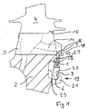
- FIG. 1 is a schematic sectional view of the restraint device, in which a section of a rotor disk 2 is shown in section. At the The outer circumference of the rotor disk 2 is also shown in sections Blade 4 arranged. The blade 4 is in the outer circumference via a blade root 3 the turbine disk 2 formed blade root receptacle 12 and thereby fixed in the radial direction. against displacement in the axial Direction, the blade 4 is secured by a retaining ring 1.
- a flow channel 14 arranged in the area of the blade root 3 is shown in broken lines, which contributes to the improvement of the interstage flow.
- Training a corresponding flow channel 14 is essentially due to the invention Design of the retaining ring 1 possible, the less than one Third, in the present case covering approximately one eighth of the blade root height.
- the outlet opening 16 of the flow channel 14 is free, so that cooling air is out the flow channel 14 in the downstream of the rotor disc 2 Space between the panes can occur.
- the retention and sealing function decoupled from each other.
- the sealing function to avoid leakage from a blade / disc Perceived sealing surface 15.
- the blade / disc sealing surface 15 is as Mating surface between the bottom 26 of the blade platform and the top of the disc posts 25 arranged between the blade root receptacles 12 are formed.
- the closed, circumferential has protruding inwards on its inner circumference Sections 20, which in claws 21 protruding from the rotor disk 2 intervention.
- the claws 21 are made perpendicular to the turbine disk 2 protruding but interrupted in the circumferential direction (cf. 3) rail 6 and the other from a parallel to the tubing disc 2 arranged (of course also not circulating - see again Fig. 3) stop 9 is formed and are therefore at regular intervals on the circumference the rotor disc 2 arranged.
- the rotor disk 2 has below the Blade root receptacle 12 a circumferential recess 23 (viewed in the axial direction) on, which continues at its lower end as (but interrupted) rail 6 is.
- the recess 23 has a machined guide surface 27, which corresponds to a shoulder 22 of the retaining ring 1.
- Radially inwardly projecting sections 20 and the claws 21 act thereby almost like a bayonet catch.
- the retaining ring 1 is shown in detail in FIG. 2.
- the retaining ring 1 has the step-shaped heel already mentioned above 22 on. This forms a guide with the machined surface 27 of the recess 23 for the retaining ring 1 and thereby enables the exact insertion of the outer circumference of the retaining ring 1 arranged raised portions 17 in a Groove or retaining groove 5 of a protruding retaining lug 18 of the blade 4.
- FIG. 2 shows a locking device 8 for fixing the retaining ring 1 in the circumferential direction.
- the locking device 8 is essentially by a cuboid block formed in the on the inner circumference of the retaining ring 1 inserted between the protruding portions 20 recesses is.
- the locking device 8 is against displacement in the axial direction secured by locking wires 10, each through holes 24 in the two Ends of the locking device 8 are passed, as the perspective view can be seen in Figure 6.
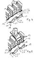
- the basic structure of the retaining ring 1 becomes clearer from the partial view in FIG. 3.
- the retaining ring 1 first becomes perspective, as in FIG. 3 shown, applied to the rotor disc 2.
- the ones from the retaining ring 1 sections 20 projecting radially inwards between two claws 21 the rotor disk 2.
- the blade root receptacles formed on the outer circumference of the rotor disk 2 12 have a fir tree-like toothing 13.
- the retaining ring 1 is now shifted in the circumferential direction, as shown in FIG. that the blade root receptacles 12 are completely released. Slide it that protrude radially inwards on the inner circumference of the retaining ring 1 Sections 20 partially into the claws 21 on the rotor disk 2. Then the blade 4 is inserted into the blade root receptacle 12, as is exemplary for a blade shown in Figure 5.
- the blade 4 has in the area of the blade root 3 a retaining lug 18 with the retaining groove 5 shown in FIGS. 1 and 2 on.
- the outer circumference of the retaining ring 1 arranged raised portions 17 in the corresponding Retaining grooves 5 introduced.
- the retaining lug 18 is also the Outlet opening 16 of the flow channel shown in FIG. 1 is provided or shown.
- the blade 4 is secured and connected to the rotor disk 2 ready for operation, as shown by way of example using a shovel in FIG. 6.
- Figures 7 and 8 show a second embodiment of the present invention.
- the raised sections 17 arranged on the outer circumference of the retaining ring 1 are of sawtooth-like design.
- the sawtooth-like raised sections 17 can be inserted laterally into recesses 28 provided for this purpose on the blade root 3, as indicated schematically in FIG. 7.
- the blade / disk sealing surfaces 15 can also be seen, which take over the function of the contact seal 91 of the prior art shown in FIG. 9.
- FIG. 8 shows a view of the section 17 provided with sawtooth-like raised portions Retaining ring 1.
- the retaining ring 1 is installed in an analog manner Way as described to Figures 1 to 6.
- the retaining ring 1 is radial inwardly projecting sections 20 between two claws 21 each Rotor disk 2.
- the blade root receptacles formed on the outer circumference of the rotor disk 2 12 have a fir tree-like toothing 13.
- the rotor blades, not shown, in the blade root receptacles 12 is the Retaining ring 1 in a manner similar to a bayonet lock in the claws 21 in locked in the axial direction.
- a locking device (not shown) is inserted into the Recesses between the inwardly projecting sections 20 for locking the retaining ring 1 introduced.
Landscapes
- Engineering & Computer Science (AREA)
- Mechanical Engineering (AREA)
- General Engineering & Computer Science (AREA)
- Turbine Rotor Nozzle Sealing (AREA)
Applications Claiming Priority (2)
| Application Number | Priority Date | Filing Date | Title |
|---|---|---|---|
| DE19960896A DE19960896A1 (de) | 1999-12-17 | 1999-12-17 | Rückhaltevorrichtung für Rotorschaufeln einer Axialturbomaschine |
| DE19960896 | 1999-12-17 |
Publications (3)
| Publication Number | Publication Date |
|---|---|
| EP1120545A2 true EP1120545A2 (fr) | 2001-08-01 |
| EP1120545A3 EP1120545A3 (fr) | 2004-01-14 |
| EP1120545B1 EP1120545B1 (fr) | 2006-10-18 |
Family
ID=7933025
Family Applications (1)
| Application Number | Title | Priority Date | Filing Date |
|---|---|---|---|
| EP00118862A Expired - Lifetime EP1120545B1 (fr) | 1999-12-17 | 2000-08-31 | Dispositif de verrouillage des aubes dans une turbine axiale |
Country Status (3)
| Country | Link |
|---|---|
| US (1) | US6488473B1 (fr) |
| EP (1) | EP1120545B1 (fr) |
| DE (2) | DE19960896A1 (fr) |
Cited By (2)
| Publication number | Priority date | Publication date | Assignee | Title |
|---|---|---|---|---|
| EP1096107A3 (fr) * | 1999-10-27 | 2004-05-12 | Rolls-Royce Plc | Dispositif de verrouillage |
| EP1357254A3 (fr) * | 2002-04-16 | 2005-08-31 | United Technologies Corporation | Système de retenue axial et composants dudit système pour un rotor à aubes |
Families Citing this family (22)
| Publication number | Priority date | Publication date | Assignee | Title |
|---|---|---|---|---|
| GB0302116D0 (en) * | 2003-01-30 | 2003-03-05 | Rolls Royce Plc | A rotor |
| GB0413652D0 (en) | 2004-06-18 | 2004-07-21 | Rolls Royce Plc | Gas turbine engine structure |
| US7530791B2 (en) * | 2005-12-22 | 2009-05-12 | Pratt & Whitney Canada Corp. | Turbine blade retaining apparatus |
| JP2007247406A (ja) * | 2006-03-13 | 2007-09-27 | Ihi Corp | ファンブレードの保持構造 |
| FR2900437B1 (fr) * | 2006-04-27 | 2008-07-25 | Snecma Sa | Systeme de retention des aubes dans un rotor |
| FR2928406A1 (fr) * | 2008-03-07 | 2009-09-11 | Snecma Sa | Dispositif de retenue axiale d'aubes montees sur un disque de rotor de turbomachine, disque de rotor et flasque de maintien d'un tel dispositif |
| FR2939832B1 (fr) * | 2008-12-11 | 2011-01-07 | Turbomeca | Roue de turbine equipee d'un dispositif de retenue axiale verrouillant des pales par rapport a un disque. |
| US8814524B2 (en) * | 2008-12-11 | 2014-08-26 | Rolls-Royce Corporation | Wheel formed from a bladed ring and disk |
| FR2939834B1 (fr) * | 2008-12-17 | 2016-02-19 | Turbomeca | Roue de turbine avec systeme de retention axiale des aubes |
| US8905717B2 (en) | 2010-10-06 | 2014-12-09 | General Electric Company | Turbine bucket lockwire rotation prevention |
| US8864471B2 (en) | 2011-08-12 | 2014-10-21 | Hamilton Sundstrand Corporation | Gas turbine rotor with purge blades |
| US9112383B2 (en) | 2011-10-31 | 2015-08-18 | General Electric Company | System and method for Var injection at a distributed power generation source |
| EP2696035A1 (fr) | 2012-08-09 | 2014-02-12 | MTU Aero Engines GmbH | Dispositif de retenue pour aubes mobiles d'une turbomachine et procédé de montage associé |
| US9664056B2 (en) * | 2013-08-23 | 2017-05-30 | General Electric Company | Turbine system and adapter |
| GB201317161D0 (en) * | 2013-09-27 | 2013-11-06 | Rolls Royce Plc | Retainer plate |
| EP2860350A1 (fr) * | 2013-10-10 | 2015-04-15 | Siemens Aktiengesellschaft | Aube de turbine et turbine à gaz |
| EP2860349A1 (fr) * | 2013-10-10 | 2015-04-15 | Siemens Aktiengesellschaft | Aube de turbine et turbine à gaz |
| FR3024491B1 (fr) * | 2014-08-01 | 2018-12-07 | Safran Aircraft Engines | Ensemble rotatif pour turbomachine a dispositif de mise en place d'aubes |
| KR102182102B1 (ko) | 2014-11-27 | 2020-11-23 | 한화에어로스페이스 주식회사 | 터빈 장치 |
| FR3029962B1 (fr) * | 2014-12-11 | 2019-08-23 | Safran Aircraft Engines | Blocage axial des aubes dans une roue de turbomachine |
| EP3564489A1 (fr) * | 2018-05-03 | 2019-11-06 | Siemens Aktiengesellschaft | Rotor à surfaces de contact optimisées au niveau de forces centrifuges |
| EP3581765A1 (fr) * | 2018-06-11 | 2019-12-18 | Siemens Aktiengesellschaft | Rotor pourvu de pales tournantes verrouillées axialement sur le disque de rotor |
Citations (3)
| Publication number | Priority date | Publication date | Assignee | Title |
|---|---|---|---|---|
| US4846628A (en) | 1988-12-23 | 1989-07-11 | United Technologies Corporation | Rotor assembly for a turbomachine |
| EP0463955B1 (fr) | 1990-06-27 | 1994-09-21 | Societe Nationale D'etude Et De Construction De Moteurs D'aviation "Snecma" | Dispositif de fixation d'une couronne de révolution sur un disque de turbomachine |
| EP0761930A1 (fr) | 1995-08-24 | 1997-03-12 | ROLLS-ROYCE plc | Segments d'étanchéité et de rétention pour les aubes d'une turbomachine |
Family Cites Families (14)
| Publication number | Priority date | Publication date | Assignee | Title |
|---|---|---|---|---|
| GB1479332A (en) * | 1974-11-06 | 1977-07-13 | Rolls Royce | Means for retaining blades to a disc or like structure |
| GB2042652B (en) * | 1979-02-21 | 1983-07-20 | Rolls Royce | Joint making packing |
| US4566857A (en) * | 1980-12-19 | 1986-01-28 | United Technologies Corporation | Locking of rotor blades on a rotor disk |
| FR2524932A1 (fr) * | 1982-04-08 | 1983-10-14 | Snecma | Dispositif de retenue axiale de pieds d'aube dans un disque de turbomachine |
| FR2603333B1 (fr) * | 1986-09-03 | 1990-07-20 | Snecma | Rotor de turbomachine comportant un moyen de verrouillage axial et d'etancheite d'aubes montees dans des brochages axiaux du disque et procede de montage |
| GB8705216D0 (en) * | 1987-03-06 | 1987-04-08 | Rolls Royce Plc | Rotor assembly |
| FR2637321B1 (fr) * | 1988-10-05 | 1990-11-30 | Snecma | Rotor de turbomachine muni d'un dispositif de fixation des aubes |
| US4921405A (en) * | 1988-11-10 | 1990-05-01 | Allied-Signal Inc. | Dual structure turbine blade |
| US5112193A (en) * | 1990-09-11 | 1992-05-12 | Pratt & Whitney Canada | Fan blade axial retention device |
| GB2258273B (en) * | 1991-08-02 | 1994-08-10 | Ruston Gas Turbines Ltd | Rotor blade locking arrangement |
| US5256035A (en) * | 1992-06-01 | 1993-10-26 | United Technologies Corporation | Rotor blade retention and sealing construction |
| FR2695433B1 (fr) * | 1992-09-09 | 1994-10-21 | Snecma | Joint annulaire d'étanchéité disposé à une extrémité axiale d'un rotor et recouvrant des brochages d'aubes. |
| FR2710103B1 (fr) * | 1993-09-16 | 1995-10-20 | Snecma | Flasque de rotor de turbomachine et assemblage de ce flasque avec un rotor. |
| GB2317652B (en) * | 1996-09-26 | 2000-05-17 | Rolls Royce Plc | Seal arrangement |
-
1999
- 1999-12-17 DE DE19960896A patent/DE19960896A1/de not_active Withdrawn
-
2000
- 2000-08-31 DE DE50013633T patent/DE50013633D1/de not_active Expired - Lifetime
- 2000-08-31 EP EP00118862A patent/EP1120545B1/fr not_active Expired - Lifetime
- 2000-09-20 US US09/666,145 patent/US6488473B1/en not_active Expired - Lifetime
Patent Citations (3)
| Publication number | Priority date | Publication date | Assignee | Title |
|---|---|---|---|---|
| US4846628A (en) | 1988-12-23 | 1989-07-11 | United Technologies Corporation | Rotor assembly for a turbomachine |
| EP0463955B1 (fr) | 1990-06-27 | 1994-09-21 | Societe Nationale D'etude Et De Construction De Moteurs D'aviation "Snecma" | Dispositif de fixation d'une couronne de révolution sur un disque de turbomachine |
| EP0761930A1 (fr) | 1995-08-24 | 1997-03-12 | ROLLS-ROYCE plc | Segments d'étanchéité et de rétention pour les aubes d'une turbomachine |
Cited By (2)
| Publication number | Priority date | Publication date | Assignee | Title |
|---|---|---|---|---|
| EP1096107A3 (fr) * | 1999-10-27 | 2004-05-12 | Rolls-Royce Plc | Dispositif de verrouillage |
| EP1357254A3 (fr) * | 2002-04-16 | 2005-08-31 | United Technologies Corporation | Système de retenue axial et composants dudit système pour un rotor à aubes |
Also Published As
| Publication number | Publication date |
|---|---|
| US6488473B1 (en) | 2002-12-03 |
| DE50013633D1 (de) | 2006-11-30 |
| EP1120545B1 (fr) | 2006-10-18 |
| EP1120545A3 (fr) | 2004-01-14 |
| DE19960896A1 (de) | 2001-06-28 |
Similar Documents
| Publication | Publication Date | Title |
|---|---|---|
| EP1120545B1 (fr) | Dispositif de verrouillage des aubes dans une turbine axiale | |
| EP2399004B1 (fr) | Section de rotor pour un rotor d'une turbomachine, aube rotorique pour une turbomachine et élément de blocage | |
| DE60202738T2 (de) | Vorrichtung zur Sicherung von Laufschaufeln in einer Nut einer Rotorscheibe | |
| DE3148984C2 (fr) | ||
| DE102010060284B4 (de) | Sicherungs-Abstandshalteranordnung für ein Schaufelblattbefestigungssystem zur Einführung in Umfangsrichtung und Rotoranordnung mit derartiger Sicherungs-Abstandshalteranordnung | |
| DE2854629A1 (de) | Halteeinrichtung fuer turbinenrotorschaufeln | |
| WO1991006387A1 (fr) | Foret helicoidal | |
| DE19828817C2 (de) | Rotor für eine Turbomaschine | |
| DE3148985C2 (de) | Rotorbaugruppe | |
| DE2514050C2 (de) | Verriegelung von am Rotorkörper von Turbomaschinen angebrachten Schaufeln | |
| EP1134359B1 (fr) | Verrou pour aube de turbomachine et sa methode de fabrication | |
| EP1215367A2 (fr) | Dispositif de fixation des aubes de turbomachine | |
| EP3574188B1 (fr) | Procédé permettant de fermer de manière étanche un interstice annulaire dans une turbine ainsi que turbine | |
| DE102004051116A1 (de) | Rotor einer Turbomaschine, insbesondere Gasturbinenrotor | |
| DE102004057025B4 (de) | Verfahren zum Installieren von ortsfesten Schaufeln einer Turbine und Turbinenstruktur mit einem radialen Spannstift | |
| DE2002469A1 (de) | Schaufelsicherung | |
| DE19654471B4 (de) | Rotor einer Strömungsmaschine | |
| DE69525014T2 (de) | Abdeckstück zur Abdichtung des Raums zwischen Rotorstufen | |
| DE967498C (de) | Laufschaufelbefestigung bei Axialstroemungsmaschinen | |
| EP0965729A2 (fr) | Elément de verrouillage pour des aubes de turbine | |
| DE602005001231T2 (de) | Verriegelungsmittel für Gasturbinentriebwerke | |
| EP0712995A1 (fr) | Rotor portant des aubes | |
| DE102009007664A1 (de) | Abdichtvorrichtung an dem Schaufelschaft einer Rotorstufe einer axialen Strömungsmaschine | |
| DE102005003511A1 (de) | Rotor einer Turbomaschine, insbesondere Gasturbinenrotor | |
| DE602005005254T2 (de) | Rotorscheibe einer Turbomaschine |
Legal Events
| Date | Code | Title | Description |
|---|---|---|---|
| PUAI | Public reference made under article 153(3) epc to a published international application that has entered the european phase |
Free format text: ORIGINAL CODE: 0009012 |
|
| AK | Designated contracting states |
Kind code of ref document: A2 Designated state(s): AT BE CH CY DE DK ES FI FR GB GR IE IT LI LU MC NL PT SE |
|
| AX | Request for extension of the european patent |
Free format text: AL;LT;LV;MK;RO;SI |
|
| PUAL | Search report despatched |
Free format text: ORIGINAL CODE: 0009013 |
|
| AK | Designated contracting states |
Kind code of ref document: A3 Designated state(s): AT BE CH CY DE DK ES FI FR GB GR IE IT LI LU MC NL PT SE |
|
| AX | Request for extension of the european patent |
Extension state: AL LT LV MK RO SI |
|
| RIC1 | Information provided on ipc code assigned before grant |
Ipc: 7F 01D 5/30 B Ipc: 7F 01D 11/00 B Ipc: 7F 01D 5/32 A |
|
| 17P | Request for examination filed |
Effective date: 20040512 |
|
| AKX | Designation fees paid |
Designated state(s): DE FR GB |
|
| GRAP | Despatch of communication of intention to grant a patent |
Free format text: ORIGINAL CODE: EPIDOSNIGR1 |
|
| RTI1 | Title (correction) |
Free format text: LOCKING DEVICE FOR ROTORBLADES IN AXIAL TURBINES |
|
| GRAS | Grant fee paid |
Free format text: ORIGINAL CODE: EPIDOSNIGR3 |
|
| RIN1 | Information on inventor provided before grant (corrected) |
Inventor name: MOELLER, TIM Inventor name: BROADHEAD, PETER Inventor name: LEE, STUART, DR. |
|
| GRAA | (expected) grant |
Free format text: ORIGINAL CODE: 0009210 |
|
| AK | Designated contracting states |
Kind code of ref document: B1 Designated state(s): DE FR GB |
|
| REG | Reference to a national code |
Ref country code: GB Ref legal event code: FG4D Free format text: NOT ENGLISH |
|
| GBT | Gb: translation of ep patent filed (gb section 77(6)(a)/1977) |
Effective date: 20061106 |
|
| REF | Corresponds to: |
Ref document number: 50013633 Country of ref document: DE Date of ref document: 20061130 Kind code of ref document: P |
|
| ET | Fr: translation filed | ||
| PLBE | No opposition filed within time limit |
Free format text: ORIGINAL CODE: 0009261 |
|
| STAA | Information on the status of an ep patent application or granted ep patent |
Free format text: STATUS: NO OPPOSITION FILED WITHIN TIME LIMIT |
|
| 26N | No opposition filed |
Effective date: 20070719 |
|
| REG | Reference to a national code |
Ref country code: DE Ref legal event code: R082 Ref document number: 50013633 Country of ref document: DE Representative=s name: HOEFER & PARTNER, DE |
|
| REG | Reference to a national code |
Ref country code: DE Ref legal event code: R082 Ref document number: 50013633 Country of ref document: DE Representative=s name: HOEFER & PARTNER, DE Effective date: 20130402 Ref country code: DE Ref legal event code: R081 Ref document number: 50013633 Country of ref document: DE Owner name: ROLLS-ROYCE DEUTSCHLAND LTD & CO KG, DE Free format text: FORMER OWNER: ROLLS-ROYCE DEUTSCHLAND LTD & CO KG, 15827 BLANKENFELDE, DE Effective date: 20130402 Ref country code: DE Ref legal event code: R082 Ref document number: 50013633 Country of ref document: DE Representative=s name: HOEFER & PARTNER PATENTANWAELTE MBB, DE Effective date: 20130402 |
|
| REG | Reference to a national code |
Ref country code: FR Ref legal event code: PLFP Year of fee payment: 17 |
|
| REG | Reference to a national code |
Ref country code: FR Ref legal event code: PLFP Year of fee payment: 18 |
|
| PGFP | Annual fee paid to national office [announced via postgrant information from national office to epo] |
Ref country code: FR Payment date: 20170825 Year of fee payment: 18 Ref country code: GB Payment date: 20170829 Year of fee payment: 18 Ref country code: DE Payment date: 20170829 Year of fee payment: 18 |
|
| REG | Reference to a national code |
Ref country code: DE Ref legal event code: R082 Ref document number: 50013633 Country of ref document: DE |
|
| REG | Reference to a national code |
Ref country code: DE Ref legal event code: R119 Ref document number: 50013633 Country of ref document: DE |
|
| GBPC | Gb: european patent ceased through non-payment of renewal fee |
Effective date: 20180831 |
|
| PG25 | Lapsed in a contracting state [announced via postgrant information from national office to epo] |
Ref country code: DE Free format text: LAPSE BECAUSE OF NON-PAYMENT OF DUE FEES Effective date: 20190301 |
|
| PG25 | Lapsed in a contracting state [announced via postgrant information from national office to epo] |
Ref country code: FR Free format text: LAPSE BECAUSE OF NON-PAYMENT OF DUE FEES Effective date: 20180831 |
|
| PG25 | Lapsed in a contracting state [announced via postgrant information from national office to epo] |
Ref country code: GB Free format text: LAPSE BECAUSE OF NON-PAYMENT OF DUE FEES Effective date: 20180831 |