EP1120631A1 - Dispositif de navigation - Google Patents
Dispositif de navigation Download PDFInfo
- Publication number
- EP1120631A1 EP1120631A1 EP99926964A EP99926964A EP1120631A1 EP 1120631 A1 EP1120631 A1 EP 1120631A1 EP 99926964 A EP99926964 A EP 99926964A EP 99926964 A EP99926964 A EP 99926964A EP 1120631 A1 EP1120631 A1 EP 1120631A1
- Authority
- EP
- European Patent Office
- Prior art keywords
- tunnel
- vehicle
- mode function
- vehicle speed
- navigation device
- Prior art date
- Legal status (The legal status is an assumption and is not a legal conclusion. Google has not performed a legal analysis and makes no representation as to the accuracy of the status listed.)
- Granted
Links
Images



Classifications
-
- B—PERFORMING OPERATIONS; TRANSPORTING
- B60—VEHICLES IN GENERAL
- B60H—ARRANGEMENTS OF HEATING, COOLING, VENTILATING OR OTHER AIR-TREATING DEVICES SPECIALLY ADAPTED FOR PASSENGER OR GOODS SPACES OF VEHICLES
- B60H1/00—Heating, cooling or ventilating devices
- B60H1/00642—Control systems or circuits; Control members or indication devices for heating, cooling or ventilating devices
- B60H1/00735—Control systems or circuits characterised by their input, i.e. by the detection, measurement or calculation of particular conditions, e.g. signal treatment, dynamic models
- B60H1/00764—Control systems or circuits characterised by their input, i.e. by the detection, measurement or calculation of particular conditions, e.g. signal treatment, dynamic models the input being a vehicle driving condition, e.g. speed
- B60H1/00771—Control systems or circuits characterised by their input, i.e. by the detection, measurement or calculation of particular conditions, e.g. signal treatment, dynamic models the input being a vehicle driving condition, e.g. speed the input being a vehicle position or surrounding, e.g. GPS-based position or tunnel
-
- G—PHYSICS
- G01—MEASURING; TESTING
- G01C—MEASURING DISTANCES, LEVELS OR BEARINGS; SURVEYING; NAVIGATION; GYROSCOPIC INSTRUMENTS; PHOTOGRAMMETRY OR VIDEOGRAMMETRY
- G01C21/00—Navigation; Navigational instruments not provided for in groups G01C1/00 - G01C19/00
- G01C21/26—Navigation; Navigational instruments not provided for in groups G01C1/00 - G01C19/00 specially adapted for navigation in a road network
- G01C21/34—Route searching; Route guidance
- G01C21/36—Input/output arrangements for on-board computers
- G01C21/3626—Details of the output of route guidance instructions
- G01C21/3644—Landmark guidance, e.g. using POIs or conspicuous other objects
-
- G—PHYSICS
- G01—MEASURING; TESTING
- G01C—MEASURING DISTANCES, LEVELS OR BEARINGS; SURVEYING; NAVIGATION; GYROSCOPIC INSTRUMENTS; PHOTOGRAMMETRY OR VIDEOGRAMMETRY
- G01C21/00—Navigation; Navigational instruments not provided for in groups G01C1/00 - G01C19/00
- G01C21/26—Navigation; Navigational instruments not provided for in groups G01C1/00 - G01C19/00 specially adapted for navigation in a road network
- G01C21/34—Route searching; Route guidance
- G01C21/36—Input/output arrangements for on-board computers
- G01C21/3697—Output of additional, non-guidance related information, e.g. low fuel level
Definitions
- the present invention relates to a navigation device which indicates the characteristics of a tunnel on the display before entering the tunnel when a vehicle's approach to the tunnel is detected using a navigation function.
- the safety and comfort of the driver are maintained by displaying a precaution with respect to conditions resulting from entering the tunnel.
- Fig. 1 shows a conventional navigation device as disclosed for example in JP-A-10-100815.
- the navigation device is adapted to detect a vehicle's approach to a tunnel and activate various on-vehicle devices in a tunnel mode function on the basis of the detected signal.
- reference numeral 1 denotes a navigation computer means with a database (not shown). Map data is stored in the database, the map data includes data on the accurate position of tunnels as well as data on a road network, which can be travelled on by the vehicle, and the road network surroundings.
- 2 is a GPS antenna
- 3 is a vehicle position detection means
- 4 is a control means which controls the operation of the on-vehicle devices based on the output signal from the navigation computer means 1.
- 5 is a window operation means provided with a motor
- 6 is a headlight control means
- 7 is a sunroof operation means
- 8 is an air conditioner switching means which switches an air circulation mode
- 9 is a manual tunnel switch for controlling the activation of each means manually based on the display command from the control means 4 with respect to the tunnel mode function.
- the navigation computer means 1 determines a vehicle position continuously on a road network on the basis of a GPS satellite signal from a GPS antenna and an output signal of the vehicle position detection means 3. From the continuously obtained position, the navigation computer means 1 confirms whether the vehicle is currently traveling inside or outside a tunnel on a searched route. If the vehicle is currently inside a tunnel, the navigation computer means 1 confirms whether the vehicle has just entered the tunnel or has just finished travelling through the tunnel.
- an appropriate message signal is transmitted to the control means 4.
- the control means 4 selects on-vehicle devices to be activated in a tunnel mode function in response to the transmitted signal and automatically activates the tunnel mode function.
- a display suggesting operation of the manual tunnel switch 9 is performed.
- a driver operates the manual tunnel switch 9 based on this display and various types of on-vehicle equipment are activated in the tunnel mode function.
- such a tunnel mode function includes,
- the conventional navigation device is constructed as the above, on-vehicle devices are activated in a tunnel mode function or are placed in an operable state for the tunnel mode function if it is confirmed that a vehicle will enter a tunnel on a currently traveled searched route.
- various on-vehicle devices are switched intermittently between the tunnel mode and the other modes.
- the problem has arisen that even when the tunnel mode function is activated, since information such as the length of the tunnel, lane number, presence of traffic signals in the tunnel is not known, the driver has to enter the tunnel in a tense, uneasy state.
- the inside of the tunnel is sloping and the road extends in a descending slope towards the tunnel exit, vehicle speed will naturally increase.
- the road curves at the tunnel exit the possibility exists of dangerous conditions.
- the present invention is proposed to solve the above problems and has the object of providing a navigation device which performs a precautionary function by informing characteristics of a tunnel to a driver before entering the tunnel when a vehicle encounters a tunnel.
- characteristics include for example, the name of the tunnel, the shape of the tunnel (length, height, width, presence of curves), the lane number, and the presence of traffic lights or the like.
- the navigation device comprises: a vehicle position detection means for detecting a vehicle position; a vehicle speed detection means for detecting a vehicle speed; a determination means provided with a database which records data on a currently traveled route network, data on the surroundings thereof, and characteristic data relating to tunnels on the route network, the determination means determining whether or not to activate a tunnel mode function on the basis of the characteristic data relating to the tunnel read from the database, the vehicle speed detected by the vehicle speed detection means and the vehicle position detected by the vehicle position detection means; and a control means for displaying characteristics of the tunnel to be travelled through on a display means based on a command signal from the determination means indicative of activation of the tunnel mode function and for activating each on-vehicle device in the tunnel mode function or suggesting activation of the tunnel mode function.
- the navigation device of the present invention is adapted to determine whether to activate a tunnel mode function in consideration of the vehicle speed and the displayed information about the tunnel, and to automatically activate various on-vehicle devices in the tunnel mode function or display the suggestion to activate the tunnel mode function in order to instruct a driver to operate the manual tunnel switch.
- the navigation device of the present invention may be adapted to display a longitudinal sectional view of the tunnel through which the vehicle will travel on a display section of the navigation means when the tunnel mode function is activated.
- the navigation device of the present invention may be adapted to display characteristic information relating to the tunnel through which the vehicle will travel on a display section of the navigation means.
- the navigation device of the present invention is adapted to calculate a distance to a tunnel based on a vehicle speed detected by a vehicle speed detection means when the vehicle lies within a link area in map data on which the tunnel exists.
- a distance to a tunnel based on a vehicle speed detected by a vehicle speed detection means when the vehicle lies within a link area in map data on which the tunnel exists.
- the navigation device of the present invention may be adapted to determine whether or not to guide a tunnel based on the tunnel length and an average vehicle speed before entering the tunnel.
- Fig. 2 is a block diagram schematically showing the configuration of a navigation device according to a first embodiment of the present invention.
- reference numeral 11 denotes a GPS antenna
- 12 is an automatic vehicle position detection means which detects a vehicle position based on a received signal from the GPS antenna 11.
- 13 is a determination means which has a database which stores data on a currently traveled route network, data on the surroundings thereof, and characteristic data relating to tunnels on a route network. The determination means 13 determines whether or not to activate a tunnel mode function based on the characteristic data relating to the tunnel read from the database, the vehicle speed detected by the vehicle speed detection means 14 and the vehicle position detected by the vehicle position detection means 12.
- the determination of when to display the tunnel through which the vehicle will travel is performed based on the following procedure. For example, when a tunnel exists on a travel route to be displayed on a map and the vehicle enters the link area on which the tunnel exists, a distance to the tunnel is calculated in consideration of the vehicle speed detected by the vehicle speed detection means. Then, if the distance is not more than a pre-set fixed value, characteristics of the tunnel and a longitudinal section of the tunnel 22 in the direction of travel as shown in Fig. 4 are displayed.
- the tunnel characteristics include, for example, the name of the tunnel, the shape of the tunnel (height, width, length, presence of curves), the lane number in the tunnel, the presence of a plurality of tunnels in a short distance (hereafter this is termed "continuous tunnel", that is to say, when there is a single short tunnel, the possibility exists that it is not necessary to switch to a tunnel mode function and when a plurality of tunnels continues, it will be often the case that the device should be switched to the tunnel mode function), the presence of traffic lights in the tunnel or the like.
- sudden information related to traffic congestion and the presence of traffic restrictions is displayed on the display means 16.
- the position of fire extinguishing valves 22a, the position of emergency exits 22b as well as the maximum angle of slope, the length and name of the tunnel may be added as shown in Fig. 5.
- the tunnel may be displayed in a deformation 3-D presentation.
- 17 denotes a window operation means which opens and closes a door window
- 18 is a headlight control means which operates the beam of the headlights
- 19 is a sunroof operation means which opens and closes the sunroof
- 20 is an air conditioner switching means which switches an air conditioner mode
- 21 is a manual tunnel switch which activates each means manually in the tunnel mode function when the activation of the tunnel mode function is displayed by the determination of the central control means.
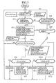
- Fig. 3 is a flowchart showing the operation of the navigation device.
- the vehicle position detection means 12 receives a GPS signal through the GPS antenna 11, reads data on a route network from a database and specifies a vehicle position on the route network (step ST1).
- the determination means 13 determines whether a tunnel is approaching based on a signal indicative of the vehicle position specified as above and the vehicle speed detected by the vehicle detection means 14 (step ST2). If the answer is "Yes", the control means 15 receives a determination signal from the determination means 13 and displays characteristics of the tunnel on the display means 16 (step ST3). Then, it is determined whether it is necessary to switch the various on-vehicle devices to the tunnel mode function in consideration of current average vehicle speed, tunnel length and the like (step ST4).
- control means 15 effects the following operations.
- the switching may be performed manually by operation of the manual tunnel switch 21 based on a command display indicating that switching of the various on-vehicle devices to the tunnel mode function should be performed.
- step ST5 it is determined whether the state of the vehicle is in the tunnel mode function. If the result of the determination is "Yes”, no action is taken (step ST6). If the answer is "No”, the tunnel mode function is automatically activated or suggestion to activate the tunnel mode function is given by voice command or display (step ST7).
- a method of activating the tunnel mode function there are some methods such as an automatic activation method (in view of safety considerations), manual activation method by operation of the manual tunnel switch 21 provided in the vehicle, and a method of suggesting activation of the tunnel mode function to the driver by audio-visual instruction.
- step ST2 determines whether or not the vehicle will exit the tunnel soon.
- step ST8 determines whether or not the vehicle will exit the tunnel soon.
- step ST9 determines whether or not a continuous tunnel exists. If the answer is "Yes”, the routine returns to the step ST3 and the tunnel characteristics are displayed. If the answer is "No”, the routine performs the opposite operation to (1) to (5) above. That is to say:
- step ST10 it is determined whether the vehicle is in the tunnel mode function. If the result of the determination is "No”, no action is taken (step ST11). If the result of the determination is "Yes”, the tunnel mode function is automatically deactivated or suggestion to deactivate the tunnel mode function is given by voice command or display (step ST12). Deactivation of the tunnel mode function is effected in the same manner as activation of the tunnel mode function as discussed above, the on-vehicle devices are returned to the state immediately before activating the tunnel mode function.
- suggestion to the driver may be given by voice commands.
- Unnecessary tunnel guiding can be prevented by performing a determination as to whether the tunnel mode function should be activated, based on the distance to the tunnel and the vehicle speed.
- the tunnel mode function should be activated.
- tunnel characteristics such as, for example, the name of the tunnel, the shape of the tunnel (height, width, length, presence of curves), the lane number in the tunnel, the presence of a plurality of tunnels in a short distance (hereafter this is termed "continuous tunnel", that is to say, when there is a single short tunnel, the possibility exists that it is not necessary to switch to the tunnel mode function, but when a plurality of tunnels continues, it will be often the case that the device should be switched to the tunnel mode function), the presence of traffic lights in the tunnel or the like are displayed.
- a longitudinal cross section of the tunnel 22 in the direction of travel is also displayed.
- the navigation device is adapted to indicate tunnel conditions in a tunnel which will be travelled through to the driver beforehand by indication of the tunnel characteristics when the vehicle approaches the tunnel on a travel route is approaching, and thus to increase driving safety and comfort due to the extra time allowed for driving.
Landscapes
- Engineering & Computer Science (AREA)
- Radar, Positioning & Navigation (AREA)
- Remote Sensing (AREA)
- Automation & Control Theory (AREA)
- Physics & Mathematics (AREA)
- General Physics & Mathematics (AREA)
- Thermal Sciences (AREA)
- Mechanical Engineering (AREA)
- Navigation (AREA)
- Traffic Control Systems (AREA)
Applications Claiming Priority (1)
| Application Number | Priority Date | Filing Date | Title |
|---|---|---|---|
| PCT/JP1999/003655 WO2001002805A1 (fr) | 1999-07-06 | 1999-07-06 | Dispositif de navigation |
Publications (3)
| Publication Number | Publication Date |
|---|---|
| EP1120631A1 true EP1120631A1 (fr) | 2001-08-01 |
| EP1120631A4 EP1120631A4 (fr) | 2002-08-28 |
| EP1120631B1 EP1120631B1 (fr) | 2008-12-24 |
Family
ID=14236170
Family Applications (1)
| Application Number | Title | Priority Date | Filing Date |
|---|---|---|---|
| EP99926964A Expired - Lifetime EP1120631B1 (fr) | 1999-07-06 | 1999-07-06 | Dispositif de navigation |
Country Status (4)
| Country | Link |
|---|---|
| US (1) | US6411894B2 (fr) |
| EP (1) | EP1120631B1 (fr) |
| DE (1) | DE69940160D1 (fr) |
| WO (1) | WO2001002805A1 (fr) |
Cited By (3)
| Publication number | Priority date | Publication date | Assignee | Title |
|---|---|---|---|---|
| EP1302746A1 (fr) * | 2001-10-15 | 2003-04-16 | Ford Global Technologies, Inc. | Système et procédé pour la commande d'un système de confort véhiculaire |
| US6853908B2 (en) | 2001-10-15 | 2005-02-08 | Ford Motor Company | System and method for controlling an object detection system of a vehicle |
| EP2178062A2 (fr) * | 2008-10-14 | 2010-04-21 | LG Electronics Inc. | Terminal télématique et procédé de contrôle de véhicule l'utilisant |
Families Citing this family (27)
| Publication number | Priority date | Publication date | Assignee | Title |
|---|---|---|---|---|
| JP3659144B2 (ja) | 2000-08-25 | 2005-06-15 | トヨタ自動車株式会社 | 入力画面の制御装置 |
| US20040225434A1 (en) * | 2003-05-07 | 2004-11-11 | Gotfried Bradley L. | Vehicle navigation and safety systems |
| DE10320744B3 (de) * | 2003-05-09 | 2004-12-09 | Daimlerchrysler Ag | Vorrichtung und Verfahren zur Klimaregelung |
| US7302339B2 (en) * | 2003-07-21 | 2007-11-27 | Justin Gray | Hazard countermeasure system and method for vehicles |
| US20060271246A1 (en) * | 2005-05-27 | 2006-11-30 | Richard Bell | Systems and methods for remote vehicle management |
| JP2007033299A (ja) * | 2005-07-28 | 2007-02-08 | Alpine Electronics Inc | 車載用ナビゲーション装置 |
| JP4923868B2 (ja) * | 2006-08-30 | 2012-04-25 | 株式会社デンソー | 自動制御装置 |
| AU2007343335A1 (en) * | 2007-01-10 | 2008-07-17 | Tomtom International B.V. | Method of indicating traffic delays, computer program and navigation system therefor |
| DE102007020434B4 (de) * | 2007-04-19 | 2011-01-05 | Navigon Ag | Verfahren zum Betrieb einer Einrichtung |
| DE102008006445A1 (de) * | 2008-01-28 | 2009-08-20 | Navigon Ag | Verfahren zum Betrieb eines Navigationsgeräts |
| US8957769B2 (en) * | 2009-01-30 | 2015-02-17 | Panasonic Automotive Systems Company Of America, Division Of Panasonic Corporation Of North America | Method for driver personalization based on tunnel detection for a single-tuner system |
| JP4738550B2 (ja) * | 2009-02-16 | 2011-08-03 | 三菱電機株式会社 | 地図情報処理装置 |
| WO2010095193A1 (fr) * | 2009-02-17 | 2010-08-26 | 三菱電機株式会社 | Dispositif de traitement d'informations cartographiques |
| JPWO2010095197A1 (ja) * | 2009-02-18 | 2012-08-16 | 三菱電機株式会社 | 地図情報処理装置 |
| JP2011057148A (ja) * | 2009-09-11 | 2011-03-24 | Yupiteru Corp | 車載用電子機器及びプログラム |
| JP5372802B2 (ja) * | 2010-02-24 | 2013-12-18 | クラリオン株式会社 | トンネル内位置推定機能付きナビゲーション装置 |
| US8909468B2 (en) * | 2011-06-07 | 2014-12-09 | General Motors Llc | Route portals |
| JP6151019B2 (ja) * | 2012-12-28 | 2017-06-21 | ラピスセミコンダクタ株式会社 | 半導体装置、電子機器、及び電源制御方法 |
| JP6127775B2 (ja) * | 2013-06-26 | 2017-05-17 | アイシン・エィ・ダブリュ株式会社 | ナビゲーションシステム、ナビゲーション方法、及びナビゲーションプログラム |
| JP2015230573A (ja) * | 2014-06-05 | 2015-12-21 | アルパイン株式会社 | 車両運転支援装置、方法およびプログラム |
| DE202014009304U1 (de) * | 2014-11-22 | 2016-02-25 | GM Global Technology Operations LLC (n. d. Ges. d. Staates Delaware) | Fahrerassistenzsystem |
| JP7346981B2 (ja) * | 2019-07-30 | 2023-09-20 | マツダ株式会社 | 車両制御システム |
| US11602974B2 (en) | 2019-08-29 | 2023-03-14 | Here Global B.V. | System and method for generating map data associated with road objects |
| DE102020102286A1 (de) | 2020-01-30 | 2021-08-05 | Bayerische Motoren Werke Aktiengesellschaft | Verfahren und Fahrzeug zum Ansteuern eines elektrisch betätigbaren Fahrzeugfensters |
| US11610332B2 (en) * | 2020-12-22 | 2023-03-21 | Here Global B.V. | Method and apparatus for detecting a start location and end location of a bridge |
| CN113460125B (zh) * | 2021-05-26 | 2022-08-23 | 万朝栋 | 盾构施工水平运输中电瓶车组安全行驶自动控制系统 |
| CN116901874A (zh) * | 2023-07-13 | 2023-10-20 | 重庆赛力斯新能源汽车设计院有限公司 | 智能座舱模式控制方法、设备及介质 |
Family Cites Families (12)
| Publication number | Priority date | Publication date | Assignee | Title |
|---|---|---|---|---|
| JPH06317650A (ja) * | 1993-04-30 | 1994-11-15 | Matsushita Electric Ind Co Ltd | Gpsナビゲーション装置 |
| JPH06317654A (ja) * | 1993-05-10 | 1994-11-15 | Mitsubishi Electric Corp | 電波受信装置 |
| JP3136907B2 (ja) * | 1994-07-22 | 2001-02-19 | 住友電気工業株式会社 | 経路案内装置 |
| KR100256620B1 (ko) * | 1995-10-30 | 2000-05-15 | 모리 하루오 | 네비게이션장치 |
| JPH09142232A (ja) * | 1995-11-24 | 1997-06-03 | Toshiki Furuya | 自動車のトンネルモードシステム |
| DE19619643C1 (de) * | 1996-05-15 | 1997-07-17 | Daimler Benz Ag | Fahrzeug mit Navigationseinrichtung |
| JPH10815A (ja) | 1996-06-18 | 1998-01-06 | Canon Inc | プリント方法およびプリント装置 |
| JPH10175478A (ja) | 1996-12-18 | 1998-06-30 | Koito Mfg Co Ltd | 車輌用灯具装置 |
| US6199001B1 (en) * | 1996-12-19 | 2001-03-06 | Toyota Jidosha Kabushiki Kaisha | Control system for controlling the behavior of a vehicle based on accurately detected route information |
| JPH10236246A (ja) * | 1997-02-27 | 1998-09-08 | Sony Corp | 制御方法、ナビゲーション装置及び自動車 |
| JPH10247299A (ja) * | 1997-03-04 | 1998-09-14 | Fujitsu Ten Ltd | 車両の走行制御装置及び車両の走行制御システム |
| JPH10313484A (ja) * | 1997-05-10 | 1998-11-24 | Daihatsu Motor Co Ltd | ハンズフリー装置の制御方法 |
-
1999
- 1999-07-06 EP EP99926964A patent/EP1120631B1/fr not_active Expired - Lifetime
- 1999-07-06 DE DE69940160T patent/DE69940160D1/de not_active Expired - Lifetime
- 1999-07-06 WO PCT/JP1999/003655 patent/WO2001002805A1/fr not_active Ceased
-
2001
- 2001-02-21 US US09/788,576 patent/US6411894B2/en not_active Expired - Lifetime
Cited By (4)
| Publication number | Priority date | Publication date | Assignee | Title |
|---|---|---|---|---|
| EP1302746A1 (fr) * | 2001-10-15 | 2003-04-16 | Ford Global Technologies, Inc. | Système et procédé pour la commande d'un système de confort véhiculaire |
| US6853908B2 (en) | 2001-10-15 | 2005-02-08 | Ford Motor Company | System and method for controlling an object detection system of a vehicle |
| EP2178062A2 (fr) * | 2008-10-14 | 2010-04-21 | LG Electronics Inc. | Terminal télématique et procédé de contrôle de véhicule l'utilisant |
| US8825369B2 (en) | 2008-10-14 | 2014-09-02 | Lg Electronics Inc. | Telematics terminal and method for controlling vehicle using the same |
Also Published As
| Publication number | Publication date |
|---|---|
| WO2001002805A1 (fr) | 2001-01-11 |
| EP1120631B1 (fr) | 2008-12-24 |
| US20010007967A1 (en) | 2001-07-12 |
| EP1120631A4 (fr) | 2002-08-28 |
| DE69940160D1 (de) | 2009-02-05 |
| US6411894B2 (en) | 2002-06-25 |
Similar Documents
| Publication | Publication Date | Title |
|---|---|---|
| EP1120631B1 (fr) | Dispositif de navigation | |
| US6108602A (en) | Vehicle with navigation device | |
| JP6744528B2 (ja) | 車両制御装置 | |
| US5270708A (en) | Accident information providing system for automotive vehicle | |
| US7783426B2 (en) | Driving support system | |
| US8718858B2 (en) | GPS navigation system | |
| EP1043193A1 (fr) | Support de commande automatique pour accessoire de voiture | |
| JP4639720B2 (ja) | 車両用情報提供システム及びそのセンタ | |
| JP2002024992A (ja) | 車両の交通信号灯連動速度制御システム | |
| CN105644420A (zh) | 一种自动控制车灯的方法、装置及导航设备 | |
| JP3644149B2 (ja) | 車間距離制御型定速走行装置 | |
| US10981506B2 (en) | Display system, vehicle control apparatus, display control method, and storage medium for storing program | |
| US11345288B2 (en) | Display system, vehicle control apparatus, display control method, and storage medium for storing program | |
| KR20180047656A (ko) | 사각 지대 경고 장치, 그를 가지는 차량 및 그 제어 방법 | |
| US20060229793A1 (en) | Vehicular travel control system | |
| US20070158125A1 (en) | Driver assistance system having a function blocking device | |
| CN114867650A (zh) | 车辆的行驶控制方法及行驶控制装置 | |
| US11052822B2 (en) | Vehicle control apparatus, control method, and storage medium for storing program | |
| JP6892666B1 (ja) | 自動運転車 | |
| JPH10320700A (ja) | 車両制御装置 | |
| JP3726326B2 (ja) | 車両用パワーウィンド装置 | |
| JP3890598B2 (ja) | 車両用情報提供装置、車両用情報提供方法及び車両用情報提供プログラム | |
| JP4258486B2 (ja) | 車両用運転者支援装置 | |
| JPH06251286A (ja) | 交通信号装置及び交通信号システム | |
| JPWO2001002805A1 (ja) | ナビゲーション装置 |
Legal Events
| Date | Code | Title | Description |
|---|---|---|---|
| PUAI | Public reference made under article 153(3) epc to a published international application that has entered the european phase |
Free format text: ORIGINAL CODE: 0009012 |
|
| 17P | Request for examination filed |
Effective date: 20010222 |
|
| AK | Designated contracting states |
Kind code of ref document: A1 Designated state(s): AT BE CH CY DE DK ES FI FR GB GR IE IT LI LU MC NL PT SE |
|
| A4 | Supplementary search report drawn up and despatched |
Effective date: 20020717 |
|
| AK | Designated contracting states |
Kind code of ref document: A4 Designated state(s): AT BE CH CY DE DK ES FI FR GB GR IE IT LI LU MC NL PT SE |
|
| RBV | Designated contracting states (corrected) |
Designated state(s): DE |
|
| RAP1 | Party data changed (applicant data changed or rights of an application transferred) |
Owner name: MITSUBISHI DENKI KABUSHIKI KAISHA |
|
| 17Q | First examination report despatched |
Effective date: 20070917 |
|
| GRAP | Despatch of communication of intention to grant a patent |
Free format text: ORIGINAL CODE: EPIDOSNIGR1 |
|
| GRAS | Grant fee paid |
Free format text: ORIGINAL CODE: EPIDOSNIGR3 |
|
| GRAA | (expected) grant |
Free format text: ORIGINAL CODE: 0009210 |
|
| AK | Designated contracting states |
Kind code of ref document: B1 Designated state(s): DE |
|
| REF | Corresponds to: |
Ref document number: 69940160 Country of ref document: DE Date of ref document: 20090205 Kind code of ref document: P |
|
| PLBE | No opposition filed within time limit |
Free format text: ORIGINAL CODE: 0009261 |
|
| STAA | Information on the status of an ep patent application or granted ep patent |
Free format text: STATUS: NO OPPOSITION FILED WITHIN TIME LIMIT |
|
| 26N | No opposition filed |
Effective date: 20090925 |
|
| REG | Reference to a national code |
Ref country code: DE Ref legal event code: R084 Ref document number: 69940160 Country of ref document: DE |
|
| PGFP | Annual fee paid to national office [announced via postgrant information from national office to epo] |
Ref country code: DE Payment date: 20180626 Year of fee payment: 20 |
|
| REG | Reference to a national code |
Ref country code: DE Ref legal event code: R071 Ref document number: 69940160 Country of ref document: DE |