EP1120801B1 - Méthode pour surveiller l' usure des contacts d' un interrupteur à gradins - Google Patents
Méthode pour surveiller l' usure des contacts d' un interrupteur à gradins Download PDFInfo
- Publication number
- EP1120801B1 EP1120801B1 EP00127394A EP00127394A EP1120801B1 EP 1120801 B1 EP1120801 B1 EP 1120801B1 EP 00127394 A EP00127394 A EP 00127394A EP 00127394 A EP00127394 A EP 00127394A EP 1120801 B1 EP1120801 B1 EP 1120801B1
- Authority
- EP
- European Patent Office
- Prior art keywords
- contact
- burning
- contacts
- switching
- resistance
- Prior art date
- Legal status (The legal status is an assumption and is not a legal conclusion. Google has not performed a legal analysis and makes no representation as to the accuracy of the status listed.)
- Expired - Lifetime
Links
Images

Classifications
-
- H—ELECTRICITY
- H01—ELECTRIC ELEMENTS
- H01H—ELECTRIC SWITCHES; RELAYS; SELECTORS; EMERGENCY PROTECTIVE DEVICES
- H01H1/00—Contacts
- H01H1/0015—Means for testing or for inspecting contacts, e.g. wear indicator
-
- H—ELECTRICITY
- H01—ELECTRIC ELEMENTS
- H01H—ELECTRIC SWITCHES; RELAYS; SELECTORS; EMERGENCY PROTECTIVE DEVICES
- H01H9/00—Details of switching devices, not covered by groups H01H1/00 - H01H7/00
- H01H9/0005—Tap change devices
- H01H2009/0061—Monitoring tap change switching devices
Definitions
- the invention relates to a method for monitoring the contact erosion in tap changers, especially the Maisabbrandes of arc-switching contacts, in which these contacts are designed as mechanical switching contacts.
- Tap changers have been in use worldwide for many years for uninterrupted switching between different winding taps of step transformers in large numbers.
- Such tap changer usually consist of a selector for powerless selection of the respective winding tap of the tapped transformer to be switched to, and a diverter switch for the actual switching from the previous to the new, preselected winding tap.
- the diverter switch usually has switching contacts and resistance contacts. The switch contacts are used for direct connection of the respective winding tap with the load dissipation, the resistor contacts for short-term wiring, d. H. Bridging by means of one or more switching resistors.
- diverter switch with thyristors or vacuum switching cells have become known as switching elements, nevertheless, the vast majority of all in-use diverter switch today and probably in the near future still mechanical contacts.
- the switching and resistance contacts such tap changer usually consist of an arc-resistant copper-tungsten alloy. When switching these contacts are regularly arcs that melt or burn small amounts of the contact material and thus lead to a contact erosion.
- the contact erosion of switching and resistance contacts is thus an important criterion for assessing the state of a tap changer and for predicting necessary inspections. All switch-disconnector systems of tap-changers are somewhat dependent on the breakdown of the switching and resistance contacts in terms of their kinematics. If the contacts burn to different extents, the switching and overlapping times of the individual switching steps within the sequence can change during a load changeover in such a way that safe functioning is no longer guaranteed.
- the inspection instructions for tap-changers usually specify the permissible burn-up differences or burn-up limits. If these limits are exceeded, the contacts must either be replaced by new ones or switching and resistance contacts must be interchanged. If a contact is completely burned down, it must be replaced anyway.
- a method for monitoring a diverter switch for a tap changer is also known, occurring during the load switching arcs are recorded in time and by comparing the times between the individual arcs and possibly an additional comparison of the length of the individual arcs each setpoint values, which are stored non-volatile as characteristic variables of the respective tap changer, a function monitoring takes place.
- this method it is possible to detect indirectly by comparing the actual times between the individual arcs with the corresponding setpoints if the life of contacts has been exceeded, ie. H. whose contact erosion has progressed beyond the permissible level. A direct detection and monitoring of contact erosion is not possible.
- DE-OS 27 27 378 a device for controlling the operability of switching devices is generally known, wherein the burn-off takes place here from load current measurements by means of a current transformer. For the special conditions on tap changers this device is not suitable.
- the object of the invention is to provide a method for monitoring the contact erosion in tap changers, which allows reliable and simple as possible and yet exactly the burning of the contacts without requiring visual inspection or required measurements on each contact and corresponding to deviations from a predetermined amount addition Error messages generated.
- the contact erosion of each contact is determined on the basis of a burnup rate A.
- the individual process steps can be carried out in a computer in which the characteristic parameters of the respective tap changer type whose contacts the contact erosion is to be monitored in advance, as well as Abbrandgrenzhong, when exceeding a warning or other message to be generated, are not stored volatile.
- the contact erosion of the respective switching or resistance contact in volume units of the burnable contact material is determined on the basis of a specific burn rate A.
- This burn rate A with the physical unit mm 3 / circuit, ie volume unit / circuit, is a material and current-dependent characteristic.
- J is the current to be disconnected from the contact of the tap changer to be monitored. It results arithmetically in a known manner from the current load current of the transformer which is measured, the current step voltage between two adjacent winding taps, between which is switched, and the respective embodiment of the tap changer.
- the variables a and b are step-switch-specific parameters, which are not stored in advance - as already explained above - not volatile.
- the factor a is in the range of 10 -5 ... 10 -2 .
- a is preferably 8.5 ⁇ 10 -5 .
- the value for b is in the range of 0.8 ... 2.2.
- b is preferably 1.16.
- the described determination of the burn rate A is surrounded by a tolerance band, which must be taken into account for reliable statements.
- a safety margin is therefore no longer flat rate, but determined iteratively becomes.
- the actual contact erosion is measured according to a representative number of contacts. This can happen, for example, in the context of an already required routine inspection.
- the actual volume burnup for each contact is determined from the measured values and compared with the volume burnup determined according to the invention.
- the computationally determined burning rate A is integrated into a method for monitoring the contact erosion.
- the method according to the invention as a whole includes both the determination of the burn rate A and the subsequent determination of the cumulative contact burnup at the respective switching contact, as well as the subsequent generation of situation-related warning or other messages.
- the particular advantage of the method according to the invention lies in the fact that a monitoring possibility of contact erosion of the contacts in the tap changer results in a simple manner, without these contacts themselves having to be accessible for visual inspections, measurements on them or in any other way.
- a further advantage of the invention is that the method according to the invention can be readily implemented in a complex tap-changer and / or transformer monitoring system.
- an input and non-volatile storage of specific tap changer parameters or characteristic data, the respective permissible burnup limit values of the individual contacts and the rated step voltages of each possible circuit, ie operating position of the tap changer takes place.
- an initialization ie the adaptation to the respective tap changer whose contacts are to be monitored.
- An index n is set to zero; the system is ready for use.
- the current step switch position is determined by a position reporting device. If the step switch is now actuated by a switching pulse, a corresponding motor drive moves the tap changer in the direction "higher” or “lower” depending on the direction of rotation. In this and each further operation, the index n is increased by 1.
- the load current J L is measured.
- the corresponding nominal step voltage for the current circuit is read from the non-volatile memory. At the same time it is detected in which direction the circuit was made, and it will both the new Step switch position as well as the respective switching off diverter switch side whose contacts are each switching arc determined.
- ParSek means the number of parallel sectors of the diverter switch, ie, the parallel circuits of individual switch contacts, U S is the respective rated step voltage, and S res is the resulting current division.
- R ü is the size of the switching resistance.
- the burn rates are calculated.
- a and b are the specific factors already explained, s is the safety margin also explained, which is set out here on a flat-rate basis.
- the cumulative Volumenabbrand is determined, ie it is added for switching and resistance contact at each circuit in this circuit computationally determined burn to Automatabbrand, which has resulted from all previous circuits, and stored as a new Volumenabbrand.
- variable n designates the already explained index, which is increased by 1 each time the tap changer is actuated. Subsequently, the burnup in mm contact thickness is calculated from this cumulative volume burnup in mm 3 .
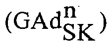
- GAd SK n GA SK n F ⁇ k
- GAd WK n GA WK n F ⁇ k
- F is the respective contact surface of the corresponding contact
- k is a switch-specific correction factor.
- the burnup values calculated in this way thus represent the total, cumulative burnup of the respective contact in mm, d. H. the deviation from the contact thickness when new.
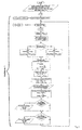
- FIG. 2 shows a correspondingly further developed further method according to the invention.
- further method steps are added to the method already explained with reference to FIG. 1, which make the entire method adaptive. So far it has been described that the contact erosion is subject to certain fluctuations, which is taken into account by the security surcharge s flat rate. If now the accuracy of the burn-up calculation is to be increased, this can be done by adjusting the burn-up rate according to these further method steps. For this purpose, after a representative number of switches of the tap changer, z. B. after 10,000 circuits per contact, the actual contact erosion, usually in mm contact thickness measured. This can be done as part of a routine inspection.
- the volume burnup for each contact is determined from the measured values and compared with the respective calculated volume burnup of this contact according to the method according to the invention.
- the index i indicates the number of inspections carried out, ie. H. Measurements of the actual volume burnup.
Landscapes
- Keying Circuit Devices (AREA)
- Testing Electric Properties And Detecting Electric Faults (AREA)
- Housings And Mounting Of Transformers (AREA)
- Investigating Or Analyzing Materials By The Use Of Electric Means (AREA)
- Measurement Of Length, Angles, Or The Like Using Electric Or Magnetic Means (AREA)
- Water Treatment By Sorption (AREA)
- Treatment Of Water By Oxidation Or Reduction (AREA)
- Measurement Of Resistance Or Impedance (AREA)
- Protection Of Transformers (AREA)
Claims (3)
- Procédé de surveillance de l'usure de contact dans un commutateur de prises comportant des contacts de commutation et des contacts d'usure,
caractérisé en ce que- on enregistre de manière permanente les valeurs de la tension de gradin, nominale respective (US), les valeurs limites de l'usure autorisée des contacts de commutation et des contacts de résistance ainsi que des grandeurs caractéristiques (a, b et k), spécifiques à ce commutateur de prises,- on détermine la position actuelle du commutateur de prises,- on incrémente un indice (n) à chaque commutation c'est-à-dire à chaque actionnement du commutateur de prises, on mesure la valeur respective du courant de charge (JL) et on extrait la valeur correspondante enregistrée de manière permanente de la tension nominale de gradin (US),- on calcule les courants de commutation de chaque contact de commutation à couper (JSK) ainsi que du contact de résistance (JWK) en appliquant les relations suivantes :
 - on calcule le taux d'usure respectif du contact de commutation (ASK) ainsi que du contact de résistance (AWK) en appliquant les relations suivantes :


 - on calcule l'usure respective en mm d'épaisseur de contact pour le contact de commutation


 - on compare ces valeurs


- Procédé selon la revendication 1,
caractérisé en ce qu'
on détermine à partir des courants de commutation calculés (JSK, JWK) les taux d'usure (ASK, AWK) respectifs selon les relations :

- Procédé selon les revendications 1 ou 2,
selon lequel
après un nombre important de commutations, on mesure l'usure effective du contact et à partir de là on calcule l'usure volumique effective pour ensuite calculer un coefficient f selon la relation :
Applications Claiming Priority (2)
| Application Number | Priority Date | Filing Date | Title |
|---|---|---|---|
| DE10003918A DE10003918C1 (de) | 2000-01-29 | 2000-01-29 | Verfahren zur Überwachung des Kontaktabbrandes bei Stufenschaltern |
| DE10003918 | 2000-01-29 |
Publications (3)
| Publication Number | Publication Date |
|---|---|
| EP1120801A2 EP1120801A2 (fr) | 2001-08-01 |
| EP1120801A3 EP1120801A3 (fr) | 2003-01-29 |
| EP1120801B1 true EP1120801B1 (fr) | 2006-12-27 |
Family
ID=7629180
Family Applications (1)
| Application Number | Title | Priority Date | Filing Date |
|---|---|---|---|
| EP00127394A Expired - Lifetime EP1120801B1 (fr) | 2000-01-29 | 2000-12-14 | Méthode pour surveiller l' usure des contacts d' un interrupteur à gradins |
Country Status (5)
| Country | Link |
|---|---|
| US (1) | US6518771B2 (fr) |
| EP (1) | EP1120801B1 (fr) |
| AT (1) | ATE349761T1 (fr) |
| DE (2) | DE10003918C1 (fr) |
| ES (1) | ES2275469T3 (fr) |
Families Citing this family (14)
| Publication number | Priority date | Publication date | Assignee | Title |
|---|---|---|---|---|
| EP1318533A1 (fr) * | 2001-12-07 | 2003-06-11 | ABB Schweiz AG | Procédé pour établir l'état d'usure des contacts d'un disjonctreur |
| US20030196206A1 (en) | 2002-04-15 | 2003-10-16 | Shusman Chad W. | Method and apparatus for internet-based interactive programming |
| US20040210947A1 (en) | 2003-04-15 | 2004-10-21 | Shusman Chad W. | Method and apparatus for interactive video on demand |
| CN100552847C (zh) * | 2003-04-03 | 2009-10-21 | 赖茵豪森机械制造公司 | 多点开关 |
| DE10334688B3 (de) * | 2003-07-30 | 2005-02-03 | Maschinenfabrik Reinhausen Gmbh | Verfahren zur Überwachung von Isolieröl |
| DE10352580B3 (de) * | 2003-11-11 | 2005-04-28 | Reinhausen Maschf Scheubeck | Verfahren zur Überwachung des Kontaktabbrandes bei Stufenschaltern |
| DE102004020045A1 (de) * | 2004-04-21 | 2005-11-10 | Siemens Ag | Verfahren zum Ermitteln eines eine Abnutzung von Schaltkontakten eines Leistungsschalters angebenden Restschaltspiel-Wertes |
| EP1964143B1 (fr) * | 2005-11-28 | 2014-02-26 | S & C Electric Company | Disjoncteur-reeclencheur |
| US7444266B2 (en) * | 2006-03-21 | 2008-10-28 | Abb Technology Ltd. | Control system for a transformer or reactor |
| DE102006061601B4 (de) * | 2006-12-27 | 2015-05-21 | Alstom Grid Gmbh | Verfahren zur Ermittlung des Abbrands eines Übergangskontakts eines elektrischen Stufenschalters |
| DE102009014333A1 (de) * | 2009-03-21 | 2010-09-30 | A. Eberle Gmbh & Co. Kg | Einrichtung zur Überwachung von Stufenschaltern |
| UA112794C2 (uk) * | 2012-04-16 | 2016-10-25 | Машіненфабрік Райнхаузен Гмбх | Спосіб контролю ступеневого перемикача |
| DE102012103736A1 (de) * | 2012-04-27 | 2013-10-31 | Maschinenfabrik Reinhausen Gmbh | Verfahren zur Funktionsüberwachung eines Stufenschalters |
| DE102021119006A1 (de) * | 2021-07-22 | 2023-01-26 | Maschinenfabrik Reinhausen Gmbh | Verfahren und system zum betrieb eines laststufenschalters und laststufenschalter umfassend ein solches system |
Family Cites Families (15)
| Publication number | Priority date | Publication date | Assignee | Title |
|---|---|---|---|---|
| DE2727378C2 (de) * | 1977-06-15 | 1983-04-07 | Siemens AG, 1000 Berlin und 8000 München | Einrichtung zur Kontrolle der Betriebsfähigkeit von elektrischen Schaltgeräten |
| US4491797A (en) * | 1982-06-01 | 1985-01-01 | Northern Telecom Limited | Test contact resistance of dry circuit contacts |
| GB2158253B (en) * | 1984-04-26 | 1987-06-17 | Ferranti Plc | Transformer tap changing switch wear monitor |
| JPH07123086B2 (ja) * | 1990-07-04 | 1995-12-25 | 三菱電機株式会社 | 負荷時タップ切換装置 |
| DE4028721C2 (de) * | 1990-09-10 | 1995-05-11 | Siemens Ag | Verfahren und Anordnung zur Ermittlung der Restlebensdauer von Schaltgeräten |
| JPH07123086A (ja) | 1993-10-27 | 1995-05-12 | Nippon Telegr & Teleph Corp <Ntt> | Icカードを利用した著作物通信管理システム |
| DE4427006A1 (de) * | 1994-07-29 | 1996-02-01 | Siemens Ag | Verfahren zur Bestimmung der Restlebensdauer von Kontakten in Schaltgeräten und zugehörige Anordnung |
| US5844331A (en) * | 1994-10-27 | 1998-12-01 | Siemens Aktiengesellschaft | Process for monitoring the wear of at least one contact in a switching device and switching device designed thereof |
| DE19603319A1 (de) * | 1996-01-31 | 1997-08-07 | Siemens Ag | Verfahren zur Bestimmung der Restlebensdauer von Kontakten in Schaltgeräten und zugehörige Anordnung |
| DE19530776C1 (de) * | 1995-08-22 | 1996-12-12 | Reinhausen Maschf Scheubeck | Verfahren zur Überwachung eines Lastumschalters für einen Stufenschalter |
| DE19544926C1 (de) * | 1995-12-01 | 1997-04-30 | Siemens Ag | Verfahren und Vorrichtung zum Überwachen des Abbrandes der Kontaktstücke bei einem Schaltgerät |
| DE29619365U1 (de) * | 1996-11-07 | 1998-03-05 | Klöckner-Moeller GmbH, 53115 Bonn | Restlebensdaueranzeige, zur Anzeige des Zustandes von Schaltkontakten bei Schaltgeräten |
| DE19744465C1 (de) * | 1997-10-08 | 1999-03-11 | Reinhausen Maschf Scheubeck | Verfahren zur Überwachung eines Stufenschalters |
| DE19746574C1 (de) * | 1997-10-22 | 1999-02-04 | Reinhausen Maschf Scheubeck | Verfahren zur Funktionsüberwachung von Stufenschaltern |
| DE19814397C1 (de) * | 1998-03-31 | 1999-12-23 | Moeller Gmbh | Anordnung zur Schaltstellungsanzeige und Abbrandanzeige bei einem elektrischen Schaltgerät |
-
2000
- 2000-01-29 DE DE10003918A patent/DE10003918C1/de not_active Expired - Fee Related
- 2000-12-14 ES ES00127394T patent/ES2275469T3/es not_active Expired - Lifetime
- 2000-12-14 AT AT00127394T patent/ATE349761T1/de active
- 2000-12-14 DE DE50013904T patent/DE50013904D1/de not_active Expired - Lifetime
- 2000-12-14 EP EP00127394A patent/EP1120801B1/fr not_active Expired - Lifetime
-
2001
- 2001-01-29 US US09/772,289 patent/US6518771B2/en not_active Expired - Lifetime
Also Published As
| Publication number | Publication date |
|---|---|
| US6518771B2 (en) | 2003-02-11 |
| DE10003918C1 (de) | 2001-07-05 |
| DE50013904D1 (de) | 2007-02-08 |
| ATE349761T1 (de) | 2007-01-15 |
| EP1120801A3 (fr) | 2003-01-29 |
| ES2275469T3 (es) | 2007-06-16 |
| US20010013784A1 (en) | 2001-08-16 |
| EP1120801A2 (fr) | 2001-08-01 |
Similar Documents
| Publication | Publication Date | Title |
|---|---|---|
| DE19744465C1 (de) | Verfahren zur Überwachung eines Stufenschalters | |
| DE10003918C1 (de) | Verfahren zur Überwachung des Kontaktabbrandes bei Stufenschaltern | |
| DE102020110935B3 (de) | Vorrichtung und verfahren zur begrenzung eines kurzschlussstromes in einem laststufenschalter sowie laststufenschalter mit dieser vorrichtung | |
| DE3515027A1 (de) | Verfahren zum ueberwachen des kontaktverschleisses an transformatoren | |
| WO2013156233A1 (fr) | Procédé de surveillance d'un changeur de prises de charge | |
| WO2025181080A1 (fr) | Dispositif de surveillance et procédé de détection d'un courant de fuite dans un dispositif de protection contre les surtensions, et ensemble | |
| EP4457846B1 (fr) | Analyse d'état d'un changeur de prises en charge | |
| WO2005104155A1 (fr) | Procede pour determiner une valeur de jeu de commutation residuel qui indique l'usure de contacts de commutation d'un commutateur electrique | |
| DE4033444C2 (de) | Überstrom-Schutzeinrichtung für mittels Notstromversorgungen gespeiste Netze | |
| EP4154026A1 (fr) | Procédé de détermination de l'état d'un appareil de commutation électrique, unité de surveillance d'un appareil de commutation électrique, et appareil de commutation électrique | |
| DE102023108835B3 (de) | Laststufenschalter und verfahren zur betätigung | |
| EP3074998B1 (fr) | Sectionneur de mise à la terre pour installations électriques ferroviaires et procédé de mise à la terre d'une partie d'une installation électrique ferroviaire au moyen d'un sectionneur de mise à la terre | |
| DE2037390C3 (de) | Distanzschutz für vermaschte elektrische Netze | |
| DE10344142B3 (de) | Laststufenschalter mit Motorantrieb | |
| WO1993008482A1 (fr) | Procede et systeme de controle d'un systeme de commande electrique | |
| DE102006042768A1 (de) | Verfahren zum Betreiben eines elektrischen Schutzschalters und nach diesem Verfahren betriebener elektrischer Schutzschalter | |
| WO2009132610A1 (fr) | Système et procédé de diagnostic de l’état opérationnel technique d’un commutateur de puissance | |
| DE3632169A1 (de) | Verfahren zum ermitteln des abbrandes der kontaktstuecke eines in einer gekapselten schaltanlage eingebauten schaltgeraetes | |
| DE2321369A1 (de) | Lastwaehler fuer stufenschalter von transformatoren und drosseln | |
| DE69822539T2 (de) | Vakuum Schaltvorrichtung | |
| EP0712140A2 (fr) | Sélecteur de prises | |
| DE102020211907B3 (de) | Vorrichtung und Verfahren zur drahtlosen Übertragung von Informationen eines Leistungsschalters sowie ein entsprechender Leistungsschalter | |
| EP1649475B1 (fr) | Procede de surveillance d'huile isolante | |
| DE102024115680B3 (de) | Kurzschliesseinrichtung für den einsatz in niederspannungsanlagen sowie verfahren zum einleiten eines kurzschlusses | |
| DE3008141A1 (de) | Stufenschalter fuer stufentransformatoren mit im lastumschalter angeordnetem spannungsabhaengigen widerstand |
Legal Events
| Date | Code | Title | Description |
|---|---|---|---|
| PUAI | Public reference made under article 153(3) epc to a published international application that has entered the european phase |
Free format text: ORIGINAL CODE: 0009012 |
|
| AK | Designated contracting states |
Kind code of ref document: A2 Designated state(s): AT BE CH CY DE DK ES FI FR GB GR IE IT LI LU MC NL PT SE TR |
|
| AX | Request for extension of the european patent |
Free format text: AL;LT;LV;MK;RO;SI |
|
| PUAL | Search report despatched |
Free format text: ORIGINAL CODE: 0009013 |
|
| AK | Designated contracting states |
Designated state(s): AT BE CH CY DE DK ES FI FR GB GR IE IT LI LU MC NL PT SE TR |
|
| AX | Request for extension of the european patent |
Extension state: AL LT LV MK RO SI |
|
| 17P | Request for examination filed |
Effective date: 20030111 |
|
| AKX | Designation fees paid |
Designated state(s): AT BE CH CY DE DK ES FI FR GB GR IE IT LI LU MC NL PT SE TR |
|
| AXX | Extension fees paid |
Extension state: RO Payment date: 20030111 |
|
| REG | Reference to a national code |
Ref country code: SE Ref legal event code: TRGR |
|
| GRAP | Despatch of communication of intention to grant a patent |
Free format text: ORIGINAL CODE: EPIDOSNIGR1 |
|
| GRAS | Grant fee paid |
Free format text: ORIGINAL CODE: EPIDOSNIGR3 |
|
| GRAA | (expected) grant |
Free format text: ORIGINAL CODE: 0009210 |
|
| AK | Designated contracting states |
Kind code of ref document: B1 Designated state(s): AT BE CH CY DE DK ES FI FR GB GR IE IT LI LU MC NL PT SE TR |
|
| AX | Request for extension of the european patent |
Extension state: RO |
|
| PG25 | Lapsed in a contracting state [announced via postgrant information from national office to epo] |
Ref country code: DK Free format text: LAPSE BECAUSE OF FAILURE TO SUBMIT A TRANSLATION OF THE DESCRIPTION OR TO PAY THE FEE WITHIN THE PRESCRIBED TIME-LIMIT Effective date: 20061227 Ref country code: IE Free format text: LAPSE BECAUSE OF FAILURE TO SUBMIT A TRANSLATION OF THE DESCRIPTION OR TO PAY THE FEE WITHIN THE PRESCRIBED TIME-LIMIT Effective date: 20061227 Ref country code: FI Free format text: LAPSE BECAUSE OF FAILURE TO SUBMIT A TRANSLATION OF THE DESCRIPTION OR TO PAY THE FEE WITHIN THE PRESCRIBED TIME-LIMIT Effective date: 20061227 |
|
| REG | Reference to a national code |
Ref country code: GB Ref legal event code: FG4D Free format text: NOT ENGLISH |
|
| REG | Reference to a national code |
Ref country code: IE Ref legal event code: FG4D Free format text: LANGUAGE OF EP DOCUMENT: GERMAN |
|
| REF | Corresponds to: |
Ref document number: 50013904 Country of ref document: DE Date of ref document: 20070208 Kind code of ref document: P |
|
| GBT | Gb: translation of ep patent filed (gb section 77(6)(a)/1977) |
Effective date: 20070404 |
|
| PG25 | Lapsed in a contracting state [announced via postgrant information from national office to epo] |
Ref country code: PT Free format text: LAPSE BECAUSE OF FAILURE TO SUBMIT A TRANSLATION OF THE DESCRIPTION OR TO PAY THE FEE WITHIN THE PRESCRIBED TIME-LIMIT Effective date: 20070528 |
|
| REG | Reference to a national code |
Ref country code: ES Ref legal event code: FG2A Ref document number: 2275469 Country of ref document: ES Kind code of ref document: T3 |
|
| ET | Fr: translation filed | ||
| PLBE | No opposition filed within time limit |
Free format text: ORIGINAL CODE: 0009261 |
|
| STAA | Information on the status of an ep patent application or granted ep patent |
Free format text: STATUS: NO OPPOSITION FILED WITHIN TIME LIMIT |
|
| 26N | No opposition filed |
Effective date: 20070928 |
|
| PG25 | Lapsed in a contracting state [announced via postgrant information from national office to epo] |
Ref country code: GR Free format text: LAPSE BECAUSE OF FAILURE TO SUBMIT A TRANSLATION OF THE DESCRIPTION OR TO PAY THE FEE WITHIN THE PRESCRIBED TIME-LIMIT Effective date: 20070328 |
|
| BERE | Be: lapsed |
Owner name: MASCHINENFABRIK REINHAUSEN G.M.B.H. Effective date: 20071231 |
|
| PG25 | Lapsed in a contracting state [announced via postgrant information from national office to epo] |
Ref country code: MC Free format text: LAPSE BECAUSE OF NON-PAYMENT OF DUE FEES Effective date: 20071231 |
|
| NLV4 | Nl: lapsed or anulled due to non-payment of the annual fee |
Effective date: 20080701 |
|
| PG25 | Lapsed in a contracting state [announced via postgrant information from national office to epo] |
Ref country code: BE Free format text: LAPSE BECAUSE OF NON-PAYMENT OF DUE FEES Effective date: 20071231 |
|
| PG25 | Lapsed in a contracting state [announced via postgrant information from national office to epo] |
Ref country code: NL Free format text: LAPSE BECAUSE OF NON-PAYMENT OF DUE FEES Effective date: 20080701 |
|
| PG25 | Lapsed in a contracting state [announced via postgrant information from national office to epo] |
Ref country code: LU Free format text: LAPSE BECAUSE OF NON-PAYMENT OF DUE FEES Effective date: 20071214 Ref country code: CY Free format text: LAPSE BECAUSE OF FAILURE TO SUBMIT A TRANSLATION OF THE DESCRIPTION OR TO PAY THE FEE WITHIN THE PRESCRIBED TIME-LIMIT Effective date: 20061227 |
|
| PG25 | Lapsed in a contracting state [announced via postgrant information from national office to epo] |
Ref country code: TR Free format text: LAPSE BECAUSE OF FAILURE TO SUBMIT A TRANSLATION OF THE DESCRIPTION OR TO PAY THE FEE WITHIN THE PRESCRIBED TIME-LIMIT Effective date: 20061227 |
|
| REG | Reference to a national code |
Ref country code: CH Ref legal event code: PFA Owner name: MASCHINENFABRIK REINHAUSEN GMBH Free format text: MASCHINENFABRIK REINHAUSEN GMBH#FALKENSTEINSTRASSE 8#93059 REGENSBURG (DE) -TRANSFER TO- MASCHINENFABRIK REINHAUSEN GMBH#FALKENSTEINSTRASSE 8#93059 REGENSBURG (DE) |
|
| PGFP | Annual fee paid to national office [announced via postgrant information from national office to epo] |
Ref country code: CH Payment date: 20121221 Year of fee payment: 13 |
|
| PGFP | Annual fee paid to national office [announced via postgrant information from national office to epo] |
Ref country code: IT Payment date: 20121213 Year of fee payment: 13 Ref country code: ES Payment date: 20121205 Year of fee payment: 13 |
|
| PGFP | Annual fee paid to national office [announced via postgrant information from national office to epo] |
Ref country code: AT Payment date: 20121204 Year of fee payment: 13 |
|
| PGFP | Annual fee paid to national office [announced via postgrant information from national office to epo] |
Ref country code: GB Payment date: 20130130 Year of fee payment: 13 Ref country code: FR Payment date: 20130122 Year of fee payment: 13 |
|
| REG | Reference to a national code |
Ref country code: CH Ref legal event code: PL |
|
| REG | Reference to a national code |
Ref country code: AT Ref legal event code: MM01 Ref document number: 349761 Country of ref document: AT Kind code of ref document: T Effective date: 20131214 |
|
| GBPC | Gb: european patent ceased through non-payment of renewal fee |
Effective date: 20131214 |
|
| REG | Reference to a national code |
Ref country code: FR Ref legal event code: ST Effective date: 20140829 |
|
| PG25 | Lapsed in a contracting state [announced via postgrant information from national office to epo] |
Ref country code: CH Free format text: LAPSE BECAUSE OF NON-PAYMENT OF DUE FEES Effective date: 20131231 Ref country code: LI Free format text: LAPSE BECAUSE OF NON-PAYMENT OF DUE FEES Effective date: 20131231 |
|
| PG25 | Lapsed in a contracting state [announced via postgrant information from national office to epo] |
Ref country code: GB Free format text: LAPSE BECAUSE OF NON-PAYMENT OF DUE FEES Effective date: 20131214 Ref country code: FR Free format text: LAPSE BECAUSE OF NON-PAYMENT OF DUE FEES Effective date: 20131231 Ref country code: AT Free format text: LAPSE BECAUSE OF NON-PAYMENT OF DUE FEES Effective date: 20131214 |
|
| PGFP | Annual fee paid to national office [announced via postgrant information from national office to epo] |
Ref country code: DE Payment date: 20141216 Year of fee payment: 15 |
|
| REG | Reference to a national code |
Ref country code: ES Ref legal event code: FD2A Effective date: 20150327 |
|
| PG25 | Lapsed in a contracting state [announced via postgrant information from national office to epo] |
Ref country code: ES Free format text: LAPSE BECAUSE OF NON-PAYMENT OF DUE FEES Effective date: 20131215 |
|
| PG25 | Lapsed in a contracting state [announced via postgrant information from national office to epo] |
Ref country code: IT Free format text: LAPSE BECAUSE OF NON-PAYMENT OF DUE FEES Effective date: 20131231 |
|
| PGFP | Annual fee paid to national office [announced via postgrant information from national office to epo] |
Ref country code: SE Payment date: 20151222 Year of fee payment: 16 |
|
| PG25 | Lapsed in a contracting state [announced via postgrant information from national office to epo] |
Ref country code: IT Free format text: LAPSE BECAUSE OF NON-PAYMENT OF DUE FEES Effective date: 20131214 |
|
| REG | Reference to a national code |
Ref country code: DE Ref legal event code: R119 Ref document number: 50013904 Country of ref document: DE |
|
| PG25 | Lapsed in a contracting state [announced via postgrant information from national office to epo] |
Ref country code: DE Free format text: LAPSE BECAUSE OF NON-PAYMENT OF DUE FEES Effective date: 20160701 |
|
| REG | Reference to a national code |
Ref country code: SE Ref legal event code: EUG |
|
| PG25 | Lapsed in a contracting state [announced via postgrant information from national office to epo] |
Ref country code: SE Free format text: LAPSE BECAUSE OF NON-PAYMENT OF DUE FEES Effective date: 20161215 |