EP1121993A2 - Corps tubulaire et procédé pour sa fabrication - Google Patents
Corps tubulaire et procédé pour sa fabrication Download PDFInfo
- Publication number
- EP1121993A2 EP1121993A2 EP01300952A EP01300952A EP1121993A2 EP 1121993 A2 EP1121993 A2 EP 1121993A2 EP 01300952 A EP01300952 A EP 01300952A EP 01300952 A EP01300952 A EP 01300952A EP 1121993 A2 EP1121993 A2 EP 1121993A2
- Authority
- EP
- European Patent Office
- Prior art keywords
- engagement section
- pipe body
- edge sections
- section
- pair
- Prior art date
- Legal status (The legal status is an assumption and is not a legal conclusion. Google has not performed a legal analysis and makes no representation as to the accuracy of the status listed.)
- Granted
Links
Images
























Classifications
-
- F—MECHANICAL ENGINEERING; LIGHTING; HEATING; WEAPONS; BLASTING
- F16—ENGINEERING ELEMENTS AND UNITS; GENERAL MEASURES FOR PRODUCING AND MAINTAINING EFFECTIVE FUNCTIONING OF MACHINES OR INSTALLATIONS; THERMAL INSULATION IN GENERAL
- F16L—PIPES; JOINTS OR FITTINGS FOR PIPES; SUPPORTS FOR PIPES, CABLES OR PROTECTIVE TUBING; MEANS FOR THERMAL INSULATION IN GENERAL
- F16L9/00—Rigid pipes
- F16L9/003—Rigid pipes with a rectangular cross-section
-
- B—PERFORMING OPERATIONS; TRANSPORTING
- B21—MECHANICAL METAL-WORKING WITHOUT ESSENTIALLY REMOVING MATERIAL; PUNCHING METAL
- B21C—MANUFACTURE OF METAL SHEETS, WIRE, RODS, TUBES, PROFILES OR LIKE SEMI-MANUFACTURED PRODUCTS OTHERWISE THAN BY ROLLING; AUXILIARY OPERATIONS USED IN CONNECTION WITH METAL-WORKING WITHOUT ESSENTIALLY REMOVING MATERIAL
- B21C37/00—Manufacture of metal sheets, rods, wire, tubes, profiles or like semi-manufactured products, not otherwise provided for; Manufacture of tubes of special shape
- B21C37/06—Manufacture of metal sheets, rods, wire, tubes, profiles or like semi-manufactured products, not otherwise provided for; Manufacture of tubes of special shape of tubes or metal hoses; Combined procedures for making tubes, e.g. for making multi-wall tubes
- B21C37/10—Making tubes with seams being neither welded nor soldered, e.g. riveted seams
- B21C37/107—Tube treating or manipulating combined with or specially adapted for use in connection with tube-making machines, e.g. drawing-off devices, cutting-off
-
- B—PERFORMING OPERATIONS; TRANSPORTING
- B21—MECHANICAL METAL-WORKING WITHOUT ESSENTIALLY REMOVING MATERIAL; PUNCHING METAL
- B21C—MANUFACTURE OF METAL SHEETS, WIRE, RODS, TUBES, PROFILES OR LIKE SEMI-MANUFACTURED PRODUCTS OTHERWISE THAN BY ROLLING; AUXILIARY OPERATIONS USED IN CONNECTION WITH METAL-WORKING WITHOUT ESSENTIALLY REMOVING MATERIAL
- B21C37/00—Manufacture of metal sheets, rods, wire, tubes, profiles or like semi-manufactured products, not otherwise provided for; Manufacture of tubes of special shape
- B21C37/06—Manufacture of metal sheets, rods, wire, tubes, profiles or like semi-manufactured products, not otherwise provided for; Manufacture of tubes of special shape of tubes or metal hoses; Combined procedures for making tubes, e.g. for making multi-wall tubes
- B21C37/10—Making tubes with seams being neither welded nor soldered, e.g. riveted seams
- B21C37/108—Making tubes with seams being neither welded nor soldered, e.g. riveted seams without continuous longitudinal movement of the sheet during the bending operation
-
- B—PERFORMING OPERATIONS; TRANSPORTING
- B21—MECHANICAL METAL-WORKING WITHOUT ESSENTIALLY REMOVING MATERIAL; PUNCHING METAL
- B21D—WORKING OR PROCESSING OF SHEET METAL OR METAL TUBES, RODS OR PROFILES WITHOUT ESSENTIALLY REMOVING MATERIAL; PUNCHING METAL
- B21D39/00—Application of procedures in order to connect objects or parts, e.g. coating with sheet metal otherwise than by plating; Tube expanders
- B21D39/03—Application of procedures in order to connect objects or parts, e.g. coating with sheet metal otherwise than by plating; Tube expanders of sheet metal otherwise than by folding
- B21D39/037—Interlocking butt joints
-
- B—PERFORMING OPERATIONS; TRANSPORTING
- B21—MECHANICAL METAL-WORKING WITHOUT ESSENTIALLY REMOVING MATERIAL; PUNCHING METAL
- B21D—WORKING OR PROCESSING OF SHEET METAL OR METAL TUBES, RODS OR PROFILES WITHOUT ESSENTIALLY REMOVING MATERIAL; PUNCHING METAL
- B21D5/00—Bending sheet metal along straight lines, e.g. to form simple curves
- B21D5/01—Bending sheet metal along straight lines, e.g. to form simple curves between rams and anvils or abutments
- B21D5/015—Bending sheet metal along straight lines, e.g. to form simple curves between rams and anvils or abutments for making tubes
-
- F—MECHANICAL ENGINEERING; LIGHTING; HEATING; WEAPONS; BLASTING
- F16—ENGINEERING ELEMENTS AND UNITS; GENERAL MEASURES FOR PRODUCING AND MAINTAINING EFFECTIVE FUNCTIONING OF MACHINES OR INSTALLATIONS; THERMAL INSULATION IN GENERAL
- F16L—PIPES; JOINTS OR FITTINGS FOR PIPES; SUPPORTS FOR PIPES, CABLES OR PROTECTIVE TUBING; MEANS FOR THERMAL INSULATION IN GENERAL
- F16L9/00—Rigid pipes
- F16L9/17—Rigid pipes obtained by bending a sheet longitudinally and connecting the edges
-
- Y—GENERAL TAGGING OF NEW TECHNOLOGICAL DEVELOPMENTS; GENERAL TAGGING OF CROSS-SECTIONAL TECHNOLOGIES SPANNING OVER SEVERAL SECTIONS OF THE IPC; TECHNICAL SUBJECTS COVERED BY FORMER USPC CROSS-REFERENCE ART COLLECTIONS [XRACs] AND DIGESTS
- Y10—TECHNICAL SUBJECTS COVERED BY FORMER USPC
- Y10T—TECHNICAL SUBJECTS COVERED BY FORMER US CLASSIFICATION
- Y10T29/00—Metal working
- Y10T29/49—Method of mechanical manufacture
- Y10T29/49826—Assembling or joining
- Y10T29/49863—Assembling or joining with prestressing of part
- Y10T29/4987—Elastic joining of parts
Definitions
- the present invention relates to a pipe body having pair of edge sections which form closed end surface by means of contact with each other, wherein parts surrounding each edge section form a plane jointly in a state where each edge section is in contact with each other and a forming method of the pipe body.
- a prism pipe body is formed of a metal plate of a rectangular shape by means of a press processing consisting of a plurality of processes.
- the processing method of the prism pipe body comprises a first bending step of bending end parts of width direction of the metal plate along a length direction at the right angle to form a first processed piece having a bottom part connecting the opposite flange parts to each other, a second bending step of forming a recessed curve surface of a predetermined width along the length direction at the bottom part of the first processed piece, and at the same time, bending both ends of the recessed curve surface toward the inside at the almost right angle to form a second processed piece of a U shape having a pair of sidewall parts facing each other, and a re-striking step of pressing the pair of sidewall parts of the second processed piece toward each other to make the end surfaces of a pair of flange parts contact with each other.
- the recessed curve surface formed at the bottom part of the second processed piece plays a role of suppressing spring back force generated by pressing the pair of sidewall parts toward each other in forming the second processed piece, and therefore, the prism pipe body of which a cross-section is a square shape and in which both end surfaces of the flange parts are closed to each other can be manufactured by means of only the press forming, without welding both end surfaces of the flange parts.
- the present invention is made in order to solve the aforementioned problems.
- An object of the present invention is to provide a pipe body in which both edge sections to be in close contact with each other are closed stably to each other by means of only a press forming without welding in mass-producing, a metal plate for the pipe body and a forming method of the pipe body using the sheet metal for the pipe body.
- a method of forming a metal pipe by way of bending a flat metal plate the method is carried out in steps of: forming male section on a first end of said metal plate and female section on a second end parallel to said first end, respectively; bending said metal plate so that said male section and said female section can be engaged with each other, and coupling said male section and said female section to be engaged with each other, is provided.
- a method of forming a metal pipe by way of bending a flat metal plate the method being carried out in steps of: previously forming male section on a first end of said metal plate and female section on a second end parallel to said first end, respectively; preliminarily bending said metal plate along an axis of said metal pipe which is a final forming body, at a position distant by an approximately half length of a predetermined side from both end of said metal plate to form a predetermined angle with said metal pipe; further bending said metal plate at predetermined positions to form predetermined angles with said preliminary bent position; and coupling said male section and said female section to be engaged with each other so as to form a plane, is provided.
- a method of forming a metal pipe wherein said both end surfaces are preliminarily bent, sides of a plane opposite to a plane formed by way of close contact of said ends are bent more over said predetermined angle, and in this state, both ends of said opposite plane are further bent to form predetermined angles to be coupled, is provided.
- a method of forming a metal pipe wherein said plane opposite to said closely contacting plane is bent to be a concave plane toward a center of axis of said final metal pipe, is provided.
- a method of forming a metal pipe having a desired angle by way of bending a flat metal plate the method being carried out in steps of: previously forming male section at a first end of said metal plate and female section at a second end parallel to said first end, respectively; sequentially bending said metal plate in a desired angle at positions along sides of the final metal pipe from one of said both ends; and coupling said male section and said female section at said both ends to be engaged with each other, is provided.
- both edge sections can be in close contact with each other stably with only a press forming without welding in mass-producing, by means of separation-prevented engagement due to deformation of at least one of said female engagement section and said male engagement section.
- a pipe body having pair of edge sections that form closed end surface by way of contact with each other, in which surroundings of said edge sections form a plane jointly when said edge sections arc in contact with each other, wherein male engagement section and female engagement section engaged with each other are formed at said edge sections, respectively, and at the same time, said edge sections get in close contact with each other by means of separation-prevented engagement due to deformation of at least one of said female engagement section and said male engagement section.
- both edge sections can be in close contact with each other stably with only a press forming without welding in mass-producing, for separation-prevented engagement due to deformation of at least one of said female engagement section and said male engagement section absorbs the spring back in press forming.
- a pipe body formed with closed end surface by means of joint consisting of end surface of one edge section and a back surface of the other edge section in planes crossing each other, wherein male engagement section projected from said end surface of said one edge section engages with female engagement section formed at said other edge section, and at the same time, said edge sections get in close contact with each other in a state that separation of said male engagement section from said female engagement section is prevented engagement section.
- separation-prevented engagement due to deformation of the male engagement sections absorbs the spring back in press forming so that the edge sections can be in close contact with each other.
- a pipe body formed with closed end surface by means of joint constructed between a pair of edge sections parallel to each other, wherein female engagement section and male engagement section provided at an edge section crossing with said pair of edge sections parallel to each other are engaged with each other, and at the same time, a supporting plane is formed at an end of the pipe body by means of separation-prevented engagement due to deformation of at least one of said female engagement section and said male engagement section.
- separation-prevented engagement due to deformation of at least one of the female and male engagement sections absorbs the spring back in press forming so that the joint can be prevented from being separated, and in addition, the pipe body in which the supporting plane provided at one end of the pipe body enables a close contact with another member can be provided.
- a pipe body formed with closed end surface by means of joint constructed between a pair of edge sections parallel to each other, wherein a female engagement section and a male engagement section provided at an edge section crossing with said pair of edge sections parallel to each other are engaged with each other, a second female engagement section and a second male engagement section provided at said pair of edge sections parallel to each other are engaged with each other, and at the same time, a supporting plane is formed at an end of the pipe body by means of separation-prevented engagement due to deformation of at least one of said female engagement section and said male engagement section.
- the supporting plane provided at one end of the pipe body enables a close contact with another member, and in addition, separation-prevented engagement due to deformation of at least one of the engagement sections absorbs the spring back in press forming, so that the joint can be prevented from being separated. Also, the distortion of the pipe body can be prevented by means of the second engagement sections.
- a pipe body formed with closed end surface by means of joint constructed between a pair of edge sections parallel to each other, wherein a female engagement section and a male engagement section provided at an edge section crossing with said pair of edge sections parallel to each other are engaged with each other, a second female engagement section and a second male engagement section provided at said pair of edge sections parallel to each other are engaged with each other, and at the same time, a supporting plane is formed at an end of the pipe body by means of separation-prevented engagement due to deformation of at least one of said female engagement section and said male engagement section, and said pair of edge sections are in close contact with each other by means of separation-prevented engagement due to deformation of at least one of said second female engagement section and said second male engagement section.
- the supporting plane provided at one end of the pipe body enables a close contact with another member, and in addition, separation-prevented engagement due to deformation of at least one of the engagement sections absorbs the spring back in press forming of the pipe body, so that the joint can be prevented from being separated. Also, the distortion of the pipe body can be prevented by means of the second engagement sections.
- a pipe body in which a pair of edge sections parallel to each other get in contact with each other to construct a joint surface thereof, thereby forming closed end surface, wherein a female engagement section and a male engagement section provided at an edge section crossing with said pair of edge sections parallel to each other are engaged with each other by means of contact thereof, a second female engagement section and a second male engagement section provided at said pair of edge sections parallel to each other arc engaged with each other by means of contact thereof and at the same time, a supporting plane is formed at an end of the pipe body jointly with the surroundings thereof, by means of separation-prevented engagement due to deformation of at least one of said female engagement section and said male engagement section, and said pair of edge sections parallel to each other are in close contact with each other by means of separation-prevented engagement due to deformation of at least one of said second female engagement section and said second male engagement section.
- the supporting plane provided at one end of the pipe body enables a dose contact with another member, and in addition, separation-prevented engagement due to deformation of at least one of the engagement sections absorbs the spring back in press forming of the pipe body, so that the joint can be prevented from being separated. Also, the distortion of the pipe body and the separation of the joint can be further prevented by means of the second engagement sections, and the contact of said edge sections parallel to each other and the contact of the engagement sections can be carried out at the same time.
- a pipe body in which closed end surface is formed by way of constructing a joint between a pair of edge sections parallel to each other, and at the same time, said closed end surface is maintained by means of separation-prevented engagement due to deformation of at least one of female engagement section and male engagement section.
- a pipe body having pair of edge sections that form closed end surface by way of contact with each other, in which surroundings of said pair of edge sections form a plane jointly when said pair of edge sections are in contact with each other, wherein male engagement section and female engagement section engaged with each other are formed at said pair of edge sections, respectively, and at the same time, said pair of edge sections get in close contact with each other by means of separation-prevented engagement due to deformation of at least one of said female engagement section and said male engagement section.
- separation-prevented engagement due to deformation of at least one of said engagement sections absorbs the spring back in press forming so that the edge sections can be in close contact with each other.
- a pipe body having pair of edge sections that form closed end surface by way of contact with each other, in which surroundings of said pair of edge sections form a plane jointly when said pair of edge sections are in contact with each other, wherein uneven engagement sections engaged with each other are formed at said pair of edge sections, respectively, and at the same time, said pair of edge sections get in close contact with each other by means of separation-prevented engagement due to deformation of at least one of male engagement section and female engagement section provided at said uneven engagement section.
- a pipe body having pair of edge sections that form closed end surface by way of contact with each other, in which surroundings of said pair of edge sections form a plane jointly when said pair of edge sections are in contact with each other, wherein uneven engagement sections engaged with each other are formed at said pair of edge sections, respectively, and at the same time, a first deformation of at least one of said uneven engagement sections due to engagement of male engagement section and female engagement section provided at said uneven engagement section causes a second deformation of at least one of said uneven engagement sections, so that said edge sections get in close contact with each other in a state of separation-prevented engagement of said engagement sections.
- engagements are sequentially carried out by means of deformation of the uneven engagement sections according to deformation of the female and male engagement sections, and thus, the deformation and the engagement can be secured safely.
- a method of forming a pipe body comprising: a first step of obtaining a first processed piece, wherein a metal plate of which female engagement section and male engagement section are provided at a pair of edge sections and at least one of said female engagement section and said male engagement section is deformable, is bent in the same direction along said pair of edge sections at parts surrounding said pair of edge sections to form closed end surface by means of contact thereof; a second step of obtaining a second processed piece of a polygonal prism shape, wherein said first processed piece is further bent along said pair of edge sections at inside portions of the bent portions of said first processed piece such that said pair of edge sections are opposite to each other in separated state; and a third step of obtaining said pipe body, wherein said pair of edge sections contact with each other, and at the same time, said engagement sections are engaged with each other to be deformed so that said edge sections are in close contact with each other.
- the pipe body having the edge sections closely contact with each other can be formed only by means of a simple press processing, and also, the engagement of a pair of the female engagement section and the male engagement section due to deformation of at least one engagement section thereof can be carried out in the press processing.
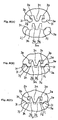
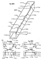
- Fig. 1(A) 1 is a pipe body of the present invention.
- the pipe body 1 has a rectangular prism shape consisting of four planes 1a, 1b, 1c, and 1d.
- the plane 1a is formed jointly with the surroundings, by way of contact of the opposite edge sections 1e, 1f.
- Fig. 1(B) which is an enlarged view of a main part before completing forming the pipe body 1
- female engagement section 1g and male engagement section 1h engaged with each other in the facing state are formed in the edge sections 1e, 1f, respectively.
- a projection 1i having a mountain shape which is projected toward an open end is formed.
- the projection 1i deforms a front end of the male engagement section 1h of a projecting shape toward both ends of the female engagement section 1g, as shown in Fig. 1(C) which is an enlarged view of the main part when completing forming the pipe body 1.
- Such deformation makes parts of the male engagement section 1h contacting with both edge sections of the female engagement section 1g, and thus, the female engagement section 1g and the male engagement section 1h are engaged with each other so that the edge sections le, 1f contact with each other closely.
- Fig. 2 shows a metal plate 1A for forming such pipe body 1.
- the sheet metal 1A is formed using a sheet shape of metal material as a source material by way of punching thereof.
- P1, P2, P3, P4 in Fig. 2 are lines representing positions to be bent by a press machine. The positions to be bent at the lines P1, P2, P3, P4 are designed in consideration of the amount of the sheet metal 1A to be expanded during the press forming.
- guide section 1j can be formed to broaden toward the open ends, so that the male engagement section 1h can be easily inserted into the female engagement section 1g.
- guide section 1k tapering off toward the end can be formed at the front end of the male engagement section 1h, so that the same advantage can be obtained.
- both guide sections 1j, 1k may be formed at the female engagement section 1g and the male engagement section 1h, respectively.
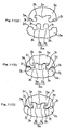
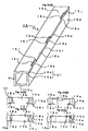
- FIG. 4(A) 2 is a pipe body of the present invention.
- the pipe body 2 has a rectangular prism shape consisting of four planes 2a, 2b, 2c, 2d.
- the plane 2a is formed jointly with the surroundings of the edge sections 2e, 2f, by way of contact of the opposite edge sections 2e, 2f.
- FIG. 4(B) which is an enlarged view of a main part before completing forming the pipe body 2
- female engagement section 2g and male engagement section 2h engaged with each other in the facing state are formed in the edge sections 2e, 2f, respectively.
- a projection 2i having a mountain shape which is projected toward the vicinity of the open end is formed.
- engaging walls 2j projected toward each other are formed, so that a diameter of the opening at the vicinity of the open end is smaller than that of the vicinity of the opening at the bottom edge section.
- the male engagement section 2h consists of a pair of divided pieces 2k of which the projected ends are divided to be guided by the projection 2i and to be bending-deformed in a direction distant from each other, as shown in Fig. 4(C) which is an enlarged view of the main part when completing forming the pipe body 2.
- the bending-deformation of the divided pieces 2k make parts thereof be in contact with the engaging walls 2j and thus, the female engagement section 2g and the male engagement section 2h are engaged with each other so that the edge sections 2e, 2f contact with each other closely, and at the same time, separation of the engagement sections is prevented.
- Fig. 5 shows a metal plate 2A for forming such pipe body 2.
- the sheet metal 2A is formed using a sheet shape of metal material as a source material by way of punching thereof.
- P1, P2, P3, P4 in Fig. 5 are lines representing positions to be bent by a press machine. The positions to be bent at the lines P1, P2, P3, P4 are designed in consideration of the amount of the sheet metal 2A to be expanded during press forming.
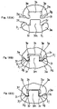
- Fig. 6(A) 3 is a pipe body of the present invention.
- the pipe body 3 has a rectangular prism shape consisting of four planes 3a, 3b, 3c, 3d and the plane 3a is formed jointly with the surroundings, by way of contact of the opposite edge sections 3e, 3f.
- convex engagement section 3g projected from the edge section 3e is formed.
- concave engagement section 3h engaged with the convex engagement section 3g in the facing state are formed, as shown in Fig. 6(B) which is an enlarged view of a main part of the pipe body before completing forming the pipe body 3.
- sloped sides 3i are formed so that the width of the convex engagement section gets smaller toward the projected end.
- sloped sides 3j are formed so that the diameter of the opening gets greater toward the open end.
- a projection 3n having a mountain shape projected toward the vicinity of the open end is formed.
- engaging walls 3p projected toward each other are formed so that a diameter of the opening at the vicinity of the open end is smaller than that of the opening of the vicinity of the bottom edge section.
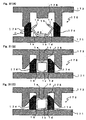
- the male engagement section 3m as shown in Fig. 6(C) which is an enlarged view of the main part of the pipe body when completing forming the pipe body 3, consists of a pair of divided pieces 3q of which the projected ends are divided to be guided by the projection 3n and to be deformed in a direction far from each other.
- the length D1 of the pair of divided pieces 3q projected from the bottom of the concave engagement section 3h is set to be greater than the depth D2 of the concave engagement section 3h, and thus, the front end of the divided pieces 3q are projected from the edge section 3f.
- the projected length D1-D2 of the divided pieces 3q from the edge section 3f can be maintained small, and the length D1 of the divided pieces 3q can be maintained as great as the length of the divided pieces 2k in the second aspect of the present invention. Also, in even a pipe body in which a width D3 of a direction crossing the edge sections 3e, 3f is small as shown in Fig. 6(A), the divided pieces 3q can be deformed without the front ends of the divided pieces 3q contacting with the bottom side of the female engagement section 3k.
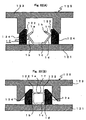
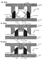
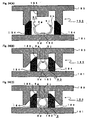
- Fig. 8(A) when the edge sections 3e, 3f get in contact with each other by a press machine, first, the front ends of the divided pieces 3q are inserted between the engaging walls 3p and the projection 3n as shown in Fig. 8(B), and then enter inside of the convex engagement sections 3g, the front ends of the engaging walls 3p are bent toward the female engagement section 3k by means of the slope of the sloped sides 3i, 3j as shown in Fig. 8(C), and the divided pieces 3q are inserted and supported between the engaging walls 3p and the projection 3n. If the female engagement section 3k and the male engagement section 3m are engaged with each other to be in contact with each other in a state that the edge sections 3e, 3f is closed, separation thereof is prevented.
- the slope angles of the sloped side 3i and the sloped side 3j arc set to be nearly equal to each other.
- the slope angles are set to be a relative angle such that the front end of the engaging walls 3p are bent to enter inside of the female engagement section 3k by the sloped side 3j.
- the uneven engagement sections 3g, 3h and at the same time projecting the divided pieces 3q from the edge section 3f, part of all members associated with the engagement are positioned on the contact line of the edge sections 3e, 3f without a gap, so that a strength for the engagement sections can be secured.
- Fig. 9 shows a metal plate 3A for forming such pipe body 3.
- the sheet metal 3A is formed using a sheet shape of metal material as a source material by way of punching thereof.
- P1, P2, P3, P4 in Fig. 9 are lines representing positions to be bent by a press machine. The positions to be bent at the lines P1, P2, P3, P4 are designed in consideration of the amount of the sheet metal 3A to be expanded during press forming.
- recessed guide section 2q is formed at the base of the male engagement section 2h(3m), or, as shown in Fig.
- recessed guide sections 2r reached from the base of the male engagement section 2h(3m) to the edge section 2f(3f) are formed, so that the divided pieces 2k can be easily bending-deformed over the whole.
- the guide sections 2m, 2n, 2p, 2q, 2r can be combined appropriately.
- the height of the projection 3n is set as small as that of the projection 2i in the second aspect, and at the same time, the outer sides of the divided pieces 3q are formed to be the sloped aides 3r, so that the width of the whole male engagement section 3m narrows toward the base thereof Therefore, as shown in Fig. 11(B) and Fig. 11(C), the engaging walls 3p can easily enter inside of the female engagement section 3k, and at the same time, the engagement of the female and male engagement sections 3k, 3m can be more secured by way of bending-deformation of the front ends of the divided pieces 3q within the female engagement section 3k.
- the projected length D3 of the divided pieces 3q is set to be greater than the above projected length D1
- the engagement of the female and male engagement sections 3k, 3m can be more secured by way of bending-deformation of the front end of the divided pieces 3q within the female engagement section 3k, as shown in Fig. 13(B) and Fig. 13(C).
- the outer sides of the divided pieces 3q are formed to be the sloped sides 3s such that the whole width of the male engagement section 3m narrows toward the front end thereof and at the same time, the sloped direction of the sloped sides 3t, 3u is set to be the opposite direction of the sloped sides 3i, 3j.
- the divided pieces 3q can easily enter inside of the female engagement section 3k, so that the sloped sides 3s open the engaging walls 3p and the sloped sides 3t and the sloped sides 3u are engaged with each other. Therefore, the uneven engagement sections 3h, 3g can be engaged with each other.
- the width of the projection 3n can get greater so that the opening angle of the divided pieces 3q by the engagement with the projection 3n can get greater. Accordingly, as shown in Fig. 15(B) and Fig. 15(C), the divided pieces 3q enter inside of the female engagement section 3k to open the engaging walls 3p, so that the sloped sides 3t and the sloped side 3u are engaged with each other. Therefore, the uneven engagement sections 3h, 3g can be engaged with each other.
- the sheet metals include one female engagement section 1g, 2g and one male engagement section 1h, 2h, respectively.
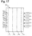
- a plurality of female engagement sections 4g and a plurality of male engagement sections 4h may be formed in the sheet metal 4A, and the same time, the projection 4i may be formed in the female engagement sections 4g (not in all the female engagement sections).
- a plurality of female engagement sections 5g and a plurality of male engagement sections 5h may be formed in the sheet metal 5A, and at the same time, the projection 5i and the engaging walls 5j may be formed in the female engagement sections 5g (not in all the female engagement sections), and the male engagement sections 5h may be divided to form the divided pieces 5k.
- a plurality of female engagement sections 6g and a plurality of male engagement sections 6h may be formed in the sheet metal 6A in turn, and at the same time, the projection 6i may be formed in the female engagement sections 6g (not in all the female engagement sections).
- a plurality of female engagement sections 7g and a plurality of male engagement sections 7h may be formed in the sheet metal 7A in turn, and at the same time, the projection 7i and the engaging walls 7j may be formed in the female engagement sections 7g (not in all the female engagement sections), and the male engagement sections 7h may be divided to form the divided pieces 7k.
- the proper material in consideration of intensity according to the purpose for use (for example, for use in a frame for fixing a body panel of a duplicator or in a frame for fixing parts) can be used as the sheet metal for forming the pipe body, and the position or the number of the engagement sections can be selected appropriately according to the purpose for use.
- holes 1m for fixation to a machine (mold) in the press processing to be explained later can be formed in the sheet metal 1A, or screw holes In for fixation to the body panel of the duplicator or for fixation to parts can be formed in the sheet metal 1A including other planes 1b, 1d, so that the range for application thereof can be varied according to the purpose for use of the pipe body 1.
- the screw holes 1n may be used as clearance holes and the holes 1m may be used commonly as the screw holes and the holes for fixation to the mold.
- the position or the number of the holes is not limited, and also may be formed even when completing forming the pipe body.
- the vicinity of the edge sections 1e, 1f of the sheet metal 1A are bent (the bent positions are the lines P1, P2) in the same direction along the edge sections 1e, 1f by means of the known press machine, to be set upright (in case of a rectangular prism, the angle of the plane 1a and the plane 16 and the angle of the plane 1a and the plane 1d are 90° ), so that a first processed piece 1B is obtained.
- the inner parts of the bent positions to be the plane 1a are further bent (the bent positions are the line P3, P4) along the edge sections 1e, 1f by means of the known press machine, so that the edge sections 1e, if are opposite to each other in the separated state.
- a second processed piece 1C is obtained.
- the gap between the edge sections 1e, 1f is set to be greater than the width of the plane 1c, so that the mold of the press machine and the second processed piece 1C can be separated easily.
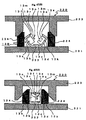
- the second processed piece 1C is set in a lower mold 111 of a press machine 110.
- the plane 1c of the second processed piece 1C is fixed by means of a pushing member 12 provided at the lower mold 111.
- the second processed piece 1C is set in the lower mold 121 of the press machine 120, as shown in Fig. 22(A).
- the vicinity of the edge sections 1e, 1f of the sheet metal 1A are bent (the bent positions are the lines P1, P2) in the same direction along the edge sections 1e, 1f by means of the known press machine, to be set upright (in case of a rectangular prism, the angle of the plane 1a and the plane 1b and the angle of the plane 1a and the plane 1d are 90° ), so that a first processed piece 1B is obtained.
- the inner sides of the bent positions to be the plane 1a are further bent (the bent positions are the line P3, P4) along the edge sections 1e, 1f by means of the known press machine, so that the edge sections le, 1f are opposite to each other in the separated state.
- a second processed piece 1C is obtained.
- the gap between the edge sections 1e, 1f is set to be greater than the width of the plane 1c, so that the mold of the press machine and the second processed piece 1C can be separated easily.
- the second processed piece 1C is set in a press machine 130.
- the plane 1c of the second processed piece 1C is fixed by means of a pushing member 132 provided at a lower mold 131.
- an upper mold 133 further goes down.
- a press member 135 of the upper mold 133 processes the third processed piece 1D in a direction perpendicular to the pressing direction of the pressing members 134.
- the explanation may be considered to be different from that of the forming method 1.
- the gap is generated according to the conditions such as the shape or the size of the female engagement section 1g and the male engagement section 1h and the quality or the thickness of the sheet metal 1A.
- the third processed pieces 1D is not the final processed piece but an interim piece. It is of course that the pressing of the pressing members 134 should not cause deformation (distortion) of the pipe body 1, in order to obtain the above advantages.
- the intensity of the pressing is set according to the above conditions such as the thickness of the sheet metal 1A.
- the vicinity of the edge sections 1e, 1f of the sheet metal 1A are bent (the bent positions are the lines P1, P2) in the same direction along the edge sections 1e, 1f by means of the known press machine, to be set upright (in case of a rectangular prism, the angle of the plane 1a and the plane 1b and the angle of the plane 1a and the plane 1d are 90° ), so that a first processed piece 1B is obtained.
- the inner sides of the bent positions to be the plane 1a are further bent (the bent positions are the line P3, P4) along the edge sections 1e, 1f by means of the known press machine, so that the edge sections 1e, 1f are opposite to each other in the separated state.
- a second processed piece 1C is obtained.
- the gap between the edge sections 1e, 1f is set to be greater than the width of the plane 1c, so that the mold of the press machine and the second processed piece 1C can be separated easily.
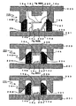
- the second processed piece 1C is set in a lower mold 141 of the press machine 140.
- the upper mold 143 goes down and the pressing members 144 of the lower mold 141 approach each other. Accordingly, the edge sections 1e, 1f approach each other, and at the same time, the plane 1c is curved in a projected direction. This curving is made by means of movement of the pressing members 144 to each other, in a state that the plane 1c is not fixed unlike the forming methods 1 and 2 and the angle ⁇ 1 between the plane 1b and the plane 1c in the second processed piece 1C is set to be an obtuse angle greater than the angle at a substantially 90° in completion of the pipe body 1 as the forming methods 1 and 2.
- the upper mold 143 further goes down.
- the pressing member 145 of the upper mold 143 process the third processed piece 1D' in a direction perpendicular to the pressing direction of the pressing members 144.
- the second processed piece 1C is set in the lower mold 151 of the press machine 150, as shown in Fig. 27(A).
- This curving is made by means of movement of the pressing members 154 to each other, in a state that the plane 1c is not fixed unlike the forming method 1 and 2 and the angle ⁇ 1 between the plane 1b and the plane 1c in the second processed piece 1C is set to be an obtuse angle.
- the pushing members 152 can be applied to forming methods other than the modified example of the forming method 1, by setting the resistive fore thereof.
- the upper mold 153 further goes down.
- the press member 155 of the upper mold 153 processes the third processed piece 1D' in a direction perpendicular to the pressing direction of the pressing members 154.
- the inner sides of the bent positions to be the plane 1a are further bent (the bent positions are the line P3, P4) along the edge sections 1e, 1f by means of the known press machine, so that the edge sections 1e, 1f are opposite to each other in the separated state.
- a second processed piece 1C' in which the plane 1c is curved in the concave direction can be obtained.
- the gap between the edge sections 1e, 1f is set to be greater than the width of the plane 1c, so that the mold of the press machine and the second processed piece 1C can be separated easily.
- the angle ⁇ 2 between the plane 1b and the plane 1c and between the plane 1d and the plane 1c is set to be an almost right angle.
- the second processed piece 1C' is set in a lower mold 161 of a press machine 160.
- the upper mold 163 further goes down.
- the press member 165 of the upper mold 163 presses the third processed piece 1D in a direction perpendicular to the pressing direction of the pressing members 164.
- the vicinity of the edge sections le, if of the sheet metal 1A are bent are the lines P1, P2 in the same direction along the edge sections 1e, 1f by means of the known press machine, to be set upright (in case of a rectangular prism, the angle of the plane 1a and the plane 1b and the angle of the plane 1a and the plane 1d are 90° ), so that a first processed piece 1B is obtained.
- the inner sides of the bent positions to be the plane 1a are further bent (the bent positions are the line P3, P4) along the edge sections 1e, 1f by means of the known press machine, so that the edge sections 1e, 1f are opposite to each other in the separated state.
- a second processed piece 1C" in which the plane 1c is curved in the concave direction can be obtained.
- the gap between the edge sections 1e, 1f is set to be greater than the width of the plane 1c, so that the mold of the press machine and the second processed piece 1C" can be separated easily.
- the angle ⁇ 3 between the plane 1b and the plane 1c and between the plane 1d and the plane 1c is set to be an obtuse angle.
- the second processed piece 1C" is set in a lower mold 171 of a press machine 170.
- the upper mold 173 further goes down.
- the press member 175 of the upper mold 173 presses the third processed piece 1D' in a direction perpendicular to the pressing direction of the pressing members 174.
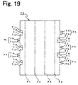
- Fig. 32 through Fig. 34 shows a hexagonal prism pipe body 9 as an example of a polygonal prism pipe body other than the above rectangular prism.
- the pipe body 9 has a hexagonal prism shape consisting of six planes 9a-9f.
- the plane 9a is formed jointly with the surroundings of the edge sections 9g, 9h, by way of contact of opposite edge sections 9g, 9h.
- a female engagement section 9i and male engagement section 9j engaged with each other in the facing state are formed in the edge sections 9g, 9h, respectively. Also, at the center of the bottom edge section of the female engagement section 9i, a projection 9k having a mountain shape which is projected toward an open end is formed. As shown in Fig. 32(B) and Fig. 32(C), the structure and the operation of the female engagement section 9i, the male engagement section 9j and the projection 9k are equal to those of the female engagement section 1g, the male engagement section lh and the projection 1i. Also, the constructions of the female engagement section 9i, the male engagement section 9j and the projection 9k may be equal to those of the female engagement section 2g, the male engagement section 2h and the projection 2i. Also, a metal plate having the same constructions as those of the above sheet metals 1A-6A can be used for forming the pipe body 9.
- the vicinity of the edge sections 9g, 9h of the sheet metal 9A are bent (the bent positions are the lines P1, P2) in the same direction along the edge sections 9g, 9h by means of the known press machine, to be set upright (in case of a hexagonal prism, the angle of the plane 9a and the plane 9b and the angle of the plane 9a and the plane 9f are 60° ), so that a first processed piece is obtained.
- the inner sides of the bent positions to be the plane 9a are further bent (the bent positions are the line P3, P4, P5, P6) along the edge sections 9g, 9h sequentially by means of the known press machine, so that the edge sections 9g, 9h are opposite to each other in the separated state. Accordingly, a second processed piece 9C is obtained.
- the gap between the edge sections 9g, 9h is set to be greater than the width of the plane 9d, so that the mold of the press machine and the second processed piece 9C (refer to Fig. 34(A)) can be separated easily.
- the second processed piece 9C is set in a lower mold 181 of a press machine 180.
- the plane 9d of the second processed piece 9C is fixed by a pushing member 182 provided at the lower mold 181.
- the upper mold 183 further goes down.
- the pressing member 185 of the upper mold 183 presses the third processed piece 9D in a direction perpendicular to the pressing direction of the pressing members 184.
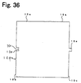
- Fig. 35 through Fig. 37 shows a cylinder pipe body 10 as an example of a polygonal prism pipe body other than the above rectangular prism.
- the pipe body 10 has a cylinder shape consisting of one curved surface 10a.
- the surface 10a is formed jointly with the surroundings of the edge sections 10b, 10c, by way of contact of the opposite edge sections 10b, 10c.
- female engagement section 10d and male engagement section 10e engaged with each other in the facing state are formed in the edge sections 10b, 10c, respectively.
- a projection 10f having a mountain shape that is projected toward an open end is formed at the center of the bottom edge section of the female engagement section 10d.
- the structure and the operation of the female engagement section 10d, the male engagement section 10e and the projection 10f are equal to those of the female engagement section 1g, the male engagement section 1h and the projection 1i.
- the constructions of the female engagement section 10d, the male engagement section 10e and the projection 10f may be equal to those of the female engagement section 2g, the male engagement section 2h and the projection 2i.
- a metal plate having the same structure as those of the above sheet metals 1A-6A can be used for forming the pipe body 10.
- the sheet metal 10A is curved by means of the known press machine to have an ellipse shape, in which the edge sections 10b, 10c are opposite to each other, thereby obtaining a first processed piece 10B as shown in Fig. 37(A).
- the first processed piece 10B is set in a lower mold 191 of a press machine 190.
- the lower side of the surface 10a is fixed by means of a pushing member 192 provided at the lower mold 191 of the press machine 190.
- 11 is a pipe body according to the fourth aspect of the present invention.
- the pipe body 11 has a rectangular prism shape consisting of four planes 11a, 11b, 11c, 11d.
- the plane 11a is formed jointly with the surroundings of the edge sections 11e, 11f, by way of contact of the parallel edge sections 11e, 11f opposite to each other.
- Projected sections 11h, 11i capable of being opposite to each other are projected from an edge section 11g perpendicular to the parallel edge sections 11e, 11f.
- Fig. 38(B) which is an enlarged view of a main part before completing forming the pipe body 11
- female engagement section 11j and male engagement section 11k engaged with each other in the facing state are formed in the projected sections 11h, 11i.
- the projected sections 11h, 11i forms a supporting plane 11p jointly with the surroundings, with the edge sections 11m, 11n thereof in contact with each other.
- a projection 11q having a mountain shape that is projected toward an open end is formed. Sloped guide sections 11r are formed at the open end side of the female engagement section 11j, to enlarge the diameter of the opening. Also, engaging walls 11s projected toward each other are formed at the female engagement section 11j, so that the diameter of the opening at the vicinity of the open end is smaller than that of the opening at the vicinity of the bottom of the female engagement section 11j.
- the male engagement section 11k consists of a pair of divided pieces 11u in which the projected ends are divided to be guided by the projection 11q and to be bending-deformed in a direction distant from each other, as shown in Fig. 38(C) which is an enlarged view of the main part when completing forming the pipe body 11.
- the bending-deformation of the divided pieces 11u make parts thereof be in contact with the engaging walls 11s and thus, the female engagement section 11j and the male engagement section 11k are engaged with each other so that the edge sections 11m, 11n get in close contact with each other.
- Fig. 39 shows a metal plate 11A for forming such pipe body 11.
- the sheet metal 11A is formed using a sheet shape of metal material as a source material by way of punching thereof
- P1, P2, P3, P4 in Fig. 39 are lines representing positions to be bent by a press machine in order to form the planes 11a-11d
- P5, P6 are lines representing positions to be bent by the press machine in order to form the supporting plane lip.
- the positions to be bent at the lines P1-P6 are designed in consideration of the amount of the sheet metal 11A to be expanded during press forming.
- holes 11v for fixation to a machine (mold) in the press processing to be explained later can be formed in, for example, the plane 11c of the sheet metal 11A.
- screw holes 11w for fixation to the body panel of the duplicator or for fixation to parts can be formed in other planes 11b, 11d, 11p.
- the range for application thereof can be varied according to the purpose for use of the pipe body 11.
- the holes 11v may be used commonly as the screw holes and the holes for fixation to the mold.
- the position or the number of the holes 11v, 11w is not limited, and may be formed even after forming the pipe body.
- the vicinity of the edge sections 11e, 11f of the sheet metal 11A are bent (the bent positions are the lines P1, P2) in the same direction along the edge sections 11e, 11f by means of the known press machine, to be set upright (in case of a rectangular prism, the angle of the plane 11a and the plane 11b and the angle of the plane 11a and the plane 11d are 90° ), and at the same time, the projected sections 11h, 11i are bent (the bent positions are the lines P6, P6) in the same direction along the edge section 11g to be set upright (in case of a rectangular prism, the angle of the plane 11b and the plane 11p and the angle of the plane 11d and the plane 11p are 90°).
- the inner sides of the bent positions to be the plane 11a are further bent (the bent positions are the line P3, P4) along the edge sections 11e, 11f by means of the known press machine, so that the edge sections 11e, 11f are opposite to each other in the separated state. Accordingly, as shown in Fig. 40(A), a first processed piece 11B is obtained. At that time, the gap between the edge sections 11e, 11f is set to be greater than the width of the plane 11c, so that the mold of the press machine and the first processed piece 11B can be separated easily.
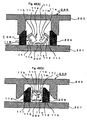
- the first processed piece 11B is set in a lower mold 201 of a press machine 200.
- the plane 11c of the first processed piece 11B is fixed by means of a pushing member 202 provided at the lower mold 201.
- the front ends of the divided pieces 11u are bending-deformed by means of the projection 11q to be separated from each other.
- This bending-deformation of the divided pieces 11u make parts thereof get in contact with engaging walls 11s, and the female engagement section 11j and the male engagement section 11k are engaged with each other to maintain the close contact of the edge sections 1m, 11n. At the same time, separation thereof is prevented.
- the engagement absorbs the spring back in a direction in which the edge sections 11m, 11n and the edge sections 11e, 11f are separated from each other, respectively.
- the pipe body 11 can be formed, in which the female engagement section 11j and the male engagement section 11k are engaged with each other and at the same time, the edge sections 11e, 11f of the plane 11a are in close contact with each other.
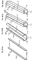
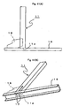
- the supporting plane 11p provided at an end of the pipe body is in contact with a base frame F1, as shown in Fig. 41(A), and the base frame F1 and the pipe body 11 are jointed together, as shown in Fig. 41(B), by means of screws N that pass through the base frame F1 and that are inserted into and coupled to the screw holes 11w (refer to Fig. 39) provided at the supporting plane 11p. Accordingly, the supporting plane 11p can be closely jointed to the base frame F1. Also, according to the kinds of the frame structure or positions, a fixed (integrated) bracket F2 may be provided at the base frame F1.
- the pipe body 12 is a pipe body according to the fifth aspect of the present invention.
- the pipe body 12 has a rectangular prism shape consisting of four planes 12a, 12b, 12c, 12d.
- the plane 12a is formed jointly with the surroundings, by way of contact of a pair of parallel edge sections 12e, 12f opposite to each other.
- a second female engagement section 12g and a second male engagement section 12h capable of being engaged with each other are provided.
- the width of the second female engagement section 12g and the width of the second male engagement section 12h are the same to be engaged with each other in their close contact state.
- the guide sections 12i are formed at the open end of the female engagement section 12g, to enlarge the diameter of the opening end thereof. Also, at the front end of the male engagement section 12h, the sloped guide sections 12j are formed such that the width of the male engagement section thins toward the front end.
- Projected sections 12m, 12n capable of being opposite to each other are projected from an edge section 12k perpendicular to the parallel edge sections 12e, 12f.
- Fig. 42(B) which is an enlarged view of a main part before completing forming the pipe body 12
- female engagement section 12o and male engagement section 12p engaged with each other in the facing state are formed in the projected sections 12m, 12n.
- the projected sections 12m, 12n forms a supporting plane 12q jointly with the surroundings, with the edge sections 12r, 12s thereof in contact with each other.
- a projection 12t having a mountain shape that is projected toward an open end is formed.
- the sloped guide sections 12u are formed at the open end of the female engagement section 120, to enlarge the diameter of the opening thereof.
- engaging walls 12v projected toward each other are formed at the female engagement section 12o, such that the diameter of the opening at the open end is smaller than that of the vicinity of the opening at the bottom edge section of the female engagement section 12o.
- the male engagement section 12p consists of a pair of divided pieces 12x of which the projected ends are divided to be guided by the projection 12t and to be bending-deformed in a direction distant from each other, as shown in Fig. 42(C) which is an enlarged view of the main part when completing forming the pipe body 12.
- the bending-deformation of the divided pieces 12x make parts thereof be in contact with engaging walls 12v and thus, the female engagement section 12o and the male engagement section 12p are engaged with each other so that the edge sections 12r, 12s get in close contact with each other.
- Fig. 43 shows a metal plate 12A for forming such pipe body 12.
- the sheet metal 12A is formed using a sheet shape of metal material as a source material by way of punching thereof
- P1, P2, P3, P4 in Fig. 43 are lines representing positions to be bent by a press machine in order to form the planes 12a-12d
- P5, P6 are lines representing positions to be bent by the press machine in order to form the supporting plane 12q.
- the positions to be bent at the lines P1-P6 are designed in consideration of the amount of the sheet metal 12A to be expanded during press forming.
- holes 12y for fixation to a machine (mold) in the press processing to be explained later can be formed, for example, in the plane 12c of the sheet metal 12A.
- screw holes 12z for fixation to the body panel of the duplicator or for fixation to parts can be formed in other planes 12b, 12d, 12q.
- the range for application thereof can be varied according to the purpose for use of the pipe body 12.
- the holes 12y may be used commonly as the screw holes and the holes for fixation to the mold.
- the position or the number of the holes 12y, 12z is not limited, and may be formed even when completing forming the pipe body.
- the vicinity of the edge sections 12e, 12f of the sheet metal 12A are bent (the bent positions are the lines P1, P2) in the same direction along the edge sections 12e, 12f by means of the known press machine, to be set upright (in case of a rectangular prism, the angle of the plane 12a and the plane 12b and the angle of the plane 12a and the planc 12d are 90° ), and at the same time, the projected sections 12m, 12n are bent (the bent positions are the lines P5, P6) in the same direction along the edge section 12k to be set upright (in case of a rectangular prism, the angle of the plane 12b and the plane 12q and the angle of the plane 12d and the plane 12q are 90° ).
- the inner sides of the bent positions to be the plane 12a are further bent (the bent positions are the line P3, P4) along the edge sections 12e, 12f by means of the known press machine, so that the edge sections 12c, 12f are opposite to each other in the separated state. Accordingly, as shown in Fig. 44(A), a first processed piece 12B is obtained. At that time, the gap between the edge sections 12e, 12f is set to be greater than the width of the plane 12c, so that the mold of the press machine and the first processed piece 12B can be separated easily.
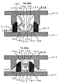
- the first processed piece 12B is set in a lower mold 211 of a press machine 210.
- the plane 12c of the first processed piece 12B is fixed by means of a pushing member 212 provided at the lower mold 211.
- the front ends of the divided pieces 12x are bending-deformed by means of the projection 12t to be separated from each other.
- This bending-deformation of the pair of the divided pieces 12x make parts thereof get in contact with engaging walls 12v, and the female engagement section 12o and the male engagement section 12p are engaged with each other to maintain the close contact of the edge sections 12r, 12s. At the same time, separation thereof is prevented.
- the engagement absorbs the spring back in a direction in which the edge sections 12r, 12s and the edge sections 12e, 12f are separated from each other, respectively.
- the pipe body 12 can be formed, in which the female engagement section 12o and the male engagement section 12p are engaged with each other and at the same time, the edge sections 12e, 12f of the plane 12a are in dose contact with each other.
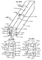
- 13 is a pipe body according to the sixth aspect of the present invention.
- the pipe body 13 has a rectangular prism shape consisting of four planes 13a, 13b, 13c, 13d.
- the plane 13a is formed jointly with the surroundings, by way of contact of a pair of parallel edge sections 13e, 13f opposite to each other.
- a second female engagement section 13g and a second male engagement section 13h capable of being engaged with each other are provided.
- the second female engagement section 13g and the second male engagement section 13h have substantially the same structure as the female engagement section 13m (corresponding to the female engagement section 13g) and the male engagement section 13n (corresponding to the male engagement section 13h) to be explained later, and thus, explanation of the female engagement section 13m and the male engagement section 13n will be quoted.
- Projected sections 13j, 13k capable of being opposite to each other are projected from an edge section 13i perpendicular to the parallel edge sections 13e, 13f.
- a female engagement section 13m and male engagement section 13n engaged with each other in the facing state are formed in the projected sections 13j, 13k. Also, the projected sections 13j, 13k forms a supporting plane 13p jointly with the surroundings of the edge sections 13q, 13r in contact with each other.
- a projection 13s having a mountain shape that is projected toward an open end is formed at the center of the bottom edge section of the female engagement section 13m.
- the sloped guide sections 13t are formed at the open end of the female engagement section 13m, to enlarge the diameter of the opening thereof.
- engaging walls 13u projected toward each other arc formed at the female engagement section 13m, such that the diameter of the opening at the vicinity of the open end is smaller than that of the opening at the vicinity of the bottom edge section of the female engagement section 13m.
- the male engagement section 13n consists of a pair of divided pieces 13w of which the projected ends are divided to be guided by the projection 13s and to be bending-deformed in a direction distant from each other, as shown in Fig. 45(C) which is an enlarged view of the main part when completing forming the pipe body 13.
- the bending-deformation of the divided pieces 13w make parts thereof be in contact with the engaging walls 13u and thus, the female engagement section 13m and the male engagement section 13n are engaged with each other so that the edge sections 13q, 13r get in close contact with each other.
- Fig. 46 shows a metal plate 13A for forming such pipe body 13.
- the sheet metal 13A is formed using a sheet shape of metal material as a source material by way of punching thereof.
- P1, P2, P3, P4 in Fig. 46 are lines representing positions to be bent by a press machine in order to form the planes 13a-13d
- P5, P6 are lines representing positions to be bent by the press machine in order to form the supporting plane 13p.
- the positions to be bent at the lines P1-P6 are designed in consideration of the amount of the sheet metal 13A to be expanded during press forming.
- holes 13x for fixation to a machine (mold) in the press processing to be explained later can be formed, for example, in the plane 13c of the sheet metal 13A.
- screw holes 13y for fixation to the body panel of the duplicator or for fixation to parts are formed in other planes 13b, 13d, 13p.
- the range for application thereof can be varied according to the purpose for use of the pipe body 13.
- the holes 13x may be used commonly as the screw holes and the holes for fixation to the mold.
- the position or the number of the holes 13x, 13y is not limited, and may be formed even when completing forming the pipe body.
- the vicinity of the edge sections 13e, 13f of the sheet metal 13A are bent (the bent positions are the lines P1, P2) in the same direction along the edge soctions 13e, 13f by means of the known press machine, to be set upright (in case of a rectangular prism, the angle of the plane 13a and the plane 13b and the angle of the plane 13a and the plane 13d are 90° ), and at the same time, the projected sections 13j, 13k are bent (the bent positions are the lines P6, P6) in the same direction along the edge section 13i to be set upright (the angle of the plane 13b and the plane 13p and the angle of the planc 13d and the plane 13p are 90° ).
- the inner sides of the bent positions to be the plane 13a are further bent (the bent positions are the line P3, P4) along the edge sections 13e, 13f by means of the known press machine, so that the edge sections 13e, 13f are opposite to each other in the separated state. Accordingly, as shown in Fig. 47(A), a first processed piece 13B is obtained. At that time, the gap between the edge sections 13e, 13f is set to be greater than the width of the plane 13c, so that the mold of the press machine and the first processed piece 13B can be separated easily.
- the first processed piece 13B is set in a lower mold 221 of a press machine 220.
- the plane 13c of the first processed piece 13B is fixed by means of a pushing member 222 provided at the lower mold 221.
- the front ends of the divided pieces 13w are bending-deformed by means of the projection 13s to be separated from each other.
- This bending-deformation of the divided pieces 13w make parts thereof get in contact with engaging walls 13u, and the female engagement section 13m and the male engagement section 13n are engaged with each other to maintain the close contact of the edge sections 13q, 13r.
- separation thereof is prevented.
- the engagement absorbs the spring back in a direction in which the edge sections 13q, 13r and the edge sections 13e, 13f are separated from each other, respectively.
- the pipe body 13 can be formed, in which the female engagement section 13m and the male engagement section 13n are engaged with each other and at the same time, the edge sections 13c, 13f of the plane 13a are in close contact with each other.
- 14 is a pipe body according to the seventh aspect of the present invention.
- the pipe body 14 has a rectangular prism shape consisting of four planes 14a, 14b, 14c, 14d.
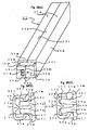
- the respective edge sections 14e, 14f of the plane 14a and the plane 14d crossing each other meet each other such that a back surface 14g of the edge section 14e contacts with an end surface 14h of the edge section 14f, thereby forming a joint 14i.
- Fig. 48(B) and (C) which are enlarged views of the main part before completing forming the pipe body 14
- female engagement section 14j and male engagement section 14k are provided at the edge sections 14e, 14f, to be opposite to each other in a direction crossing (perpendicular to) each other.
- Fig. 48(D) and (E) which are enlarged views of the main part when completing forming the pipe body 14
- the male engagement section 14k are engaged with the female engagement section 14j by means of deformation of the male engagement section 14k. Accordingly, the back surface 14g of the plane 14a and the end surface 14h of the plane 14d get in close contact with each other to form the joint 14i.
- Fig. 49(A) and (B) show a metal plate 14A for forming such pipe body 14.
- the sheet metal 14A is formed by using a sheet shape of metal material as a source material by way of punching thereof
- the female engagement section 14j is open at an end surface 14m of the plane 14a. Also, the width W1 of the female engagement section 14j at a bottom wall 14n side is set to be broader than the width W2 of the opening at the end surface 14m side as shown in Fig. 49(A). Accordingly, at both sides of the bottom wall 14n, the female engagement section 14q having the sloped surfaces 14p formed such that the gap gets smaller toward the end surface 14m.
- the width W3 of the male engagement section 14k along the length direction of the end surface 14h is set to be smaller than the width W2 of the opening. Both ends of the male engagement section 14k in the length direction are projected more than the center. Also, as shown in Fig. 49(B), the maximum projected amount H1 of the male engagement section 14k is greater than the thickness H2 of the sheet metal 14A and the recessed length H3 of the female engagement section 14j is equal to the thickness H2 of the sheet metal 14A.
- both ends of the male engagement section 14k are projected from the surface 14r of the plane 14a.
- Fig. 49 the same reference numerals given to elements of the pipe body 14 after forming are given to the corresponding elements, and explanation thereof will be omitted.
- P1, P2, P3 in Fig. 49 are lines representing positions to be bent by a press machine. The positions to be bent at the lines P1-P3 are designed in consideration of the amount of the sheet metal 14A to be expanded during press forming.
- holes 14s for fixation to a machine (mold) in the press processing to be explained later can be formed, for example, in the plane 14c of the sheet metal 14A, and screw holes 14t for fixation to the body panel of the duplicator or for fixation to parts are formed in other planes 14a, 14b, 14d.
- the range for application thereof can be varied according to the purpose for use of the pipe body 14.
- the screw holes 14t may be what is called clearance holes, and the holes 14s may be used commonly as the screw holes and the holes for fixation to the mold.
- the positions or the numbers of the holes 14s, 14t is not limited, and may be formed even when completing forming the pipe body.
- the sheet metal 14A is bent by the known press machine at the lines P1-P3 (in case of a rectangular prism, the angle of the plane 14a and the plane 14b and the angle of the plane 14b and the plane 14c are 90°, and the angle of the plane 14c and the plane 14d is an obtuse angle) to form a first processed piece 14B, as shown in Fig. 50(A).
- the first processed piece 14B is set in a lower mold 231 of a press machine 230.
- the plane 14c of the first processed piece 14B is fixed by means of a pushing member 232 provided at the lower mold 231.
- the upper mold 233 further goes down. That is, while with the pressing members 234 of the lower mold 231 fixed, the pressing member 235 of the upper mold 233 presses the second processed piece 14C in a direction perpendicular to the pressing direction of the pressing members 234, both ends of the male engagement section 14k are deformed. This deformation makes distorted parts of the male engagement section 14k enter the female engagement section 14q of the female engagement section 14j, and as a result, the female engagement section 14j and the male engagement section 14k are engaged with each other, as shown in Fig. 48(E).
- the second processed piece 14C is an interim piece between the first processed piece 14B and the pipe body 14, and is not the final pipe body. It is of course that the pressing of the pressing members 234 should not cause deformation (distortion) of the pipe body 14, in order to obtain the above advantages.
- the intensity of the pressing is set according to the conditions such as the thickness H2 and the quality of the sheet metal 14A.
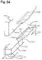
- 15 is a pipe body according to the eighth aspect of the present invention.
- the pipe body 15 has a rectangular prism shape consisting of four planes 15a, 15b, 15c, 15d.
- the respective edge sections 15e, 15f of the plane 15a and the plane 15d crossing each other (in this case, perpendicular to each other) meet each other, such that a back surface 15g of the edge section 15e is in contact with an end surface 15h of the edge section 15f, thereby forming a joint 15i.
- Fig. 51(B) and (C) which are enlarged views of the main part before completing forming the pipe body 15
- female engagement section 15j and male engagement section 15k are provided at the edge sections 15e, 15f, to be opposite to each other in a direction crossing (perpendicular to) each other.
- Fig. 51(D) and (E) which are enlarged views of the main part when completing forming the pipe body 15
- the male engagement section 15k is engaged with the female engagement section 15j by means of deformation of the male engagement section 15k. Accordingly, the back surface 15g of the plane 15a and the end surface 15h of the plane 15d get in close contact with each other to form the joint 15i.
- Fig. 52(A) and (B) show a metal plate 15A for forming such pipe body 15.
- the sheet metal 15A is formed using a sheet shape of metal material as a source material by way of punching thereof.
- the female engagement section 15j is open at an end surface 15m of the plane 15a. Also, the width W4 of the female engagement section 15j at a bottom wall 15n side is set to be broader than the width W5 of the opening at the end surface 15m side, as shown in Fig. 52(A). Accordingly, at both sides of the bottom wall 15n, the female engagement section 15q having the sloped surfaces 15p, such that the width thereof gets smaller toward the end surface 15m.
- the width W6 of the male engagement section 15k along the length direction of the end surface 15h is set to be smaller than the width W5 of the opening. Also, as shown in Fig. 52(B), the maximum projected amount H4 of the male engagement section 15k is greater than the thickness H5 of the sheet metal 15A and the recessed length H6 of the female engagement section 15j is roughly equal to the thickness H5 of the sheet metal 15A.
- Fig. 51(B) in the state that the female engagement section 15j and the male engagement section 15k are engaged with each other, the male engagement section 15k and a surface 15r of the plane 15a form roughly a plane.
- Fig. 52 the same reference numerals given to elements of the pipe body 15 after forming are given to the corresponding elements, and explanation thereof will be omitted.
- P1, P2, P3 in Fig. 52 are lines representing positions to be bent by a press machine. The positions to be bent at the lines P1-P3 are designed in consideration of the amount of the sheet metal 15A to be expanded during press forming.
- holes 15s for fixation to a machine (mold) in the press processing to be explained later can be formed in plural, for example, in the plane 15c of the sheet metal 15A, and screw holes 15t for fixation to the body panel of the duplicator or for fixation to parts are formed in other planes 15a, 15b, 15d.
- the range for application thereof can be varied according to the purpose for use.
- the screw holes 15t may be what is called clearance holes, and the holes 15s may be used commonly as the screw holes and the holes for fixation to the mold.
- the positions or the numbers of the holes 15s, 15t is not limited, and may be formed even when completing forming the pipe body.
- the sheet metal 15A is bent by the known press machine at the lines P1-P3 (in case of a rectangular prism, the angle of the plane 15a and the plane 15b and the angle of the plane 15b and the plane 15c are 90°, and the angle of the plane 15c and the plane 15d is an obtuse angle) to form a first processed piece 15B, as shown in Fig. 53(A).
- the first processed piece 15B is set in a lower mold 241 of a press machine 240.
- the plane 15c of the first processed piece 15B is fixed by means of a pushing member 242 provided at the lower mold 241.
- the upper mold 243 further goes down. That is, with the pressing members 244 of the lower mold 241 fixed, the pressing member 245 of the upper mold 243 presses the second processed piece 15C in a direction perpendicular to the pressing direction of the pressing members 244.
- a punch member 246 is projected from a position of the pressing member 245 opposite to the male engagement section 15k and the male engagement section 15k is deformed by the punch member 246.
- This deformation makes parts of the male engagement section 15k enter the female engagement section 15q of the female engagement section 16j, and as a result, the female engagement section 15j and the male engagement section 15k are engaged with each other, as shown in Fig. 51(E).
- the second processed piece 15C is an interim piece between the first processed piece 15B and the pipe body 15, and is not the final pipe body. It is of course that the pressing of the pressing members 244 should not cause deformation (distortion) of the pipe body 15, in order to obtain the above advantages.
- the intensity of the pressing is set according to the conditions such as the thickness H5 and the quality of the sheet metal 15A.
- a pipe body in which separation-prevented engagement due to deformation of at least one of the respective engagement sections absorbs the spring back in press forming so that the respective edge sections are in close contact with each other, is provided.
- engagements are sequentially carried out by means of deformation of the uneven engagement sections according to the deformation of the female and male engagement sections, and thus, the deformation and the engagement can be secured safely.
- intensity of the engaging parts can be secured in the contacting edge sections.
- the pipe body of which the edge sections closely contact with each other can be formed only by means of a simple press processing, the engagement of a pair of the female engagement section and the male engagement section due to deformation of at least one engagement section thereof can be carried out by means of the press processing, and further, in the final press process, the restoration of the pipe body and the absorption of the spring back generated in the last press process can be carried out.
Landscapes
- Engineering & Computer Science (AREA)
- Mechanical Engineering (AREA)
- General Engineering & Computer Science (AREA)
- Quick-Acting Or Multi-Walled Pipe Joints (AREA)
- Bending Of Plates, Rods, And Pipes (AREA)
- Shaping Metal By Deep-Drawing, Or The Like (AREA)
Applications Claiming Priority (8)
| Application Number | Priority Date | Filing Date | Title |
|---|---|---|---|
| JP2000027842 | 2000-02-04 | ||
| JP2000027846 | 2000-02-04 | ||
| JP2000027846 | 2000-02-04 | ||
| JP2000027845 | 2000-02-04 | ||
| JP2000027842A JP3808269B2 (ja) | 2000-02-04 | 2000-02-04 | パイプ体、パイプ体の固定構造及びパイプ体用板金、並びにパイプ体用板金を用いたパイプ体の成形方法 |
| JP2000027845A JP3844633B2 (ja) | 2000-02-04 | 2000-02-04 | パイプ体及びパイプ体用板金、及びパイプ体用板金を用いたパイプ体の成形方法 |
| JP2000387031A JP4040840B2 (ja) | 2000-02-04 | 2000-12-20 | パイプ体用板金を用いたパイプ体の成形方法 |
| JP2000387031 | 2000-12-20 |
Publications (3)
| Publication Number | Publication Date |
|---|---|
| EP1121993A2 true EP1121993A2 (fr) | 2001-08-08 |
| EP1121993A3 EP1121993A3 (fr) | 2002-04-24 |
| EP1121993B1 EP1121993B1 (fr) | 2014-01-08 |
Family
ID=27481003
Family Applications (1)
| Application Number | Title | Priority Date | Filing Date |
|---|---|---|---|
| EP01300952.7A Expired - Lifetime EP1121993B1 (fr) | 2000-02-04 | 2001-02-02 | Corps tubulaire et procédé pour sa fabrication |
Country Status (3)
| Country | Link |
|---|---|
| US (3) | US6745448B2 (fr) |
| EP (1) | EP1121993B1 (fr) |
| CN (1) | CN1258409C (fr) |
Cited By (2)
| Publication number | Priority date | Publication date | Assignee | Title |
|---|---|---|---|---|
| EP2135691A1 (fr) * | 2008-06-16 | 2009-12-23 | Jean-Marc Bouché | Tuyau de descente d`eau de gouttiére, dispositif por l`évacuation d`eau d`une toiture et procédé de fabrication dudit tuyau |
| CN105033079A (zh) * | 2015-08-24 | 2015-11-11 | 鞍山松意机器人制造有限公司 | 一种全自动扣缝装置 |
Families Citing this family (36)
| Publication number | Priority date | Publication date | Assignee | Title |
|---|---|---|---|---|
| CN100469482C (zh) * | 2000-02-04 | 2009-03-18 | 株式会社理光 | 管、制管方法和设备 |
| JP3914103B2 (ja) | 2002-07-01 | 2007-05-16 | 株式会社リコー | パイプ体の製造方法及びパイプ体 |
| JP4299103B2 (ja) * | 2003-11-07 | 2009-07-22 | 株式会社リコー | 取り付け方法及びこの取り付け方法を用いた光走査装置及びこれを用いた画像形成装置 |
| JP2006289496A (ja) * | 2005-03-17 | 2006-10-26 | Seiko Epson Corp | 円筒軸とその製造方法 |
| US7866911B2 (en) * | 2005-10-07 | 2011-01-11 | Zurn Industries, Llc | Slotted drain |
| DE202008001489U1 (de) * | 2008-02-02 | 2008-04-03 | Acument Gmbh & Co. Ohg | Fügeverbindung für Blechumformteile und Durchzug mit einer solchen Fügeverbindung |
| US7919893B2 (en) * | 2008-05-14 | 2011-04-05 | Sunonwealth Electric Machine Industry Co., Ltd. | Permanent magnet rotor with annular rib coupling |
| US20090284092A1 (en) * | 2008-05-14 | 2009-11-19 | Sunonwealth Electric Machine Industry Co., Ltd. | Motor Rotor |
| JP5378738B2 (ja) * | 2008-09-25 | 2013-12-25 | Jfeスチール株式会社 | 閉構造部材の製造方法、プレス成形装置 |
| JP5433243B2 (ja) * | 2009-02-05 | 2014-03-05 | 東プレ株式会社 | 角パイプ、フレーム構造体、角パイプの製造方法、および、角パイプの製造装置 |
| JP2011088699A (ja) * | 2009-10-21 | 2011-05-06 | Seiko Epson Corp | 円筒軸、搬送ローラー、搬送ユニット及び印刷装置 |
| JP5267187B2 (ja) | 2009-02-13 | 2013-08-21 | セイコーエプソン株式会社 | 円筒軸、搬送ローラー、搬送ユニット、及び印刷装置 |
| US9180702B2 (en) * | 2009-02-13 | 2015-11-10 | Seiko Epson Corporation | Cylindrical shaft, transport roller, transport unit and printing apparatus |
| JP5453831B2 (ja) | 2009-02-13 | 2014-03-26 | セイコーエプソン株式会社 | 印刷装置 |
| JP2011073420A (ja) * | 2009-10-02 | 2011-04-14 | Seiko Epson Corp | 印刷装置 |
| DE102009060212A1 (de) * | 2009-12-23 | 2011-06-30 | KS Gleitlager GmbH, 68789 | Gerolltes Gleitlagerelement und Flachmaterialabschnitt und Verfahren zu seiner Herstellung |
| JP2011184149A (ja) * | 2010-03-09 | 2011-09-22 | Seiko Epson Corp | 搬送装置及び印刷装置 |
| JP5429084B2 (ja) * | 2010-07-09 | 2014-02-26 | 住友電装株式会社 | チューブ加工装置及びチューブフラット化物製造方法 |
| USD667350S1 (en) * | 2010-11-18 | 2012-09-18 | Jeffrey Shell | Slide guard |
| DE102011087530A1 (de) | 2011-12-01 | 2013-06-06 | Ks Gleitlager Gmbh | Flachmaterialabschnitt für die Herstellung eines buchsenförmigen Gleitlagerelements sowie Gleitlagerbuchse |
| WO2013094580A1 (fr) * | 2011-12-21 | 2013-06-27 | 本田技研工業株式会社 | Structure de montage de bras de suspension |
| CN103182629A (zh) * | 2011-12-31 | 2013-07-03 | 上海和达汽车配件有限公司 | 高强度钢不等壁厚管件和异型管件的成型方法 |
| JP2013212531A (ja) * | 2012-04-04 | 2013-10-17 | Denso Corp | かしめ結合方法およびかしめ結合構造 |
| CN102825100A (zh) * | 2012-09-20 | 2012-12-19 | 上海和达汽车配件有限公司 | 一种不等壁厚异型管件的制作方法 |
| JP6067327B2 (ja) * | 2012-10-29 | 2017-01-25 | 日野自動車株式会社 | 扁平管製造方法 |
| WO2014145649A1 (fr) * | 2013-03-15 | 2014-09-18 | Abt, Inc. | Bonde d'évacuation de pont et son procédé de fabrication |
| CN103272960B (zh) * | 2013-06-04 | 2015-06-17 | 浙江炜驰汽车零部件股份有限公司 | 无焊接的圆管成型方法 |
| KR102343765B1 (ko) | 2017-03-15 | 2021-12-27 | 닛폰세이테츠 가부시키가이샤 | ??칭 부재의 제조 방법 및 ??칭 부재 |
| JP7110186B2 (ja) * | 2017-05-31 | 2022-08-01 | キヤノン株式会社 | 筒状体及び筒状体の製造方法 |
| CN110159053A (zh) * | 2019-06-25 | 2019-08-23 | 中电建成都铁塔有限公司 | 一种输电线多棱杆结构及其制作工艺 |
| CN110385953B (zh) * | 2019-07-31 | 2021-11-02 | 天人汽车底盘(芜湖)股份有限公司 | 板料成型的高强度扭力横梁 |
| DE102019217509B4 (de) * | 2019-11-13 | 2024-07-25 | Simplon Fahrrad Gmbh | Verfahren zur Herstellung eines zumindest teilbereichsweise geschlossenen Blechprofils aus Metall |
| EP4090398A1 (fr) * | 2020-01-13 | 2022-11-23 | Amgen Inc. | Dispositifs de retrait de protection d'aiguille, dispositifs d'administration de médicament et méthodes associées |
| CN111729948B (zh) * | 2020-07-21 | 2025-08-26 | 江苏宏宝优特管业制造有限公司 | 一种方形钢管成型装置 |
| JP7682757B2 (ja) * | 2021-09-30 | 2025-05-26 | キヤノン株式会社 | 円筒体および機器 |
| CN114951364B (zh) * | 2022-03-21 | 2023-10-13 | 山东合利工程机械有限公司 | 矩形管一体成型模具及其液压成型机和成型方法 |
Family Cites Families (34)
| Publication number | Priority date | Publication date | Assignee | Title |
|---|---|---|---|---|
| US578800A (en) * | 1897-03-16 | Sheet-metal tube | ||
| US578801A (en) | 1897-03-16 | Sheet-iv | ||
| US3273601A (en) * | 1966-09-20 | Stamped tubular product and method of making the same | ||
| US1016584A (en) * | 1911-01-14 | 1912-02-06 | Charles P Shepherd | Sheet-metal work. |
| US1344105A (en) * | 1915-06-12 | 1920-06-22 | Durand Steel Locker Company | Art of forming tubes |
| US2115441A (en) * | 1937-02-01 | 1938-04-26 | Trailer Company Of America | Method of forming tubular structures from sheet metal |
| US2339219A (en) * | 1940-08-03 | 1944-01-11 | Crowiey Edward Chase | Method and machine for making tubes |
| US2330207A (en) * | 1941-01-22 | 1943-09-28 | Contrinental Can Company Inc | Method of making sheet metal containers |
| US2544266A (en) * | 1948-06-01 | 1951-03-06 | Nat Electric Prod Corp | Method of making outlet boxes |
| US2762117A (en) * | 1953-07-13 | 1956-09-11 | Gen Motors Corp | Method of forming an interlocking bushing |
| US2855252A (en) * | 1954-09-29 | 1958-10-07 | Clevite Corp | Clinched butt bushing |
| US3043003A (en) * | 1958-03-03 | 1962-07-10 | Lever David Allan | Method for forming joint |
| DE2830400C2 (de) * | 1978-07-11 | 1982-11-25 | Skf Kugellagerfabriken Gmbh, 8720 Schweinfurt | Kugellager zur längsbeweglichen Lagerung von Maschinenteilen |
| US4301348A (en) * | 1978-11-17 | 1981-11-17 | Kabushikikaisha Nakazima | Process for producing large-sized rectangular or square steel pipes |
| US4538647A (en) * | 1981-04-23 | 1985-09-03 | Saurenman Phillip E | Interlocked metal seam structure with in-plane stabilization |
| JPS57195909A (en) | 1981-05-28 | 1982-12-01 | Japan Aviation Electron | Adhesion of metal plate |
| US4543297A (en) * | 1981-11-04 | 1985-09-24 | Saurenman Phillip E | Stiff metal ring and process for making it |
| DE3206126A1 (de) * | 1982-02-20 | 1983-09-01 | Skf Kugellagerfabriken Gmbh | Verfahren zum herstellen eines waermebehandelten lagerringes und nach diesem verfahren hergestellter lagerring |
| JPS6046831A (ja) | 1984-07-10 | 1985-03-13 | Sango:Kk | 消音器における構成パイプの接合方法 |
| DE8536655U1 (de) | 1985-12-28 | 1986-02-27 | Metallwarenfabrik König GmbH, 7560 Gaggenau | Vorrichtung zur Herstellung von exakt kalibrierten Rohrstücken aus Blech |
| JPS6380045A (ja) | 1986-09-19 | 1988-04-11 | Mazda Motor Corp | エンジンのノツキング制御装置 |
| JPS63154236A (ja) | 1986-12-18 | 1988-06-27 | Toyota Motor Corp | パイプの製造方法 |
| JPS63303218A (ja) * | 1987-06-02 | 1988-12-09 | Daido Metal Kogyo Kk | 合わせ目両端の締結部が同形状の締結形巻きブシュ軸受 |
| DE8714280U1 (de) * | 1987-10-27 | 1987-12-17 | Mächtle-Wöhler, Margot, 70825 Korntal-Münchingen | Vierkantrohr |
| US5104026A (en) * | 1990-03-26 | 1992-04-14 | Shape Corporation | Apparatus for roll-forming an automotive bumper |
| JP2982030B2 (ja) | 1991-09-26 | 1999-11-22 | 横河電機株式会社 | ケースの形成方法とその装置 |
| AT402478B (de) * | 1993-08-02 | 1997-05-26 | Ehrenleitner Franz | Geschlossenes profil |
| JP3347573B2 (ja) * | 1996-04-05 | 2002-11-20 | トヨタ自動車株式会社 | 断面多角形閉状態の管の製造方法及びそのための型 |
| FI965070A0 (fi) * | 1996-12-17 | 1996-12-17 | Samesor Smt International Oy | En utrustning foer rullforming av balkprodukter foer metallplaoten |
| JP3497057B2 (ja) | 1997-02-05 | 2004-02-16 | ナカジマ鋼管株式会社 | 角形鋼管製造用の成形プレス装置 |
| US6391414B1 (en) * | 1997-03-07 | 2002-05-21 | Pharmacia Ab | Structure and method for joining parts |
| JP4149027B2 (ja) | 1998-04-15 | 2008-09-10 | 東プレ株式会社 | 角パイプの製造方法 |
| US6216514B1 (en) * | 1999-01-22 | 2001-04-17 | The Bradbury Company, Inc. | Roll-forming machine |
| CN100469482C (zh) | 2000-02-04 | 2009-03-18 | 株式会社理光 | 管、制管方法和设备 |
-
2001
- 2001-02-02 US US09/776,118 patent/US6745448B2/en not_active Expired - Lifetime
- 2001-02-02 EP EP01300952.7A patent/EP1121993B1/fr not_active Expired - Lifetime
- 2001-02-05 CN CN01103606.0A patent/CN1258409C/zh not_active Expired - Lifetime
-
2003
- 2003-12-29 US US10/748,092 patent/US7044169B2/en not_active Expired - Lifetime
-
2006
- 2006-03-20 US US11/385,643 patent/US7318455B2/en not_active Expired - Lifetime
Non-Patent Citations (1)
| Title |
|---|
| None |
Cited By (2)
| Publication number | Priority date | Publication date | Assignee | Title |
|---|---|---|---|---|
| EP2135691A1 (fr) * | 2008-06-16 | 2009-12-23 | Jean-Marc Bouché | Tuyau de descente d`eau de gouttiére, dispositif por l`évacuation d`eau d`une toiture et procédé de fabrication dudit tuyau |
| CN105033079A (zh) * | 2015-08-24 | 2015-11-11 | 鞍山松意机器人制造有限公司 | 一种全自动扣缝装置 |
Also Published As
| Publication number | Publication date |
|---|---|
| EP1121993B1 (fr) | 2014-01-08 |
| CN1258409C (zh) | 2006-06-07 |
| EP1121993A3 (fr) | 2002-04-24 |
| US20060185751A1 (en) | 2006-08-24 |
| US20040140011A1 (en) | 2004-07-22 |
| US20010020491A1 (en) | 2001-09-13 |
| US7318455B2 (en) | 2008-01-15 |
| US6745448B2 (en) | 2004-06-08 |
| US7044169B2 (en) | 2006-05-16 |
| CN1308999A (zh) | 2001-08-22 |
Similar Documents
| Publication | Publication Date | Title |
|---|---|---|
| EP1121993A2 (fr) | Corps tubulaire et procédé pour sa fabrication | |
| US5487219A (en) | Method of manufacturing engine cradles | |
| US5829219A (en) | Frame forming member | |
| CA2920881C (fr) | Procede de fabrication de produit forme sous presse et appareil de formage sous presse | |
| JP2006131125A (ja) | 隔壁部材 | |
| KR101810109B1 (ko) | 종방향 플랜지를 구비하는 중공 프로파일 부재 제조 방법 | |
| WO2018221601A1 (fr) | Corps cylindrique et procédé de fabrication de corps cylindrique | |
| JP2004359137A (ja) | 車両用ドアのインパクトプロテクションビーム、その製造方法、およびu曲げ方法 | |
| JPH10236248A (ja) | 自動車用バンパービームおよびその製造方法 | |
| JP5392066B2 (ja) | フロントピラーの構造及びフロントピラー構成部材の製造方法 | |
| JP2007029966A (ja) | 部分オーバーラップ成形法 | |
| EP0799656A2 (fr) | Procédé et dispositif de fabrication de tubes de section polygonale | |
| JP3183422B2 (ja) | 継手及びその製造方法 | |
| JP4040840B2 (ja) | パイプ体用板金を用いたパイプ体の成形方法 | |
| US20050244666A1 (en) | Tubular blank | |
| JP7244192B2 (ja) | 筒状部品およびその製造方法 | |
| JP2003245717A (ja) | パイプ体製造方法及びパイプ体 | |
| US20200246853A1 (en) | Method of manufacturing pipe | |
| JP4527125B2 (ja) | パイプ体の製造方法及びパイプ体 | |
| JP7854353B2 (ja) | プレス成形品、プレス成形品の接合構造及びシートフレーム | |
| US20250256320A1 (en) | Panel body manufacturing method | |
| US5750236A (en) | Apparatus and method for forming compound shaped surfaces | |
| EP3932584B1 (fr) | Procédé de fabrication d'un écran thermique multicouche | |
| JP2022146743A (ja) | 構造体および構造体の製造方法 | |
| JP2017194083A (ja) | 金属板の結合構造、引出し及びキャビネット |
Legal Events
| Date | Code | Title | Description |
|---|---|---|---|
| PUAI | Public reference made under article 153(3) epc to a published international application that has entered the european phase |
Free format text: ORIGINAL CODE: 0009012 |
|
| 17P | Request for examination filed |
Effective date: 20010301 |
|
| AK | Designated contracting states |
Kind code of ref document: A2 Designated state(s): DE FR GB Kind code of ref document: A2 Designated state(s): AT BE CH CY DE DK ES FI FR GB GR IE IT LI LU MC NL PT SE TR |
|
| AX | Request for extension of the european patent |
Free format text: AL;LT;LV;MK;RO;SI |
|
| PUAL | Search report despatched |
Free format text: ORIGINAL CODE: 0009013 |
|
| AK | Designated contracting states |
Kind code of ref document: A3 Designated state(s): AT BE CH CY DE DK ES FI FR GB GR IE IT LI LU MC NL PT SE TR |
|
| AX | Request for extension of the european patent |
Free format text: AL;LT;LV;MK;RO;SI |
|
| AKX | Designation fees paid |
Free format text: DE FR GB |
|
| 17Q | First examination report despatched |
Effective date: 20041201 |
|
| GRAP | Despatch of communication of intention to grant a patent |
Free format text: ORIGINAL CODE: EPIDOSNIGR1 |
|
| INTG | Intention to grant announced |
Effective date: 20130719 |
|
| GRAS | Grant fee paid |
Free format text: ORIGINAL CODE: EPIDOSNIGR3 |
|
| GRAA | (expected) grant |
Free format text: ORIGINAL CODE: 0009210 |
|
| AK | Designated contracting states |
Kind code of ref document: B1 Designated state(s): DE FR GB |
|
| REG | Reference to a national code |
Ref country code: GB Ref legal event code: FG4D |
|
| REG | Reference to a national code |
Ref country code: DE Ref legal event code: R096 Ref document number: 60148543 Country of ref document: DE Effective date: 20140220 |
|
| REG | Reference to a national code |
Ref country code: DE Ref legal event code: R097 Ref document number: 60148543 Country of ref document: DE |
|
| PLBE | No opposition filed within time limit |
Free format text: ORIGINAL CODE: 0009261 |
|
| STAA | Information on the status of an ep patent application or granted ep patent |
Free format text: STATUS: NO OPPOSITION FILED WITHIN TIME LIMIT |
|
| 26N | No opposition filed |
Effective date: 20141009 |
|
| REG | Reference to a national code |
Ref country code: DE Ref legal event code: R097 Ref document number: 60148543 Country of ref document: DE Effective date: 20141009 |
|
| REG | Reference to a national code |
Ref country code: FR Ref legal event code: PLFP Year of fee payment: 16 |
|
| REG | Reference to a national code |
Ref country code: FR Ref legal event code: PLFP Year of fee payment: 17 |
|
| REG | Reference to a national code |
Ref country code: FR Ref legal event code: PLFP Year of fee payment: 18 |
|
| PGFP | Annual fee paid to national office [announced via postgrant information from national office to epo] |
Ref country code: DE Payment date: 20200219 Year of fee payment: 20 Ref country code: GB Payment date: 20200219 Year of fee payment: 20 |
|
| PGFP | Annual fee paid to national office [announced via postgrant information from national office to epo] |
Ref country code: FR Payment date: 20200219 Year of fee payment: 20 |
|
| REG | Reference to a national code |
Ref country code: DE Ref legal event code: R071 Ref document number: 60148543 Country of ref document: DE |
|
| REG | Reference to a national code |
Ref country code: GB Ref legal event code: PE20 Expiry date: 20210201 |
|
| PG25 | Lapsed in a contracting state [announced via postgrant information from national office to epo] |
Ref country code: GB Free format text: LAPSE BECAUSE OF EXPIRATION OF PROTECTION Effective date: 20210201 |