EP1122036A2 - Vorrichtung zur synchronen Steuerung für Roboter - Google Patents
Vorrichtung zur synchronen Steuerung für Roboter Download PDFInfo
- Publication number
- EP1122036A2 EP1122036A2 EP01300823A EP01300823A EP1122036A2 EP 1122036 A2 EP1122036 A2 EP 1122036A2 EP 01300823 A EP01300823 A EP 01300823A EP 01300823 A EP01300823 A EP 01300823A EP 1122036 A2 EP1122036 A2 EP 1122036A2
- Authority
- EP
- European Patent Office
- Prior art keywords
- robot
- data
- positioning controller
- robots
- control device
- Prior art date
- Legal status (The legal status is an assumption and is not a legal conclusion. Google has not performed a legal analysis and makes no representation as to the accuracy of the status listed.)
- Granted
Links
Images


Classifications
-
- B—PERFORMING OPERATIONS; TRANSPORTING
- B25—HAND TOOLS; PORTABLE POWER-DRIVEN TOOLS; MANIPULATORS
- B25J—MANIPULATORS; CHAMBERS PROVIDED WITH MANIPULATION DEVICES
- B25J9/00—Program-controlled manipulators
- B25J9/16—Program controls
- B25J9/1679—Program controls characterised by the tasks executed
- B25J9/1682—Dual arm manipulator; Coordination of several manipulators
-
- G—PHYSICS
- G05—CONTROLLING; REGULATING
- G05B—CONTROL OR REGULATING SYSTEMS IN GENERAL; FUNCTIONAL ELEMENTS OF SUCH SYSTEMS; MONITORING OR TESTING ARRANGEMENTS FOR SUCH SYSTEMS OR ELEMENTS
- G05B19/00—Program-control systems
- G05B19/02—Program-control systems electric
- G05B19/418—Total factory control, i.e. centrally controlling a plurality of machines, e.g. direct or distributed numerical control [DNC], flexible manufacturing systems [FMS], integrated manufacturing systems [IMS] or computer integrated manufacturing [CIM]
- G05B19/41815—Total factory control, i.e. centrally controlling a plurality of machines, e.g. direct or distributed numerical control [DNC], flexible manufacturing systems [FMS], integrated manufacturing systems [IMS] or computer integrated manufacturing [CIM] characterised by the cooperation between machine tools, manipulators and conveyor or other workpiece supply system, workcell
- G05B19/41825—Total factory control, i.e. centrally controlling a plurality of machines, e.g. direct or distributed numerical control [DNC], flexible manufacturing systems [FMS], integrated manufacturing systems [IMS] or computer integrated manufacturing [CIM] characterised by the cooperation between machine tools, manipulators and conveyor or other workpiece supply system, workcell machine tools and manipulators only, machining centre
-
- G—PHYSICS
- G05—CONTROLLING; REGULATING
- G05B—CONTROL OR REGULATING SYSTEMS IN GENERAL; FUNCTIONAL ELEMENTS OF SUCH SYSTEMS; MONITORING OR TESTING ARRANGEMENTS FOR SUCH SYSTEMS OR ELEMENTS
- G05B2219/00—Program-control systems
- G05B2219/30—Nc systems
- G05B2219/33—Director till display
- G05B2219/33083—Clock for microprocessor synchronized with pulses from encoder
-
- G—PHYSICS
- G05—CONTROLLING; REGULATING
- G05B—CONTROL OR REGULATING SYSTEMS IN GENERAL; FUNCTIONAL ELEMENTS OF SUCH SYSTEMS; MONITORING OR TESTING ARRANGEMENTS FOR SUCH SYSTEMS OR ELEMENTS
- G05B2219/00—Program-control systems
- G05B2219/30—Nc systems
- G05B2219/39—Robotics, robotics to robotics hand
- G05B2219/39105—Manipulator cooperates with moving machine, like press brake
-
- G—PHYSICS
- G05—CONTROLLING; REGULATING
- G05B—CONTROL OR REGULATING SYSTEMS IN GENERAL; FUNCTIONAL ELEMENTS OF SUCH SYSTEMS; MONITORING OR TESTING ARRANGEMENTS FOR SUCH SYSTEMS OR ELEMENTS
- G05B2219/00—Program-control systems
- G05B2219/30—Nc systems
- G05B2219/45—Nc applications
- G05B2219/45142—Press-line
-
- Y—GENERAL TAGGING OF NEW TECHNOLOGICAL DEVELOPMENTS; GENERAL TAGGING OF CROSS-SECTIONAL TECHNOLOGIES SPANNING OVER SEVERAL SECTIONS OF THE IPC; TECHNICAL SUBJECTS COVERED BY FORMER USPC CROSS-REFERENCE ART COLLECTIONS [XRACs] AND DIGESTS
- Y02—TECHNOLOGIES OR APPLICATIONS FOR MITIGATION OR ADAPTATION AGAINST CLIMATE CHANGE
- Y02P—CLIMATE CHANGE MITIGATION TECHNOLOGIES IN THE PRODUCTION OR PROCESSING OF GOODS
- Y02P90/00—Enabling technologies with a potential contribution to greenhouse gas [GHG] emissions mitigation
- Y02P90/02—Total factory control, e.g. smart factories, flexible manufacturing systems [FMS] or integrated manufacturing systems [IMS]
-
- Y—GENERAL TAGGING OF NEW TECHNOLOGICAL DEVELOPMENTS; GENERAL TAGGING OF CROSS-SECTIONAL TECHNOLOGIES SPANNING OVER SEVERAL SECTIONS OF THE IPC; TECHNICAL SUBJECTS COVERED BY FORMER USPC CROSS-REFERENCE ART COLLECTIONS [XRACs] AND DIGESTS
- Y10—TECHNICAL SUBJECTS COVERED BY FORMER USPC
- Y10T—TECHNICAL SUBJECTS COVERED BY FORMER US CLASSIFICATION
- Y10T29/00—Metal working
- Y10T29/49—Method of mechanical manufacture
- Y10T29/49826—Assembling or joining
- Y10T29/49828—Progressively advancing of work assembly station or assembled portion of work
- Y10T29/49829—Advancing work to successive stations [i.e., assembly line]
-
- Y—GENERAL TAGGING OF NEW TECHNOLOGICAL DEVELOPMENTS; GENERAL TAGGING OF CROSS-SECTIONAL TECHNOLOGIES SPANNING OVER SEVERAL SECTIONS OF THE IPC; TECHNICAL SUBJECTS COVERED BY FORMER USPC CROSS-REFERENCE ART COLLECTIONS [XRACs] AND DIGESTS
- Y10—TECHNICAL SUBJECTS COVERED BY FORMER USPC
- Y10T—TECHNICAL SUBJECTS COVERED BY FORMER US CLASSIFICATION
- Y10T29/00—Metal working
- Y10T29/53—Means to assemble or disassemble
- Y10T29/53313—Means to interrelatedly feed plural work parts from plural sources without manual intervention
- Y10T29/53365—Multiple station assembly apparatus
-
- Y—GENERAL TAGGING OF NEW TECHNOLOGICAL DEVELOPMENTS; GENERAL TAGGING OF CROSS-SECTIONAL TECHNOLOGIES SPANNING OVER SEVERAL SECTIONS OF THE IPC; TECHNICAL SUBJECTS COVERED BY FORMER USPC CROSS-REFERENCE ART COLLECTIONS [XRACs] AND DIGESTS
- Y10—TECHNICAL SUBJECTS COVERED BY FORMER USPC
- Y10T—TECHNICAL SUBJECTS COVERED BY FORMER US CLASSIFICATION
- Y10T29/00—Metal working
- Y10T29/53—Means to assemble or disassemble
- Y10T29/53313—Means to interrelatedly feed plural work parts from plural sources without manual intervention
- Y10T29/53383—Means to interrelatedly feed plural work parts from plural sources without manual intervention and means to fasten work parts together
Definitions
- the present invention relates to a work-transporting robot provided between a plurality of press machines; particularly, the present invention relates to a synchronous control device for a plurality of robots.
- press systems where pressing by a plurality of press machines occurs by transporting a work item in sequence using a work transport line.
- the work transport line involves a plurality of robots, a material supply device at an upstream side, a product removal device at a downstream side, and a plurality of intermediate stages.
- Each robot transports a work item in a sequential manner between the intermediate stages.
- Each robot, the material supply device, and the product removal device are conventionally operated in an electronically linked manner, as will be described.
- each of the robots travels to a work retrieve position, from a home position, retrieves the work item, advances to a work release position, releases the work item, and returns to the home position.
- the position of the robots is matched at both a midpoint in the advance motion and the return motion.
- the midpoints are also linked to the motion of the material supply device and the product removal device, as will be explained.
- a transporting speed for each of the robots may differ as a result in several factors. These factors include, differences in the weight of each work item, differences in the advance and return motions, and differences in retrieve and release motions.
- each of the robots must be operated alone in order to avoid interference with adjacent robots or other devices.
- a conventional flow control diagram for the work transport line includes a master board 17 linking a programmable controller 18 to three robots 3a', 3b', and 3c'. Additional conventional links to the material supply device (not shown) and the material removal device (not shown) are omitted for clarity.
- Each robot 3a', 3b', and 3c' includes a programmable controller 16, a servo amp 15 and a servo motor 14 each in electronic communication with the other.
- Each robot 3a', 3b', and 3c' is linked to and controlled by programmable controller 18, through corresponding programmable controller 16.
- Electronic communications pass from programmable controller 16, by corresponding servo amp 15, to servo motor 14.
- Each servo motor 14 acts as a drive source for each corresponding robot 3a', 3b', and 3c' through a mechanical construction member (not shown).
- programmable controller 18 signals each robot 3a', 3b', and 3c', through corresponding programmable controllers 16, to go to the corresponding work retrieve positions, retrieve the work items, and advance to the advance midpoints and wait. Once programmable controllers 18, 16 confirm that all robots 3a', 3b', and 3c' have reached the advance midpoints, each robot 3a', 3b' and 3c' advances to the corresponding work release position and releases the work items.
- robots 3a', 3b', and 3c' After releasing the work items, robots 3a', 3b', and 3c' return to the corresponding return midpoints and wait. Once programmable controllers 18, 16 confirm that all robots 3a', 3b', and 3c' have reached the corresponding return midpoints, all robots 3a', 3b', and 3c' wait for further signals from programmable controller 18.
- the return midpoint is also a home position for robots 3a', 3b', and 3c'.
- the corresponding press machines are activated. Repetition of the above described conventional process advances corresponding work items through the press system (not shown).
- robots 3a', 3b', and 3c' are operated individually in an inching operation (not shown). Since adjacent robots 3a', 3b', and 3c' are not synchronized, the inching operation is conducted by individual inching movements (not shown). In this case, to avoid interference between adjacent robots 3a', 3b', and 3c', the range of inching movement is limited. As a result, adjustment, exchange of dies, or other maintenance activity is complex and time consuming thereby increasing operating costs.
- a synchronous control device receives expansion data describing robot movement, stores the expansion data in a storage element, and in accordance with an internal clock or encoder equivalent, outputs the expansion data to a positioning controller through an output element to continuously control robot movement.
- a synchronous control device comprising: an internal clock being of a type equivalent to a speed of an outside element, means for storing data characterizing a path and the speed of the outside element, means for outputting the data to a positioning controller in accordance with the internal clock, and the positioning controller receiving the data and controlling the outside element, whereby the outside element is continuously synchronized with the data.
- a synchronous control device comprising: means for storing data characterizing a path of a robot, a clock being of a type equivalent to a speed of said robot, means for outputting the data to a positioning controller in accordance with the clock, and the positioning controller commanding a control source for the robot, whereby the robot is continuously synchronized with the data.
- a synchronous control device wherein: the clock is replaced with an encoder signal detecting a crank position of the robot.
- a synchronous control device for a robot being a synchronous control device for a work-transporting robot provided between press machines and having a drive source, comprising: an internal clock being of a type equivalent to a motion speed of the robot, a positioning controller being of a type which outputs a command signal to a drive source for the robot, means for storage being of a type which stores data describing a path of the robot, and means for output being of a type which outputs the data to the positioning controller in accordance with the internal clock.
- a synchronous control device wherein: the internal clock is replaced with a signal of an encoder detecting a crank angle of a press machine.
- a synchronous control device wherein: the motion speed of the robot is a work transport speed.
- the drive source of the robot is a servo amp controlling a servo motor.
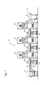
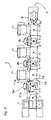
- a first arrangement of a press system 1 includes three press machines 2a, 2b, and 2c for conducting pressing work on a work item (not shown), and a work transport line 7, for transporting the work item through press system 1 from an upstream side (to the left facing the page) to a downstream side.
- Robots 3a, 3b, and 3c are each provided with a corresponding feed bar 11a, on a left side (facing the page) and a feed bar 11b, on a right side (facing the page). Feed bars 11a, 11b are movable to the left, right, up, and down with respect to each corresponding robot 3a, 3b, and 3c. Robots 3a, 3b, and 3c are additionally provided with servo motor 14 (not shown) which acts as a drive source for corresponding feed bars 11a, 11b.
- Each feed bar 11a, 11b has a vacuum cup 13 affixed by a finger 12 to each corresponding feed bar 11a, 11b for each robot 3a, 3b, and 3c.
- Vacuum cups 13 is actuated by an air compression device (not shown).
- An intermediate stage 4a, 4b, and 4c is positioned in front of each corresponding robot 3a, 3b, and 3c to temporarily receive work items during the pressing process, as will be explained.
- Work transport line 7 includes, from upstream side to downstream side, material supply device 5, respective robots 3a, 3b, and 3c, with corresponding intermediate stages 4a, 4b, and 4c, and product removal device 6.
- stages S1 through S8 are provided in the first arrangement and correspond to each sequential position where the work items (not shown) are positioned during operation.
- material supply device 5 places the work item at stage S1.
- feed bar 11a of robot 3a transports the work item using vacuum cup 13 from stage S1 to stage S2.
- feed bar 11b of robot 3a transports the work item, using vacuum cup 13, from stage S2 to stage S3 where the work item is pressed by press machine 2a.
- the work item continues to be transported along work transport line 7 by respective feed bars 11a, 11b of corresponding robots 3b and 3c until reaching stage S8 where product removal device 6 removes the work item.
- Fig. 3A which describes the transport motion of individual feed bars 11a, 11b for respective robots 3a, 3b, and 3c.
- feed bars 11a, 11b move continuously from a home position to a work retrieval position and, using vacuum cup 13, retrieve and hold the work item (not shown).
- feed bars 11a, 11b move continuously from the work retrieving position and advance to a work releasing position.
- vacuum cup 13 releases the work item at the next corresponding stage S2-S8.
- feed arms 11a, 11b return to the home position.
- the home position is within a region of non-interference of feed arms 11a, 11b with corresponding press machines 2a, 2b, and 2c and is generally the return midpoint.
- feed bars 11a, 11b wait at the home position.
- feed arms 11a, 11b travel through the respective work transport cycles of press system 1 they have a motion speed or travel at a work transport speed, as will be explained.
- feed bars 11a, 11b of robots 3a, 3b, and 3c operate in an x-axis direction, defined as the advance and return direction, and in a z-axis direction, defined as the lift and lower direction.
- a time chart represents the position over time for corresponding feed bars 11a, 11b.
- the vertical axis are respectively the x-axis and the z-axis of movement.
- the horizontal axis is the angle of an internal 360 degree clock (not shown) which is equivalent to the work transport speed.
- the x-axis position and the z-axis position for the above-described home position are both initially set at zero(0) on the horizontal and vertical axis.
- the x-axis represents the travel distance feed of bars 11a, 11b toward or away (advance or retreat) from the home position.
- the z-axis represents travel vertically for feed bars 11a, 11b (lift and lower) with respect to the home position.
- the corresponding x-axis position and the z-axis position are also divided into divisions of x0, x1, x2, ... x2047 and z0, z1, z2, ... z2048.
- Each division corresponds to a respective divided internal clock angle.
- the divided internal 360 degree clock angle and the corresponding x-axis position and z-axis position are referred to as the position data.
- the set of position data for one step is referred to as the expansion data for that particular individual step, as will be explained.
- a data output means acts according to the internal clock(not shown), and outputs the expansion data to each positioning controller 34 according to internal clock (not shown) programed into a ROM 42, as will be described.
- each positioning controller 34 When the positioning data is outputted to positioning controllers 34, each positioning controller 34 outputs an operation command to servo amps 32a, 32b. Based upon the operation command, servo motors 31a, 31b operate. Additionally based upon the outputted position data, programmable controller 45 controls various devices 50 (not shown) for corresponding robots 3a, 3b, and 3c, as will be described.
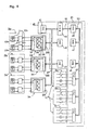
- a schematic control diagram for the control devices of the present embodiment includes robots 3a, 3b, and 3c but intentionally omits control devices for material supply device 5 and product removal device 6. Control devices for both material supply device 5 and product removal device 6 may be later included without interference with the present arrangement.
- Each robot 3a, 3b, and 3c is provided with a servo motor 31a and a servo motor 31b, as a means for driving or drive source for each corresponding robot in the above described x-axis(advance-retum) and z-axis (lift-lower) directions.
- Each servo motor 31a is provided with an encoder 33a and a servo amp 32a.
- Each server motor 31b is provided with an encoder 33b and a servo amp 32b.
- Encoders 33a, 33b may be of any type such as, mechanical, optical, acoustical, electromagnetic, or others as long as similar results are achieved.
- Servo amps 32a, 32b, for each robot 3a, 3b, and 3c are connected to a corresponding positioning controllers 34.
- Positioning controllers 34 output an operation command to corresponding servo amps 32a, 32b for each robot 3a, 3b, and 3c.
- respective servo motors 31a, 31b operate and, corresponding feed bars 11a, 11b of robots 3a, 3b, and 3c operate.
- Positioning controllers 34 are each constructed from an input-output (I/O) port 35, a central processing unit (CPU) 36, a read-only memory (ROM) 37, a random-access memory (RAM) 38, and a dual port RAM 39.
- I/O ports 35 are connected with servo amps 32a, 32b and receive positioning data from servo amps 32a, 32b and communicate positioning data back to servo amps 32a, 32b. In other words, the positioning data is sent back and fourth through I/O ports 35.
- a master board 40 includes a CPU 41, a ROM 42, a RAM 43, and a dual port RAM 44.
- a bus 51 is connected to and communicates to CPU 41, ROM 42, RAM 43, and dual port RAM 44.
- Bus 51 is connected to dual ports RAM 39 in programmable controllers 34. As a result, through bus 51, dual ports RAM 39, provided in each positioning controller 34, are connected to CPU 41, ROM 42, RAM 43, and dual port RAM 44.
- ROM 42 Programd into ROM 42 is an internal 360 degree clock 61(not shown) and a data output means (not shown).
- Internal clock 61(not shown) is equivalent to the movement speed of feed bars 11a, 11b of robots 3a, 3b, and 3c. The movement speed is also the motion speed or work transport speed of feed bars 11a, 11b of robots 3a, 3b, and 3c.
- internal clock 61 (not shown) times the movement of respective feed bars 11a, 11b and the data output means (not shown) outputs expansion data to each corresponding positioning controllers 34, according to internal clock 61, as will be explained.
- Master board 40 also includes a programmable controller 45.
- Programmable controller 45 includes a CPU 46, a ROM 47, a RAM 48, and an I/O port 49 for each robot 3a, 3b, and 3c.
- a bus 53 connects to CPU 46, ROM 47, RAM 48, and I/O ports 49.
- I/O ports 49 connect to a group of various devices 50 provided on each corresponding robot 3a, 3b, and 3c.
- Various devices 50 included standard electromagnetic valves, lamps, and other various equipment.
- a bus 52 connects CPU 46 with dual port RAM 44 of programmable controller 45.
- RAM 43 serves as a storage means. During press system 1 operation, expansion data, the pathway of the motion followed by robots 3a, 3b, and 3c during the above-described transport cycle, is plotted and saved in RAM 43. While RAM 43 serves as a primary storage means, other uses are not excluded including prior path histories or prior robot 3a, 3b, or 3c settings or controls.
- internal clock 61 which has been set to a predetermined speed of 60 spm in the present arrangement, outputs the angle for each position data point.
- a 2048 encoder 62 detects and encodes this output angle.
- the data output means outputs both the corresponding position data for each robot 3a, 3b, and 3c, and the angle detected by 2048 encoder 62, to each corresponding positioning controller 34.
- the position changes represented occur during the respective transport cycles of robots 3a, 3b, and 3c.
- a press encoder 63 is used when conducting linked operation with press machine 2a, 2b, or 2c.
- Linked operation occurs where internal clock 61 is replaced with a signal of encoder 63 that detects a crank angle of press machine 2a, 2b, or 2c.
- the positioning data is outputted according to a crank angle of the corresponding press machine 2a, 2b, or 2c.
- all robots 3a, 3b, and 3 operate synchronously with the press machine 2a, 2b, or 2c, similarly as during synchronous inching operation.
- robots 3a, 3b, and 3c may be operated simultaneously while avoiding interference with adjacent robots.
- the synchronous operation is not limited to this number.
- the number of synchronously operated press machines 2a, 2b, 2c or the number of robots 3a, 3b, 3c may be increased or decreased with minimal concern.
- robots 3a, 3b, or 3c may be continuously operated without need for a waiting time.
- expansion data comprising position data with which the pathway of robot movement is plotted, is saved in a storage means. Additionally, in accordance with an internal clock 61, equivalent to the work transport speed, the expansion data is outputted to a positioning controller by a data output means.
- a plurality of robots are continuously synchronized unlike the related art that required a matching a position of each robot at a midpoint. As a result, operation of robots is smoother and may be readily adapted to manufacturing requirements.
- a nail and screw may not be structural equivalents in that a nail relies entirely on friction between a wooden part and a cylindrical surface whereas a screw's helical surface positively engages the wooden part, in the environment of fastening wooden parts, a nail and a screw may be equivalent structures.
Landscapes
- Engineering & Computer Science (AREA)
- Physics & Mathematics (AREA)
- Mechanical Engineering (AREA)
- General Engineering & Computer Science (AREA)
- Manufacturing & Machinery (AREA)
- Quality & Reliability (AREA)
- Robotics (AREA)
- General Physics & Mathematics (AREA)
- Automation & Control Theory (AREA)
- Numerical Control (AREA)
- Manipulator (AREA)
- Control Of Position Or Direction (AREA)
- General Factory Administration (AREA)
Applications Claiming Priority (2)
| Application Number | Priority Date | Filing Date | Title |
|---|---|---|---|
| JP2000025392A JP2001212781A (ja) | 2000-02-02 | 2000-02-02 | ロボットの同期制御装置 |
| JP2000025392 | 2000-02-02 |
Publications (3)
| Publication Number | Publication Date |
|---|---|
| EP1122036A2 true EP1122036A2 (de) | 2001-08-08 |
| EP1122036A3 EP1122036A3 (de) | 2003-07-02 |
| EP1122036B1 EP1122036B1 (de) | 2011-01-05 |
Family
ID=18551254
Family Applications (1)
| Application Number | Title | Priority Date | Filing Date |
|---|---|---|---|
| EP01300823A Expired - Lifetime EP1122036B1 (de) | 2000-02-02 | 2001-01-30 | Vorrichtung zur synchronen Steuerung für Roboter |
Country Status (4)
| Country | Link |
|---|---|
| US (1) | US6401011B1 (de) |
| EP (1) | EP1122036B1 (de) |
| JP (1) | JP2001212781A (de) |
| DE (1) | DE60143777D1 (de) |
Cited By (4)
| Publication number | Priority date | Publication date | Assignee | Title |
|---|---|---|---|---|
| EP2110727A3 (de) * | 2008-04-16 | 2011-01-12 | KUKA Roboter GmbH | Verfahren zur Steuerung eines Roboters |
| CN107745382A (zh) * | 2017-09-29 | 2018-03-02 | 李少锋 | 机器手臂的同步控制系统 |
| CN110103232A (zh) * | 2019-03-14 | 2019-08-09 | 上海古鳌电子科技股份有限公司 | 一种银行用机器人 |
| CN110125244A (zh) * | 2018-02-08 | 2019-08-16 | 上海一芯智能科技有限公司 | 一种多冲压机械手联动控制方法、系统以及一种控制器 |
Families Citing this family (28)
| Publication number | Priority date | Publication date | Assignee | Title |
|---|---|---|---|---|
| DE602004019781D1 (de) * | 2003-06-20 | 2009-04-16 | Fanuc Robotics America Inc | Mehrfach-roboterarm-verfolgung und spiegel-jog |
| US7610119B2 (en) * | 2003-07-08 | 2009-10-27 | Omron Corporation | Safety controller and system using same |
| DE102005058867B4 (de) * | 2005-12-09 | 2018-09-27 | Cine-Tv Broadcast Systems Gmbh | Verfahren und Vorrichtung zum Bewegen einer auf einem Schwenk- und Neigekopf angeordneten Kamera entlang einer vorgegebenen Bewegungsbahn |
| ES2452022T3 (es) * | 2006-02-06 | 2014-03-31 | Abb Research Ltd. | Sistema de línea de prensas y método |
| WO2007141649A1 (en) * | 2006-06-06 | 2007-12-13 | Abb Research Ltd | Improved method and system for operating a cyclic production machine in coordination with a loader or unloader machine |
| JP5123050B2 (ja) * | 2008-05-21 | 2013-01-16 | ファナック株式会社 | ロボットおよびプレス機械を含むシステム、複数のロボットを含むシステム、ならびにそのようなシステムにおいて使用されるロボットの制御装置 |
| US8948906B2 (en) * | 2008-08-14 | 2015-02-03 | Spectra Logic Corporation | Robotic storage library with queued move instructions and method of queuing such instructions |
| US8457778B2 (en) * | 2008-08-15 | 2013-06-04 | Spectra Logic Corp. | Robotic storage library with queued move instructions and method of queuing such instructions |
| US8340810B2 (en) * | 2008-10-31 | 2012-12-25 | Spectra Logic Corp. | Robotic storage library with queued move instructions and method of queuing such instructions |
| US8666537B2 (en) * | 2008-10-31 | 2014-03-04 | Spectra Logic, Corporation | Robotic storage library with queued move instructions and method of queing such instructions |
| CN101740441B (zh) * | 2008-11-04 | 2012-04-11 | 北京北方微电子基地设备工艺研究中心有限责任公司 | 一种机械手调度方法、装置及等离子体处理设备 |
| US20100180711A1 (en) | 2009-01-19 | 2010-07-22 | Comau, Inc. | Robotic end effector system and method |
| EP2409457A4 (de) * | 2009-03-17 | 2012-12-19 | Comau Inc | Industriekommunikationssystem und -verfahren |
| WO2011088079A2 (en) * | 2010-01-12 | 2011-07-21 | Comau, Inc. | Distributed control system |
| CN101850548B (zh) * | 2010-04-16 | 2011-06-08 | 北京工业大学 | 一种基于飞轮的倒立摆平衡控制系统 |
| US8615322B2 (en) | 2010-09-27 | 2013-12-24 | Spectra Logic Corporation | Efficient moves via dual pickers |
| US8682471B2 (en) | 2010-09-27 | 2014-03-25 | Spectra Logic Corporation | Efficient magazine moves |
| JP5798410B2 (ja) * | 2011-08-19 | 2015-10-21 | 株式会社アイエイアイ | 中継器 |
| CN104379308B (zh) * | 2012-06-29 | 2016-05-18 | 三菱电机株式会社 | 机器人控制装置以及机器人控制方法 |
| CN102929191B (zh) * | 2012-10-18 | 2014-11-05 | 中达光电工业(吴江)有限公司 | 控制多个驱动器同步工作的方法及其装置 |
| WO2015058277A1 (en) | 2013-10-25 | 2015-04-30 | Transformix Engineering Inc. | Flexible feeding and closing machine for hinged caps |
| EP3012695B1 (de) | 2014-10-23 | 2017-10-11 | Comau S.p.A. | System zur Überwachung und Steuerung einer Industrieanlage |
| JP6026484B2 (ja) * | 2014-10-31 | 2016-11-16 | ファナック株式会社 | 工作機械の周辺機器の自立制御を可能とするシステム |
| CN105511400B (zh) * | 2016-02-04 | 2018-06-19 | 合肥泰禾光电科技股份有限公司 | 一种冲压机器人控制系统 |
| PL3366409T3 (pl) | 2017-02-23 | 2019-12-31 | Comau S.P.A. | Przegubowy robot przenoszący głowicę zgrzewająca do elektrycznego zgrzewania oporowego z elektrodami zlokalizowanymi po tej samej stronie; odpowiedni sposób zgrzewania elektrycznego oporowego komponentu do zgrzania |
| IT201800004086A1 (it) * | 2018-03-29 | 2019-09-29 | Fca Italy Spa | Procedimento per la messa in opera e/o la riconfigurazione di un impianto industriale, in particolare per la produzione di autoveicoli o loro sottogruppi |
| IT201800005091A1 (it) | 2018-05-04 | 2019-11-04 | "Procedimento per monitorare lo stato di funzionamento di una stazione di lavorazione, relativo sistema di monitoraggio e prodotto informatico" | |
| CN114310898B (zh) * | 2022-01-07 | 2022-09-06 | 深圳威洛博机器人有限公司 | 一种机器手同步控制系统及控制方法 |
Family Cites Families (12)
| Publication number | Priority date | Publication date | Assignee | Title |
|---|---|---|---|---|
| JPS5847190B2 (ja) * | 1975-10-17 | 1983-10-20 | 蛇の目ミシン工業株式会社 | デンシセイギヨミシン |
| JPS5317461A (en) * | 1976-07-30 | 1978-02-17 | Janome Sewing Machine Co Ltd | Electronic control sewing machine |
| US4815190A (en) * | 1987-08-20 | 1989-03-28 | Gmf Robotics Corporation | Method for automated assembly of assemblies such as automotive assemblies |
| US4894908A (en) * | 1987-08-20 | 1990-01-23 | Gmf Robotics Corporation | Method for automated assembly of assemblies such as automotive assemblies and system utilizing same |
| JPH0731532B2 (ja) * | 1989-05-24 | 1995-04-10 | オ−クマ株式会社 | 数値制御装置 |
| JPH0736993B2 (ja) * | 1989-07-27 | 1995-04-26 | 株式会社不二越 | 産業用ロボットシステム |
| JPH03204703A (ja) * | 1990-01-08 | 1991-09-06 | Mitsubishi Electric Corp | 数値制御装置 |
| JPH0553634A (ja) * | 1991-08-29 | 1993-03-05 | Matsushita Electric Ind Co Ltd | 複腕干渉回避システム |
| JP3282470B2 (ja) * | 1995-11-08 | 2002-05-13 | 三菱電機株式会社 | パソコンを用いた数値制御装置及びその制御方法 |
| JPH09275695A (ja) * | 1996-04-02 | 1997-10-21 | Minolta Co Ltd | モータ制御装置 |
| JPH103308A (ja) * | 1996-06-18 | 1998-01-06 | Fanuc Ltd | 産業用ロボットの干渉回避方法 |
| US5995884A (en) * | 1997-03-07 | 1999-11-30 | Allen; Timothy P. | Computer peripheral floor cleaning system and navigation method |
-
2000
- 2000-02-02 JP JP2000025392A patent/JP2001212781A/ja active Pending
- 2000-11-28 US US09/723,695 patent/US6401011B1/en not_active Expired - Lifetime
-
2001
- 2001-01-30 DE DE60143777T patent/DE60143777D1/de not_active Expired - Lifetime
- 2001-01-30 EP EP01300823A patent/EP1122036B1/de not_active Expired - Lifetime
Cited By (5)
| Publication number | Priority date | Publication date | Assignee | Title |
|---|---|---|---|---|
| EP2110727A3 (de) * | 2008-04-16 | 2011-01-12 | KUKA Roboter GmbH | Verfahren zur Steuerung eines Roboters |
| CN107745382A (zh) * | 2017-09-29 | 2018-03-02 | 李少锋 | 机器手臂的同步控制系统 |
| CN110125244A (zh) * | 2018-02-08 | 2019-08-16 | 上海一芯智能科技有限公司 | 一种多冲压机械手联动控制方法、系统以及一种控制器 |
| CN110125244B (zh) * | 2018-02-08 | 2020-08-14 | 上海一芯智能科技有限公司 | 一种多冲压机械手联动控制方法、系统以及一种控制器 |
| CN110103232A (zh) * | 2019-03-14 | 2019-08-09 | 上海古鳌电子科技股份有限公司 | 一种银行用机器人 |
Also Published As
| Publication number | Publication date |
|---|---|
| JP2001212781A (ja) | 2001-08-07 |
| DE60143777D1 (de) | 2011-02-17 |
| EP1122036A3 (de) | 2003-07-02 |
| EP1122036B1 (de) | 2011-01-05 |
| US6401011B1 (en) | 2002-06-04 |
Similar Documents
| Publication | Publication Date | Title |
|---|---|---|
| US6401011B1 (en) | Synchronous control device for robots | |
| CN1051061C (zh) | 形成玻璃容器的设备及独立单元 | |
| KR101168240B1 (ko) | 서보 프레스 설비 및 그 제어 방법 | |
| US20140148936A1 (en) | Computer numerical control assembly or processing of components | |
| CN101341451A (zh) | 包括工业机器人和接收来自机器人控制器的动作指令的机器的工业系统 | |
| KR20030060058A (ko) | 탠덤 프레스라인의 공작물반송방법 및 공작물반송장치 | |
| US4279561A (en) | Workpiece conveyor device for an automated press line | |
| WO2023094674A1 (en) | Method for forming a 3d object by an additive manufacturing machine with levitated print beds and corresponding additive manufacturing machine | |
| JPH0437424A (ja) | 機械ラインの操作を制御する装置及びその方法 | |
| WO2009096271A1 (ja) | サーボプレスラインとその制御方法 | |
| JP2009269081A (ja) | サーボプレス設備とその制御方法 | |
| CN112621390A (zh) | 一种多工序自动生产控制方法及多工序自动生产线 | |
| CN115255140B (zh) | 一种汽车零件精密高效加工混合模具及加工方法 | |
| CN107175268B (zh) | 一种新型数控多边折弯的多工位液压冲床 | |
| WO1997044149A1 (en) | Work feeder control apparatus | |
| JP3285209B2 (ja) | ワーク搬送ロボットの制御装置 | |
| JPH07119860A (ja) | 液圧方向制御装置及びこれを用いた液圧作動装置 | |
| KR100345256B1 (ko) | 단조프레스이송장치의위치제어방법 | |
| JP3194218B2 (ja) | トランスファフィーダ装置の同一軸の複数モータの単独操作方法及びその装置 | |
| JPH02224898A (ja) | パンチプレス機械 | |
| JPH0526210A (ja) | 分散処理制御装置 | |
| CN113771405B (zh) | 转移进给器装置及转移进给器装置的控制方法 | |
| CN215207263U (zh) | 一种基于机械臂的物料上下料装置 | |
| JPH1043825A (ja) | フィーダ装置の移動命令システム | |
| JP2597481B2 (ja) | マルチステーシヨンスイツチ装置 |
Legal Events
| Date | Code | Title | Description |
|---|---|---|---|
| PUAI | Public reference made under article 153(3) epc to a published international application that has entered the european phase |
Free format text: ORIGINAL CODE: 0009012 |
|
| AK | Designated contracting states |
Kind code of ref document: A2 Designated state(s): AT BE CH CY DE DK ES FI FR GB GR IE IT LI LU MC NL PT SE TR |
|
| AX | Request for extension of the european patent |
Free format text: AL;LT;LV;MK;RO;SI |
|
| RIC1 | Information provided on ipc code assigned before grant |
Free format text: 7B 25J 9/16 A, 7G 05B 19/418 B, 7G 05B 19/23 B |
|
| PUAL | Search report despatched |
Free format text: ORIGINAL CODE: 0009013 |
|
| AK | Designated contracting states |
Designated state(s): AT BE CH CY DE DK ES FI FR GB GR IE IT LI LU MC NL PT SE TR |
|
| AX | Request for extension of the european patent |
Extension state: AL LT LV MK RO SI |
|
| 17P | Request for examination filed |
Effective date: 20031219 |
|
| AKX | Designation fees paid |
Designated state(s): CH DE LI |
|
| RBV | Designated contracting states (corrected) |
Designated state(s): CH DE LI |
|
| 17Q | First examination report despatched |
Effective date: 20050324 |
|
| GRAP | Despatch of communication of intention to grant a patent |
Free format text: ORIGINAL CODE: EPIDOSNIGR1 |
|
| GRAS | Grant fee paid |
Free format text: ORIGINAL CODE: EPIDOSNIGR3 |
|
| GRAA | (expected) grant |
Free format text: ORIGINAL CODE: 0009210 |
|
| AK | Designated contracting states |
Kind code of ref document: B1 Designated state(s): CH DE LI |
|
| REG | Reference to a national code |
Ref country code: CH Ref legal event code: EP |
|
| REF | Corresponds to: |
Ref document number: 60143777 Country of ref document: DE Date of ref document: 20110217 Kind code of ref document: P |
|
| REG | Reference to a national code |
Ref country code: DE Ref legal event code: R096 Ref document number: 60143777 Country of ref document: DE Effective date: 20110217 |
|
| REG | Reference to a national code |
Ref country code: CH Ref legal event code: PL |
|
| PG25 | Lapsed in a contracting state [announced via postgrant information from national office to epo] |
Ref country code: LI Free format text: LAPSE BECAUSE OF NON-PAYMENT OF DUE FEES Effective date: 20110131 Ref country code: CH Free format text: LAPSE BECAUSE OF NON-PAYMENT OF DUE FEES Effective date: 20110131 |
|
| PLBE | No opposition filed within time limit |
Free format text: ORIGINAL CODE: 0009261 |
|
| STAA | Information on the status of an ep patent application or granted ep patent |
Free format text: STATUS: NO OPPOSITION FILED WITHIN TIME LIMIT |
|
| 26N | No opposition filed |
Effective date: 20111006 |
|
| REG | Reference to a national code |
Ref country code: DE Ref legal event code: R097 Ref document number: 60143777 Country of ref document: DE Effective date: 20111006 |
|
| PGFP | Annual fee paid to national office [announced via postgrant information from national office to epo] |
Ref country code: DE Payment date: 20170125 Year of fee payment: 17 |
|
| REG | Reference to a national code |
Ref country code: DE Ref legal event code: R119 Ref document number: 60143777 Country of ref document: DE |
|
| PG25 | Lapsed in a contracting state [announced via postgrant information from national office to epo] |
Ref country code: DE Free format text: LAPSE BECAUSE OF NON-PAYMENT OF DUE FEES Effective date: 20180801 |