EP1122093A2 - Ensemble roue de véhicule - Google Patents
Ensemble roue de véhicule Download PDFInfo
- Publication number
- EP1122093A2 EP1122093A2 EP01300451A EP01300451A EP1122093A2 EP 1122093 A2 EP1122093 A2 EP 1122093A2 EP 01300451 A EP01300451 A EP 01300451A EP 01300451 A EP01300451 A EP 01300451A EP 1122093 A2 EP1122093 A2 EP 1122093A2
- Authority
- EP
- European Patent Office
- Prior art keywords
- disc
- wheel assembly
- assembly
- narrow
- speed
- Prior art date
- Legal status (The legal status is an assumption and is not a legal conclusion. Google has not performed a legal analysis and makes no representation as to the accuracy of the status listed.)
- Withdrawn
Links
Images

Classifications
-
- B—PERFORMING OPERATIONS; TRANSPORTING
- B60—VEHICLES IN GENERAL
- B60B—VEHICLE WHEELS; CASTORS; AXLES FOR WHEELS OR CASTORS; INCREASING WHEEL ADHESION
- B60B11/00—Units comprising multiple wheels arranged side by side; Wheels having more than one rim or capable of carrying more than one tyre
-
- B—PERFORMING OPERATIONS; TRANSPORTING
- B66—HOISTING; LIFTING; HAULING
- B66F—HOISTING, LIFTING, HAULING OR PUSHING, NOT OTHERWISE PROVIDED FOR, e.g. DEVICES WHICH APPLY A LIFTING OR PUSHING FORCE DIRECTLY TO THE SURFACE OF A LOAD
- B66F9/00—Devices for lifting or lowering bulky or heavy goods for loading or unloading purposes
- B66F9/06—Devices for lifting or lowering bulky or heavy goods for loading or unloading purposes movable, with their loads, on wheels or the like, e.g. fork-lift trucks
- B66F9/075—Constructional features or details
- B66F9/07513—Details concerning the chassis
- B66F9/07518—Fuel or oil tank arrangements
Definitions
- This invention relates to a wheel assembly for a vehicle, and more specifically, the invention relates to a wheel assembly particularly useful for vehicles which frequently make tight turns.
- Axle assemblies having dual wheels on either end have been used to increase the load bearing capability of heavy duty vehicles.
- the pair of wheels on each end of the axle assembly are secured together so that they rotate together about an axis.
- a dual wheel assembly design has been proposed that uses hydraulic motors to independently drive each wheel.
- the design uses the operation of the suspension to reduce scrubbing and is not suitable for heavy vehicle applications.
- the hydraulic motors are not individually controlled so that the wheels cannot be rotatingly driven at different speeds relative to one another to travel along different radial distances and reduce scrubbing during vehicle turns. Therefore, what is needed is a wheel assembly with independently rotatable wheels that is also capable of reducing scrubbing across the width of each tire.
- the present invention provides a multi-disc wheel assembly for a vehicle that includes a plurality of narrow discs assemblies that form a wheel assembly.
- the plurality of narrow disc assemblies include first and second narrow disc assemblies.
- a first independent drive mechanism applies a rotational force to the first narrow disc assembly to produce a first speed.
- a second independent drive mechanism applies a rotational force to the second narrow disc assembly to produce a second speed unequal to the first speed during a vehicle turn to minimize wheel assembly scrub.
- the above invention provides a wheel assembly with independently rotatable wheels that is also capable of reducing scrubbing across the width of each tire.
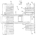
- a multi-disc wheel assembly 10 for a vehicle 12, such as a heavy lift truck, is shown in Figure 1.
- Heavy lift trucks 12, like the one shown, have a lift mechanism 13 and are used for lifting very heavy loads, such as a sea container 14.
- Heavy lift trucks 10 typically have a rather wide wheel base with wide, non-steerable front wheels for supporting the load on a road surface 16.
- the multi-disc wheel assemblies 10 of the present invention are an improvement over conventional wheel assemblies, which experience a significant amount of tire wear due to scrub.
- the wheel assembly 10 has a width that is approximately equal to a conventional wheel assembly width for a heavy lift truck. It should be appreciated that the present invention wheel assembly 10 may be suitable for any vehicle application having wide tires that undergo a significant amount of turning.
- the vehicle 10 has an axle assembly 18 with opposing ends 20 that may support multiple wheel assemblies 10 depending upon the load requirements of the particular vehicle.
- the axle assembly 18 may be one unitary structure or two separate stub axles.
- the axle assembly 18 has at least one wheel assembly 10 supported on each of the ends 20.
- a plurality of narrow discs assemblies 22 form each wheel assembly 10.
- the wheel assemblies 10 shown in Figure 1 each include a first 22a and second 22b narrow disc assemblies.
- a wheel assembly 10 is shown having first 22a, second 22b, third 22c, and fourth 22d narrow disc assemblies supported on an axle 18.
- the second narrow disc assembly 22b is interposed between the first 22a and third 22c narrow disc assemblies
- the third narrow disc assembly 22c is interposed between the second 22b and fourth 22d narrow disc assemblies.
- the four narrow disc assemblies together are approximately the width of a conventional wheel. It is to be understood that any number of narrow disc assemblies 22 may be used.
- Each disc assembly 22 has an independent drive mechanism 26, preferably an electric motor and even more preferably an induction motor, for driving the disc assemblies 22 at slightly different speeds during a vehicle turn to reduce scrub.
- the induction motors 26 are also used as the primary drive mechanisms for the vehicle.
- the induction motors 26 have a stator 28 and a rotor 30 that has a rim 32 with a tire 34.
- An internal combustion engine may generate the electric power needed for the induction motors.
- Each rim 32 and tire is driven by its respective independent drive mechanism 26 so that different speeds may be obtained. Scrubbing across the width of each tire 34 is reduced compared to a conventional wheel and tire because the present invention tires 34 are narrower. Scrubbing is further reduced by independently driving each tire 34 at the speed needed to travel the distance along its radial path.
- the vehicle turn has an inner R i and outer R o radius, and the first 22a and fourth 22d narrow disc assemblies are arranged at the inner R i and outer R o radii, respectively.
- the second 22b and third 22c narrow disc assemblies also have a turning radius, which is not shown for clarity.
- the independent drive mechanisms 26 for each narrow disc assembly 22a, 22b, 22c, 22d apply a rotational force to is respective narrow disc assembly to produce first, second, third, and fourth speeds, respectively.
- the second speed is greater than the first speed
- the third speed is greater than the second speed
- the fourth speed is greater than the third speed for the vehicle turn, shown in Figure 2.
- each narrow disc assembly 22 may rotate at the speed needed to travel the distance along its radial path so that tire wear from scrubbing is reduced.
- the multi-disc wheel assembly 10 may also include a controller 38 connected to the induction motors 26 and a sensor 40 connected to the controller 38 for sensing a vehicle turning radius.
- the sensor 40 sends a turning radius signal 42 to the controller 38 and the controller 38 produces a speed request signal 44 to the induction motors 26 for producing the desired speeds for each narrow disc assembly 22.
- the sensor 40 may measure the vehicle turning radius at a steering input device, or in any other suitable manner.
Landscapes
- Engineering & Computer Science (AREA)
- Transportation (AREA)
- Structural Engineering (AREA)
- Mechanical Engineering (AREA)
- Civil Engineering (AREA)
- Life Sciences & Earth Sciences (AREA)
- Geology (AREA)
- Arrangement Or Mounting Of Propulsion Units For Vehicles (AREA)
- Friction Gearing (AREA)
Applications Claiming Priority (2)
| Application Number | Priority Date | Filing Date | Title |
|---|---|---|---|
| US498404 | 1995-07-05 | ||
| US09/498,404 US6298932B1 (en) | 2000-02-04 | 2000-02-04 | Wheel assembly for a vehicle |
Publications (2)
| Publication Number | Publication Date |
|---|---|
| EP1122093A2 true EP1122093A2 (fr) | 2001-08-08 |
| EP1122093A3 EP1122093A3 (fr) | 2003-05-28 |
Family
ID=23980946
Family Applications (1)
| Application Number | Title | Priority Date | Filing Date |
|---|---|---|---|
| EP01300451A Withdrawn EP1122093A3 (fr) | 2000-02-04 | 2001-01-19 | Ensemble roue de véhicule |
Country Status (2)
| Country | Link |
|---|---|
| US (1) | US6298932B1 (fr) |
| EP (1) | EP1122093A3 (fr) |
Cited By (1)
| Publication number | Priority date | Publication date | Assignee | Title |
|---|---|---|---|---|
| FR2857648A1 (fr) * | 2003-07-17 | 2005-01-21 | Michelin Soc Tech | Vehicule lourd |
Families Citing this family (29)
| Publication number | Priority date | Publication date | Assignee | Title |
|---|---|---|---|---|
| US6757597B2 (en) | 2001-01-31 | 2004-06-29 | Oshkosh Truck | A/C bus assembly for electronic traction vehicle |
| US7729831B2 (en) | 1999-07-30 | 2010-06-01 | Oshkosh Corporation | Concrete placement vehicle control system and method |
| US7277782B2 (en) | 2001-01-31 | 2007-10-02 | Oshkosh Truck Corporation | Control system and method for electric vehicle |
| US7379797B2 (en) | 2001-01-31 | 2008-05-27 | Oshkosh Truck Corporation | System and method for braking in an electric vehicle |
| US6672985B2 (en) | 2001-08-30 | 2004-01-06 | Axletech International Ip Holdings, Llc | Independently rotating wheels with planetary drive |
| US7302320B2 (en) | 2001-12-21 | 2007-11-27 | Oshkosh Truck Corporation | Failure mode operation for an electric vehicle |
| US7254468B2 (en) | 2001-12-21 | 2007-08-07 | Oshkosh Truck Corporation | Multi-network control system for a vehicle |
| US6890039B2 (en) | 2002-03-06 | 2005-05-10 | Axletech International Ip Holdings, Llc | Independently rotating wheels |
| US7520354B2 (en) * | 2002-05-02 | 2009-04-21 | Oshkosh Truck Corporation | Hybrid vehicle with combustion engine/electric motor drive |
| US7439711B2 (en) | 2004-09-27 | 2008-10-21 | Oshkosh Corporation | Energy storage device including a status indicator |
| US8947531B2 (en) | 2006-06-19 | 2015-02-03 | Oshkosh Corporation | Vehicle diagnostics based on information communicated between vehicles |
| US8139109B2 (en) | 2006-06-19 | 2012-03-20 | Oshkosh Corporation | Vision system for an autonomous vehicle |
| US7757795B2 (en) | 2007-06-22 | 2010-07-20 | Axletech International Ip Holdings, Llc | Dual wheelend for a vehicle |
| EP2759459A1 (fr) | 2009-02-27 | 2014-07-30 | NACCO Materials Handling Group, Inc. | Essieu d'entraînement à inversion de puissance directe |
| US8596156B2 (en) | 2009-02-27 | 2013-12-03 | Robert David Clark | Vehicle transmission with clutch pack overrun |
| US8337352B2 (en) | 2010-06-22 | 2012-12-25 | Oshkosh Corporation | Electromechanical variable transmission |
| US9132736B1 (en) | 2013-03-14 | 2015-09-15 | Oshkosh Defense, Llc | Methods, systems, and vehicles with electromechanical variable transmission |
| US10005352B2 (en) * | 2014-09-15 | 2018-06-26 | Ford Global Technologies, Llc | Electrical bicycle modular powertrain |
| US10421350B2 (en) | 2015-10-20 | 2019-09-24 | Oshkosh Corporation | Inline electromechanical variable transmission system |
| US9650032B2 (en) | 2015-02-17 | 2017-05-16 | Oshkosh Corporation | Multi-mode electromechanical variable transmission |
| US9651120B2 (en) | 2015-02-17 | 2017-05-16 | Oshkosh Corporation | Multi-mode electromechanical variable transmission |
| US10584775B2 (en) | 2015-02-17 | 2020-03-10 | Oshkosh Corporation | Inline electromechanical variable transmission system |
| US10982736B2 (en) | 2015-02-17 | 2021-04-20 | Oshkosh Corporation | Multi-mode electromechanical variable transmission |
| US9656659B2 (en) | 2015-02-17 | 2017-05-23 | Oshkosh Corporation | Multi-mode electromechanical variable transmission |
| US10578195B2 (en) | 2015-02-17 | 2020-03-03 | Oshkosh Corporation | Inline electromechanical variable transmission system |
| US12078231B2 (en) | 2015-02-17 | 2024-09-03 | Oshkosh Corporation | Inline electromechanical variable transmission system |
| US11701959B2 (en) | 2015-02-17 | 2023-07-18 | Oshkosh Corporation | Inline electromechanical variable transmission system |
| US11390163B2 (en) * | 2019-08-27 | 2022-07-19 | Toyota Motor Engineering & Manufacturing North America, Inc. | Variable wheel drive electric vehicle comprising selectively attachable and detachable electric hub motors and method of using the same |
| US11446960B2 (en) * | 2019-08-27 | 2022-09-20 | Toyota Motor Engineering & Manufacturing North America, Inc. | Modular axle and motive wheel system for a vehicle |
Family Cites Families (8)
| Publication number | Priority date | Publication date | Assignee | Title |
|---|---|---|---|---|
| US2353730A (en) | 1942-04-08 | 1944-07-18 | Joseph F Joy | Wheel motor |
| US2748879A (en) | 1953-09-08 | 1956-06-05 | Fenton Max Macmillan | Fully oscillating vehicular suspension and/or drive |
| CA1279582C (fr) * | 1986-01-29 | 1991-01-29 | Katsuhiko Iijima | Entrainement electrique de roues |
| IL84382A (en) * | 1987-11-05 | 1995-12-08 | Carcom Computerized Vehicle Lt | Computerized electrical vehicle |
| DE3811398A1 (de) * | 1987-11-26 | 1989-10-26 | Geggerle Sigmund | Differentialausgleich von zwilling- bzw. mehrlingsraedern auf der selben achsseite einer antriebsachse mit hilfe eines geteilten rades, dessen teile zueinander elektromotorisch bewegt werden |
| US5258912A (en) * | 1991-06-24 | 1993-11-02 | General Motors Corporation | Wheel understeer speed control |
| KR0145431B1 (ko) * | 1992-10-14 | 1998-08-01 | 마스다 쇼오이치로오 | 이동차의 차바퀴 지지장치, 이것을 구비한 이동차 및 이 이동차를 가지는 물품 반송 시스템 |
| US5894902A (en) * | 1996-09-05 | 1999-04-20 | The United States Of America As Represented By The Secretary Of The Navy | Self-propelled wheel for wheeled vehicles |
-
2000
- 2000-02-04 US US09/498,404 patent/US6298932B1/en not_active Expired - Fee Related
-
2001
- 2001-01-19 EP EP01300451A patent/EP1122093A3/fr not_active Withdrawn
Non-Patent Citations (1)
| Title |
|---|
| None |
Cited By (3)
| Publication number | Priority date | Publication date | Assignee | Title |
|---|---|---|---|---|
| FR2857648A1 (fr) * | 2003-07-17 | 2005-01-21 | Michelin Soc Tech | Vehicule lourd |
| WO2005016731A1 (fr) * | 2003-07-17 | 2005-02-24 | Societe De Technologie Michelin | Vehicule lourd |
| US7987932B2 (en) | 2003-07-17 | 2011-08-02 | Michelin Recherche Et Technique S.A. | Heavy vehicle |
Also Published As
| Publication number | Publication date |
|---|---|
| US6298932B1 (en) | 2001-10-09 |
| EP1122093A3 (fr) | 2003-05-28 |
Similar Documents
| Publication | Publication Date | Title |
|---|---|---|
| US6298932B1 (en) | Wheel assembly for a vehicle | |
| JP3515628B2 (ja) | 電気自動車の駆動機構 | |
| US20140117746A1 (en) | Multi-diameter tire and wheel assembly for improved vehicle mileage with passive transfer between tire diameters | |
| EP1288054B1 (fr) | Dispositif d'éxtrémité de roue | |
| EP1342591B1 (fr) | Roues indépendantes en rotation | |
| EP2414213B1 (fr) | Véhicule orientable et procédé pour commander celui-ci | |
| US6254193B1 (en) | Dual wheel assembly differential | |
| JP4068697B2 (ja) | 駆動車軸 | |
| CN111409737A (zh) | 一种无转向系可全向移动的电动运载平台及其控制方法 | |
| US5941790A (en) | Drive axle assembly | |
| CN113335167B (zh) | 前轮组件以及重型车辆 | |
| US6345868B1 (en) | Fluid coupling for dual wheels | |
| EP1205335A2 (fr) | Mécanisme différentiel pour pneumatiques jumellés | |
| US6267188B1 (en) | Drive assembly for independently driving vehicle wheels | |
| JP3121193B2 (ja) | 複輪式駆動車軸装置 | |
| CN100548775C (zh) | 重型车辆 | |
| CN1822979B (zh) | 重型车辆 | |
| CN113879046B (zh) | 一种适用于全向车的转向车桥 | |
| CN223058786U (zh) | 车架 | |
| KR102831419B1 (ko) | 타이어 트레드부의 강성 보완 장치 | |
| US6135468A (en) | Front-wheel drive automobile having run-flat tires | |
| JP3351242B2 (ja) | 電動自動車の走行方法及び電動自動車 | |
| US20050236195A1 (en) | Telescopic loader, in particular a reach stacker | |
| WO2024239056A1 (fr) | Système d'entraînement différentiel à moteur pour une remorque électrique | |
| JPH106794A (ja) | ダブルタイヤを備える無軌道車両 |
Legal Events
| Date | Code | Title | Description |
|---|---|---|---|
| PUAI | Public reference made under article 153(3) epc to a published international application that has entered the european phase |
Free format text: ORIGINAL CODE: 0009012 |
|
| AK | Designated contracting states |
Kind code of ref document: A2 Designated state(s): AT BE CH CY DE DK ES FI FR GB GR IE IT LI LU MC NL PT SE TR |
|
| AX | Request for extension of the european patent |
Free format text: AL;LT;LV;MK;RO;SI |
|
| PUAL | Search report despatched |
Free format text: ORIGINAL CODE: 0009013 |
|
| AK | Designated contracting states |
Designated state(s): AT BE CH CY DE DK ES FI FR GB GR IE IT LI LU MC NL PT SE TR |
|
| AX | Request for extension of the european patent |
Extension state: AL LT LV MK RO SI |
|
| RIC1 | Information provided on ipc code assigned before grant |
Ipc: 7B 60K 7/00 B Ipc: 7B 66F 9/075 B Ipc: 7B 60B 11/00 A |
|
| AKX | Designation fees paid | ||
| REG | Reference to a national code |
Ref country code: DE Ref legal event code: 8566 |
|
| STAA | Information on the status of an ep patent application or granted ep patent |
Free format text: STATUS: THE APPLICATION IS DEEMED TO BE WITHDRAWN |
|
| 18D | Application deemed to be withdrawn |
Effective date: 20031129 |