EP1122128A2 - Passagierbeleuchtungssystem für ein öffentliches Transportfahrzeug - Google Patents
Passagierbeleuchtungssystem für ein öffentliches Transportfahrzeug Download PDFInfo
- Publication number
- EP1122128A2 EP1122128A2 EP01300915A EP01300915A EP1122128A2 EP 1122128 A2 EP1122128 A2 EP 1122128A2 EP 01300915 A EP01300915 A EP 01300915A EP 01300915 A EP01300915 A EP 01300915A EP 1122128 A2 EP1122128 A2 EP 1122128A2
- Authority
- EP
- European Patent Office
- Prior art keywords
- light
- vehicle
- housing
- lens
- emitting elements
- Prior art date
- Legal status (The legal status is an assumption and is not a legal conclusion. Google has not performed a legal analysis and makes no representation as to the accuracy of the status listed.)
- Withdrawn
Links
- 230000011664 signaling Effects 0.000 abstract description 4
- 239000000463 material Substances 0.000 description 6
- 229920002430 Fibre-reinforced plastic Polymers 0.000 description 3
- 229910052782 aluminium Inorganic materials 0.000 description 3
- XAGFODPZIPBFFR-UHFFFAOYSA-N aluminium Chemical compound [Al] XAGFODPZIPBFFR-UHFFFAOYSA-N 0.000 description 3
- 230000008878 coupling Effects 0.000 description 3
- 238000010168 coupling process Methods 0.000 description 3
- 238000005859 coupling reaction Methods 0.000 description 3
- 239000011151 fibre-reinforced plastic Substances 0.000 description 3
- 238000005286 illumination Methods 0.000 description 3
- 238000000034 method Methods 0.000 description 2
- 238000003825 pressing Methods 0.000 description 2
- 230000000630 rising effect Effects 0.000 description 2
- 239000000725 suspension Substances 0.000 description 2
- 238000004378 air conditioning Methods 0.000 description 1
- 239000004411 aluminium Substances 0.000 description 1
- 238000005452 bending Methods 0.000 description 1
- 230000005540 biological transmission Effects 0.000 description 1
- 230000006835 compression Effects 0.000 description 1
- 238000007906 compression Methods 0.000 description 1
- 230000001143 conditioned effect Effects 0.000 description 1
- 239000004020 conductor Substances 0.000 description 1
- 238000001816 cooling Methods 0.000 description 1
- 238000009792 diffusion process Methods 0.000 description 1
- 238000007599 discharging Methods 0.000 description 1
- 230000004313 glare Effects 0.000 description 1
- 238000010438 heat treatment Methods 0.000 description 1
- 238000009434 installation Methods 0.000 description 1
- 238000005304 joining Methods 0.000 description 1
- 238000004519 manufacturing process Methods 0.000 description 1
- 229910052751 metal Inorganic materials 0.000 description 1
- 239000002184 metal Substances 0.000 description 1
- 230000003287 optical effect Effects 0.000 description 1
- 239000004033 plastic Substances 0.000 description 1
- 229920003023 plastic Polymers 0.000 description 1
- 239000004417 polycarbonate Substances 0.000 description 1
- 229920000515 polycarbonate Polymers 0.000 description 1
- 239000000126 substance Substances 0.000 description 1
- 229920001169 thermoplastic Polymers 0.000 description 1
- 239000004416 thermosoftening plastic Substances 0.000 description 1
Images


Classifications
-
- B—PERFORMING OPERATIONS; TRANSPORTING
- B60—VEHICLES IN GENERAL
- B60N—SEATS SPECIALLY ADAPTED FOR VEHICLES; VEHICLE PASSENGER ACCOMMODATION NOT OTHERWISE PROVIDED FOR
- B60N3/00—Arrangements or adaptations of other passenger fittings, not otherwise provided for
- B60N3/02—Arrangements or adaptations of other passenger fittings, not otherwise provided for of hand grips or straps
- B60N3/026—Arrangements or adaptations of other passenger fittings, not otherwise provided for of hand grips or straps characterised by the fixing means
-
- B—PERFORMING OPERATIONS; TRANSPORTING
- B60—VEHICLES IN GENERAL
- B60N—SEATS SPECIALLY ADAPTED FOR VEHICLES; VEHICLE PASSENGER ACCOMMODATION NOT OTHERWISE PROVIDED FOR
- B60N3/00—Arrangements or adaptations of other passenger fittings, not otherwise provided for
- B60N3/02—Arrangements or adaptations of other passenger fittings, not otherwise provided for of hand grips or straps
-
- B—PERFORMING OPERATIONS; TRANSPORTING
- B60—VEHICLES IN GENERAL
- B60Q—ARRANGEMENT OF SIGNALLING OR LIGHTING DEVICES, THE MOUNTING OR SUPPORTING THEREOF OR CIRCUITS THEREFOR, FOR VEHICLES IN GENERAL
- B60Q3/00—Arrangement of lighting devices for vehicle interiors; Lighting devices specially adapted for vehicle interiors
- B60Q3/40—Arrangement of lighting devices for vehicle interiors; Lighting devices specially adapted for vehicle interiors specially adapted for specific vehicle types
- B60Q3/41—Arrangement of lighting devices for vehicle interiors; Lighting devices specially adapted for vehicle interiors specially adapted for specific vehicle types for mass transit vehicles, e.g. buses
- B60Q3/43—General lighting
-
- B—PERFORMING OPERATIONS; TRANSPORTING
- B60—VEHICLES IN GENERAL
- B60Q—ARRANGEMENT OF SIGNALLING OR LIGHTING DEVICES, THE MOUNTING OR SUPPORTING THEREOF OR CIRCUITS THEREFOR, FOR VEHICLES IN GENERAL
- B60Q2500/00—Special features or arrangements of vehicle interior lamps
- B60Q2500/20—Special features or arrangements of vehicle interior lamps associated with air conditioning arrangements
Definitions
- This invention relates to lighting system for a passenger area of a mass transit vehicle.
- Public transit vehicles particularly buses also including subway carriages generally provide a row of seats along each side of the vehicle and an aisle centrally of the vehicle.
- a lighting strip is positioned above the row of seats and generally there is an inclined advertising card receiving panel extending from the outside edge of the lighting downwardly toward the window.
- the lighting co-operates with or defines ductwork so as to communicate air conditioning to outlets adjacent to the top edge of the window for discharging downwardly onto the passengers in the row of seating.
- Transmatic Inc. of Michigan, U.S.A. is the leader in transit lighting systems and has over the years provided a number of different arrangements.
- Transmatic has recently introduced its new L20 Luminator lighting system.
- This system consists of a pultruded, crescent-shaped profile which forms the ad frame (into which slide the advertising placards) and also the support system for T12 fluorescent tubes, ballast, wiring, lens, and ventilator grilles, as well as forming the front wall of the heating and cooling system of the bus.
- the profile is connected along its top edge to the bus structure by means of a riveted, continuous hinge; captive fasteners along its bottom edge hold the profile in place. The entire assembly swings out for access to electrical components located in the space behind the lighting profile.
- a further feature which is necessary in transit vehicles is that of a signalling switch for actuation by the passenger to advise the driver of a desire to alight.
- the signalling switch is in the form of a cord dangled across the windows but more recent systems include a plurality of push buttons.
- Continuous strip switches are also known however these are not generally located in a suitable manner in conjunction with the lighting.
- a public transit vehicle comprising:
- the lens has first portions thereof which allow passage of the light therethrough and portions which are reflective to restrict passage of light therethrough to increase the amount of light passing through the first portions.
- an elongate advertising card support panel member supported in the vehicle body longitudinally of the vehicle at a position above the row of seats and having an upper edge adjacent to the light housing and inclined therefrom downwardly and toward an upper edge of the row of windows.
- the lens includes a generally flat substantially horizontal main body portion and an inclined portion which is inclined upwardly and outwardly along one edge adjacent the support panel for allowing light to fall onto the support panel.
- the opaque portions extend longitudinally of the lens and are arranged to restrict the passage of light directly from the light emitting elements toward the window and toward the aisle.
- the lens carries at least one upwardly projecting longitudinally extending fin on which is provided an opaque portion of the lens.
- the lens comprises a substantially horizontal portion which carries on an upper surface thereof two upwardly projecting longitudinally extending fins each on a respective side of the light emitting elements on each of which is provided an opaque portion of the lens and each of which is located between the light emitting elements and a respective one of the window and the aisle, the horizontal portion of the lens on either side of the fins and between the fins being arranged to allow the passage of reflected light from the reflector.
- one of the fins lying on the side adjacent the aisle is higher than that adjacent the window.
- the reflective portion extends from the respective fin partly onto the main body portion.
- the lens includes an integrally molded cylindrical hinge portion along one longitudinal edge which hinge portion is received in a cylindrical receptacle for rotation therein.
- an opposed longitudinal edge includes an upturned flange portion fastened to a flange portion of the housing by a plurality of spaced fasteners.
- the housing comprises a substantially longitudinally continuous channel defining the reflector for a plurality of the lighting elements, wherein each lighting element comprises a tube having electrical connectors at each end, wherein between each tube and the next is provided a web member having two sides lying in a plane at right angles to the axis and having an inner edge at right angles to the sides abutting a lower surface of the housing and an outer edge at right angles to the sides abutting an upper surface of the cover.
- the cover is divided into separate portions each having a length corresponding to that of a respective one of the tubes and the cover members have end portions thereof with the upper surface of the end portions lying in contact with the outer edge of respective ones of the web members.
- the reflector includes a V-shaped portion extending longitudinally thereof substantially at a center thereof above the light elements with an apex of the V-shaped portion projecting downwardly toward the element and two sides of the V-shaped portion diverging outwardly and connecting with the main body portion
- the sides merge contiguously with the main body portion.
- the V-shaped portion preferably carries at the apex a ground wire for the lighting element.
- a public transit vehicle comprising:
- a public transit vehicle comprising:
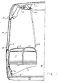
- a transit vehicle is shown in vertical cross section in Figure 1, 2 and 3 and in horizontal cross section in Figure 4.
- the only elements shown of the vehicle are those necessary to illustrate the present invention so that other elements such as the engine, transmission, wheels and suspension are omitted since these will vary widely and are well known to one skilled in the art.
- the transit vehicle 10 comprises a floor structure 11, a side wall 12 and a roof assembly 13 all of which include suitable panels and structural frame members which form the assembly into a rigid structure for mounting on suitable suspension.
- the details of the frame structure and the panels is not the subject of this invention and therefore will not be described in detail. Again these will be well known to one skilled in the art.
- the floor structure 11 includes a portion 14 underlying a row of passenger seats 15.
- the row of passenger seats is arranged in pairs of seats all facing forwardly while alternative arrangements for the seating can be used including seats facing rearwardly and seats at the side facing inwardly onto the aisle. In many cases a combination of such seats is used in the row of seats.
- the pair of seats includes a seat bottom 16 and seat back 17 which is formed into a rigid structural unit.
- One side of the seat is supported on a triangular cantilever 19 attached to the wall 12 just above an inclined panel portion 18 of the side wall.
- the cantilever 19 extends to an end 19A at the outer side of the seat.
- Hand grasping generally upright stanchions 20 extend from a bracket 20A at the ceiling. At least some of the seats include generally horizontal hand rail sections 21 for grasping by the passenger in seating or rising and these are connected to respective ones of the stanchions at a vertical collar 20B to allow the passenger to move the hand to the stanchion to assist further in rising and moving along an alleyway generally indicated at 22. Others of the stanchions (not shown) are free standing and extend to a bracket at the floor
- the side wall 12 includes a window 23 extending from an upper header 24 to a bottom sill 25.
- the lighting, advertising display, ducting and switching assembly for the vehicle is generally indicated at 26.
- This comprises a lamp housing 27 the details of which are best shown in Figure 3.
- the lamp housing is extruded from a suitable metal such as aluminum so as to provide the necessary reflective properties, to provide a ground plane to facilitate lamp starting and so as to provide structural strength to support itself and its components without vibrating or bending.
- the lamp housing 27 includes a generally parabolic reflector 28 extending from an outer end 29 adjacent to the window to an inner end 30 adjacent the aisle.
- the reflector is formed from two portions 28A and 28B which are joined at a coupling 28C.
- the portion 28A includes a pair of rearwardly and inwardly extending integrally formed rails 28D and 28E on the rear surface arranged to carry longitudinally spaced brackets 35 which support the sockets 36 for the fluorescent lamps 37.
- the rail 28E attaches to a rail 28F on the portion 28B at the coupling 28C by an interconnecting hook section and by a flange portion 28H at the bottom of the rail 28E.
- the fluorescent tubes 37 are arranged end to end, each having end fittings engaging into the sockets 36 at the axis 32.
- a generally planar web member 36A lying in a plane at right angles to the axis 32 and which is shaped with a top edge 36B following the shape of the reflector and abutting the lower surface thereof.
- a lower edge 36C opposite to the top edge and at right angles to the sides follows the shape of the lens 93 described hereinafter and abuts the upper surface of the lens.
- the lens is divided into panel portions of the same length as the tubes so that the upper surface of end portions of the lens panels abut onto the edge 36C of the web member 36A.
- each is associated with a square hole 39 which is cut at the back of the reflector.
- the web member is fastened in place in the reflector by screws 36D.
- the reflector portion 28 defines a downwardly facing reflective parabolic surface 31 defining axis of the parabola at 32.
- the parabolic surface is divided along its vertical plane containing the axis 32 by a V-shaped profile 32A the apex 32B of which projects toward the axis 32 to a position close to the axis but spaced from the axis sufficiently to leave room for the fluorescent tube.
- the apex 32B extends toward the focal point of the parabola.
- the surface 32C and 32D follows a V-shape defining sides joining smoothly or contiguously with the remaining surface of the parabola on either side of the V-shaped projection 32A.
- the V-shaped projection forms a beam splitter which is located at the apogee of the parabola and is bracketed by two large fillets or radii.
- the apex of the V-shape is thus centered over the axial center of the tube and it thus acts to divide light emitting vertically from the center and upper surface of the tube so that the light is not reflected by the otherwise parabolic surface of the reflector back into the tube. This reduces heat build up in the tube which otherwise would occur and substantially reduce the life of the tube.
- the reflector In an arrangement where the reflector is formed of aluminum or other conductive material, the reflector itself acts as a ground for the tube thus acting to assist in starting of the tube.
- the outer surface of the apex 32B defines a cylindrical surface which receives a ground wire 32H of the lighting system.
- the shape of the V-shaped projection locates the ground wire or the conductive body of the reflector within a distance of the order of 0.5 inches from the exterior of the tube and this distance is known to provide improved starting characteristics for the tube which reduces the voltage required at start up and thus prolongs the life of the tube.
- a horizontal flange portion 33 which extends outwardly toward the window.
- a cylindrical receptacle 34 is provided at the junction between the flange 33 and the edge 29.
- the inside rail 28E is attached to a fin 41 which extends vertically upwardly from that profile which is attached to a bulb seal 42 pressing against a roof bow 43.
- the fin is extruded with the lamp housing and therefore extends along the full length of the lamp housing and attaches into the bulb seal 42 which seals against the ceiling panel thus acting to divide the space between the ceiling and the lamp housing into a duct for conditioned or heated air.
- the flange 33 attaches to a structural member 33A carried on the roof bow 43.
- a receptacle portion 47 for the top of the stanchion 20.
- the receptacle portion 47 extends inwardly from the inner edge 30 and defines a series of generally horizontal plates 48, 49 and 50 which attach to a coupling 51 at the top of the stanchion 20.
- the plates converge into an outer portion 52 which forms a U-shaped loop with a downwardly extending nose 53 and an upturned and inwardly turned flange portion 54.
- a flange portion 55 matching the flange portion 52 and extending upwardly and inwardly to define an upper edge 56.
- the back plate 50 is connected by a bracket 57 to the roof bow 43.
- the structure 26 further includes a second member generally indicated at 60.
- This is best shown in Figure 2 and includes an advertising card support panel 61 connected at its upper end 62 to the receptacle 34.
- the upper end 62 has a cylindrical rib portion 63 which engages into and is directly attached to the receptacle 34 for rotation therein.
- a downturned lip 64 forming a receptacle for the upper edge of an advertising card (not shown).
- the panel 61 includes at a lower end 66 an upturned lip 67 to receive the bottom edge of the card (not shown).
- the panel 61 is curved so as to form a downwardly and inwardly concave surface so that the card when inserted into the lips 64 and 67 is pressed against the surface of the panel 61 and thus similarly concave.
- the member 60 includes a wall portion extending outwardly toward the window for connection to the wall structure above the window thus supporting the surface 73 and the switch band spaced inwardly from the wall at the window.
- Figure 6 is shown only the area at the bottom of the panel 61 where the band 73 is modified in shape to provide a recessed central area 73A for a press switch 74 in the form of an elongate band or strip for signalling the driver.
- the press switch strip is commercially available from various sources and one example of a source is Tape Switch Inc.
- the lamp housing is extruded from a material such as aluminium which provides structural strength.
- the body 60 can be pultruded from a fibre reinforced plastics material since it does not provide a structural element communicating significant forces but instead merely needs to be self-supporting to bridge the area between the edge of the lamp housing and the flange at the top of the window.
- the pultruded member 60 needs to have sufficient structural strength to support the advertising card, to accommodate the vibrations of the vehicle and to accommodate the compression forces by a passenger pressing on the switch element 74. Pultrusion is a well known system for manufacturing parts of continuous cross section.
- the lamp housing 27 and the member 60 can be formed thus in continuous lengths and cut to the required length which can be a single portion extending along the full length of the vehicle or could be formed into shorter sections for easier handling both in installation and in co-operation with the lamp sections which are generally four feet in length.
- the sections can be joined by suitable strip connectors to prevent the appearance of raw edges.
- the vehicle is of the type including a suspended ceiling panel 88 which covers an air duct and any other utilities supplied in this area. As shown in Figure 2, the suspended ceiling panel 88 has an upturned edge connection portion 89 and a down turned flange 90 which attaches over the lip 54.
- the lamp housing is covered by a lens/cover 93 which is formed from a clear extruded thermo-plastics material.
- the structure of the cover is best shown in Figure 3 and includes a hinge section 94 arranged at the outer edge of the lamp housing.
- the hinge section 94 defines a part cylindrical hinge member 95 which has an inner cylindrical surface co-operating with an outer cylindrical surface 96 of the lip 64..
- the hinge section 94 co-operates with the portions of the upper end 62 of the panel 61 to allow rotation about an axis along the center of the hinge section 94 thus causing the cover to open for access to the interior for service.
- the lens is divided into lengths approximately equal to that of the tubes so as to access each tube individually for service.
- Between the hinge section 94 and the main body of the lens is provided an inverted U-shaped portion 96A which projects upwardly from the edge of the hinge toward the edge of the reflector so as to avoid the appearance of an unsightly gap.
- the cover 93 includes an upturned flange portion 97 which co-operates with the flange portion 56 and is attached thereto by a plurality of spaced fasteners 98. These fasteners press the inner edge of a bottom panel 99 of the lens cover 93 against the horizontal bottom portion of the flange portion 55 to hold the lens cover firmly in place.
- the lens cover includes the substantially horizontal flat bottom panel 99, an upwardly and outwardly inclined section 100 and two fins 101 and 102 on the upper surface extending upwardly from and generally at right angles to the upper surface.
- the fins are spaced one on each side of the tube.
- the fin 101 is relatively short and does not project upwardly to the height of the tube.
- the fin 102 is higher so that its top edge is above that of the fin 101 and is approximately at the level of the axis 32.
- the lens cover includes a film 99A applied on the inside surface of the lens which has reflective portions 103 and 104 arranged on the inside surface of the fins 101 and 102, that is the surface facing the tube.
- the reflective portions 103 and 104 also extend from the respective fin onto a portion of the bottom wall 99 so that each reflective portion terminates at an inner edge 99B, 99C respectively.
- the film also provides an area 105 between the edges 99B and 99C and aligned with the tubes so that light from the tubes can pass through the area.
- the film in the area 105 is perforated or otherwise translucent so as to act to diffuse the light. Outside the fins, the lens is transparent so as to allow the light to pass directly through without diffusion.
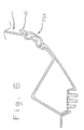
- the light patterns from the tube are shown in Figure 5.
- the fact that the tube is mounted at the center of the parabola of the mainly parabolic reflector ensures that light moving from the tube toward the reflector is reflected downwardly in parallel paths indicated generally at 106.
- the splitter defined by the V-shaped section causes the light to be reflected outwardly away from the tube and onto a further portion of the reflector to be reflected generally downwardly as indicated by one example beam 107.
- some light beams are emitted generally downwardly and outwardly directly from the tube, some light beams move onto the parabolic part of the reflector and thus are reflected directly downwardly and some light beams are reflected by the beam splitter and thus pass downwardly and outwardly from the lens after one or more reflections.
- the light from the tube or the reflector which is moving vertically downwardly can pass downwardly past the fins with little of the reflected light being intercepted by the reflective strips on the fins and on the bottom wall adjacent the fins.
- These areas of restricted light are indicated at 108 and 109.
- the reduction of light directed to the aisle reduces the glare to the passenger standing in the aisle and reduces light falling directly on the opposite window. This reduction in light emitted in these areas caused by the reflections thus increases the proportion of light emitted to the passenger sitting in the seat.
- the reduction of light to the windows reduces reflection from the window which can interfere with the passenger viewing through the window at night-time.
- the transparent inclined section 100 allows the light directly from the tube to fall onto the advertising card on the panel 61 for effective illumination thereof.
- An alternative technique for assisting in the direction of the light through the lens can be used in replacement for the fins or in addition to the fins so that light is primarily transmitted at right angles to the lens and the amount of light transmitted in the areas directed to the window and the aisle is reduced.
- This technique utilizes a product sold under the trademark LUMISTY, which trademark is the property of Sumitomo Chemical Co. Ltd. of Japan.
- This product is disclosed in a brochure supplied by Madico of Woburn MA. This product is believed to be described in United States Patent No: 5,108,857 of Sumitomo Chemical Company entitled "Light Control Sheets".
- the product comprises a sheet of plastics film which is applied onto one surface of the lens and acts to control the light passing through the lens.
- the sheet allows light which is incident upon the sheet at an angle approximately at right angles to the lens to pass in a straight line through the lens and through the sheet. Light that is incident at an angle to either side of the normal is scattered.
- the brochure provides three grades of the sheet material wherein the angle beyond the 15° from normal causes the light to be scattered.
- the sheet is thus applied to the interior surface of the extruded polycarbonate lens and extends from the reveal adjacent the part cylindrical hinge inwardly to the upturned end of the extruded lens which engages the stanchion channel. Its function is to orient the rays of light emanating directly from the tube vertically, prevent passengers from seeing the bulb from an angle, reduce the amount of light dispersed towards the windows and aisle, reduce the amount and harshness of the light generally emanating from the tube and to further orient light rays from the parabolic bulb reflector in a vertical stream.
- the covering further limits observation of the reflector and the socket and the socket support elements within the lighting channel.
Landscapes
- Engineering & Computer Science (AREA)
- Mechanical Engineering (AREA)
- Transportation (AREA)
- Arrangements Of Lighting Devices For Vehicle Interiors, Mounting And Supporting Thereof, Circuits Therefore (AREA)
Applications Claiming Priority (2)
| Application Number | Priority Date | Filing Date | Title |
|---|---|---|---|
| US497634 | 2000-02-03 | ||
| US09/497,634 US6350048B1 (en) | 2000-02-03 | 2000-02-03 | Passenger lighting system for mass transit vehicle |
Publications (2)
| Publication Number | Publication Date |
|---|---|
| EP1122128A2 true EP1122128A2 (de) | 2001-08-08 |
| EP1122128A3 EP1122128A3 (de) | 2002-08-21 |
Family
ID=23977655
Family Applications (1)
| Application Number | Title | Priority Date | Filing Date |
|---|---|---|---|
| EP01300915A Withdrawn EP1122128A3 (de) | 2000-02-03 | 2001-02-01 | Passagierbeleuchtungssystem für ein öffentliches Transportfahrzeug |
Country Status (2)
| Country | Link |
|---|---|
| US (1) | US6350048B1 (de) |
| EP (1) | EP1122128A3 (de) |
Cited By (3)
| Publication number | Priority date | Publication date | Assignee | Title |
|---|---|---|---|---|
| DE20310167U1 (de) | 2003-07-02 | 2003-10-09 | FER Fahrzeugelektrik GmbH, 99817 Eisenach | Fahrzeugleuchte mit einer Optik-Folie |
| FR2923169A1 (fr) * | 2007-11-06 | 2009-05-08 | Heuliez Bus Sa | Colonne pour vehicule de transport en commun et vehicule de transport en commun comprenant une telle colonne |
| WO2012064216A1 (ru) * | 2010-11-09 | 2012-05-18 | Открытое Акционерное Общество "Производственное Объединение "Уральский Оптико-Механический Завод" Имени Э.С. Яламова" (Оао "По "Уомз") | Осветительное устройство |
Families Citing this family (21)
| Publication number | Priority date | Publication date | Assignee | Title |
|---|---|---|---|---|
| US6502895B2 (en) * | 2001-02-23 | 2003-01-07 | International Truck Intellectual Property Company, L.L.C. | Unitized bus vehicle roof |
| WO2003078233A2 (en) * | 2002-03-15 | 2003-09-25 | Lamparter Ronald C | Modular system |
| US20040042225A1 (en) * | 2002-08-30 | 2004-03-04 | Dealey Onward K. | Vehicle interior lighting assembly |
| US7175320B1 (en) | 2002-09-20 | 2007-02-13 | Lynn Emerson Burgess | Adjustable elevated light for transportation vehicles |
| JP4163591B2 (ja) * | 2003-10-22 | 2008-10-08 | 矢崎総業株式会社 | 室内照明灯 |
| US8400061B2 (en) | 2007-07-17 | 2013-03-19 | I/O Controls Corporation | Control network for LED-based lighting system in a transit vehicle |
| US8210724B2 (en) * | 2008-03-24 | 2012-07-03 | I/O Controls Corporation | Low glare lighting for a transit vehicle |
| JP2012511231A (ja) * | 2008-12-05 | 2012-05-17 | コーニンクレッカ フィリップス エレクトロニクス エヌ ヴィ | 照明器具組み立て品 |
| US9162617B2 (en) | 2012-02-14 | 2015-10-20 | C&D Zodiac, Inc. | Pivot bin assembly |
| US9789963B2 (en) | 2012-02-14 | 2017-10-17 | C&D Zodiac, Inc. | Pivot bin assembly with minimal force required for closing |
| US9365291B2 (en) | 2012-02-14 | 2016-06-14 | C&D Zodiac, Inc. | Passenger service unit pod assembly |
| US8955805B2 (en) | 2012-02-14 | 2015-02-17 | C&D Zodiac, Inc. | Pivot bin assembly |
| US10029794B2 (en) | 2012-02-14 | 2018-07-24 | C&D Zodiac, Inc. | Outboard rotating pivot bin assembly |
| USD784905S1 (en) | 2013-02-12 | 2017-04-25 | C&D Zodiac, Inc. | Storage bin for aircraft |
| US9566890B2 (en) * | 2014-02-07 | 2017-02-14 | American Seating Company | Movable stanchion for transit buses |
| USD875641S1 (en) | 2015-02-02 | 2020-02-18 | C&D Zodiac, Inc. | Personal service unit |
| USD784904S1 (en) | 2015-02-02 | 2017-04-25 | C&D Zodiac, Inc. | Aircraft passenger service unit |
| US10214287B2 (en) * | 2016-02-26 | 2019-02-26 | The Boeing Company | Vehicle cabin wayfinding assembly |
| CN109606409B (zh) * | 2019-01-30 | 2024-02-02 | 重庆中车长客轨道车辆有限公司 | 一种车辆扶手安装结构和一种车辆 |
| CN109927604A (zh) * | 2019-03-15 | 2019-06-25 | 金龙联合汽车工业(苏州)有限公司 | 一种客车用车内顶扶手结构 |
| KR20230010319A (ko) * | 2021-07-12 | 2023-01-19 | 현대자동차주식회사 | 차량의 스탠션 파이프용 마운팅 장치 |
Citations (11)
| Publication number | Priority date | Publication date | Assignee | Title |
|---|---|---|---|---|
| US4387415A (en) | 1979-04-30 | 1983-06-07 | Transmatic, Inc. | Cornice lighting fixture |
| US4574336A (en) | 1984-03-27 | 1986-03-04 | Transmatic, Inc. | Cornice lighting fixture for mass transit vehicles |
| US4625267A (en) | 1984-09-28 | 1986-11-25 | Transmatic, Incorporated | Strip lighting fixture for mass transit vehicles |
| US5006966A (en) | 1989-08-30 | 1991-04-09 | Transmatic, Inc. | Transit vehicle lighting fixture |
| US5108857A (en) | 1986-12-18 | 1992-04-28 | Sumitomo Chemical Company, Limited | Light control sheets |
| US5113322A (en) | 1989-08-30 | 1992-05-12 | Transmatic, Inc. | Transit vehicle lighting fixture |
| US5441326A (en) | 1993-01-22 | 1995-08-15 | Transmatic, Inc. | Combined air conditioning duct, luggage compartment and lighting fixture for mass transit vehicles |
| US5678914A (en) | 1995-11-13 | 1997-10-21 | Transmatic, Inc. | Cargo area lighting system for trucks |
| US5752760A (en) | 1995-06-06 | 1998-05-19 | Transmatic, Inc. | Lighting system for mass-transit vehicles |
| US5857758A (en) | 1996-12-17 | 1999-01-12 | Transmatic, Inc. | Lighting system for mass-transit vehicles |
| US5860723A (en) | 1997-04-14 | 1999-01-19 | Transmatic, Inc. | Light engine with ellipsoidal reflector |
Family Cites Families (14)
| Publication number | Priority date | Publication date | Assignee | Title |
|---|---|---|---|---|
| US2262157A (en) | 1939-10-18 | 1941-11-11 | Miller Co | Enclosed direct lighting luminaire |
| US2587807A (en) * | 1947-07-25 | 1952-03-04 | Patent License Corp | Car lighting structure |
| US3210875A (en) * | 1963-02-05 | 1965-10-12 | Patent License Corp | Lighting fixture |
| DE1287031B (de) | 1964-06-25 | 1969-01-16 | Schmitt | Spiegelreflektoren fuer oberflaechenleuchtende Lichtquellen, insbesondere Leuchtstofflampen |
| US3233096A (en) | 1965-06-28 | 1966-02-01 | Schmitt Heinrich | Device for increasing the usable luminous flux of fluorescent lamps |
| US3748460A (en) | 1971-08-10 | 1973-07-24 | E Price | Recessed suspended lighting fixture |
| US3829677A (en) | 1972-11-07 | 1974-08-13 | Llano M De | Reflective means used in connection with fluorescent tubes or lamps |
| US4344111A (en) | 1977-12-20 | 1982-08-10 | Mcgraw-Edison Company | High efficiency lighting units and systems using same |
| EP0408709B1 (de) * | 1989-02-06 | 1993-06-09 | Deutsche Aerospace Airbus Gesellschaft mit beschränkter Haftung | Decken-gepäckablagen-kombination für die passagierkabine eines flugzeuges |
| US5394317A (en) | 1992-11-03 | 1995-02-28 | Grenga; John J. | Lamp reflector |
| FR2712376B1 (fr) * | 1993-11-09 | 1996-02-16 | Valeo Vision | Eclairage d'habitacle à tube fluorescent. |
| US5693921A (en) * | 1996-10-04 | 1997-12-02 | Miller Edge, Inc. | Continuous linear contact switch and method of assembling same |
| US6092913A (en) | 1998-03-26 | 2000-07-25 | Renova Technologies, Llc | Fluorescent light fixture |
| US6082879A (en) * | 1999-03-23 | 2000-07-04 | Myburgh; Herman | Combination light fixture/HVAC duct/advertising card holder for mass transit vehicles |
-
2000
- 2000-02-03 US US09/497,634 patent/US6350048B1/en not_active Expired - Fee Related
-
2001
- 2001-02-01 EP EP01300915A patent/EP1122128A3/de not_active Withdrawn
Patent Citations (12)
| Publication number | Priority date | Publication date | Assignee | Title |
|---|---|---|---|---|
| US4387415A (en) | 1979-04-30 | 1983-06-07 | Transmatic, Inc. | Cornice lighting fixture |
| US4387415B1 (de) | 1979-04-30 | 1992-12-01 | Transmatic Inc | |
| US4574336A (en) | 1984-03-27 | 1986-03-04 | Transmatic, Inc. | Cornice lighting fixture for mass transit vehicles |
| US4625267A (en) | 1984-09-28 | 1986-11-25 | Transmatic, Incorporated | Strip lighting fixture for mass transit vehicles |
| US5108857A (en) | 1986-12-18 | 1992-04-28 | Sumitomo Chemical Company, Limited | Light control sheets |
| US5006966A (en) | 1989-08-30 | 1991-04-09 | Transmatic, Inc. | Transit vehicle lighting fixture |
| US5113322A (en) | 1989-08-30 | 1992-05-12 | Transmatic, Inc. | Transit vehicle lighting fixture |
| US5441326A (en) | 1993-01-22 | 1995-08-15 | Transmatic, Inc. | Combined air conditioning duct, luggage compartment and lighting fixture for mass transit vehicles |
| US5752760A (en) | 1995-06-06 | 1998-05-19 | Transmatic, Inc. | Lighting system for mass-transit vehicles |
| US5678914A (en) | 1995-11-13 | 1997-10-21 | Transmatic, Inc. | Cargo area lighting system for trucks |
| US5857758A (en) | 1996-12-17 | 1999-01-12 | Transmatic, Inc. | Lighting system for mass-transit vehicles |
| US5860723A (en) | 1997-04-14 | 1999-01-19 | Transmatic, Inc. | Light engine with ellipsoidal reflector |
Cited By (3)
| Publication number | Priority date | Publication date | Assignee | Title |
|---|---|---|---|---|
| DE20310167U1 (de) | 2003-07-02 | 2003-10-09 | FER Fahrzeugelektrik GmbH, 99817 Eisenach | Fahrzeugleuchte mit einer Optik-Folie |
| FR2923169A1 (fr) * | 2007-11-06 | 2009-05-08 | Heuliez Bus Sa | Colonne pour vehicule de transport en commun et vehicule de transport en commun comprenant une telle colonne |
| WO2012064216A1 (ru) * | 2010-11-09 | 2012-05-18 | Открытое Акционерное Общество "Производственное Объединение "Уральский Оптико-Механический Завод" Имени Э.С. Яламова" (Оао "По "Уомз") | Осветительное устройство |
Also Published As
| Publication number | Publication date |
|---|---|
| US6350048B1 (en) | 2002-02-26 |
| EP1122128A3 (de) | 2002-08-21 |
Similar Documents
| Publication | Publication Date | Title |
|---|---|---|
| US6350048B1 (en) | Passenger lighting system for mass transit vehicle | |
| US6082879A (en) | Combination light fixture/HVAC duct/advertising card holder for mass transit vehicles | |
| US5441326A (en) | Combined air conditioning duct, luggage compartment and lighting fixture for mass transit vehicles | |
| US5857758A (en) | Lighting system for mass-transit vehicles | |
| US4574336A (en) | Cornice lighting fixture for mass transit vehicles | |
| US2587807A (en) | Car lighting structure | |
| NO862070L (no) | Avlang lysarmatur for kollektiv-transportkjoeretoeyer. | |
| US5752760A (en) | Lighting system for mass-transit vehicles | |
| JP5865797B2 (ja) | Led照明装置 | |
| US6827472B1 (en) | Illuminated HVAC duct/advertising card holder for vehicles | |
| US5006966A (en) | Transit vehicle lighting fixture | |
| US5113322A (en) | Transit vehicle lighting fixture | |
| US5595432A (en) | Lighting fixture | |
| CA2297875A1 (en) | Passenger lighting system for mass transit vehicle | |
| US2250954A (en) | Continuous lighting fixture | |
| US6510633B1 (en) | Panel illustration apparatus | |
| CN100500545C (zh) | 安装到电梯厢天花板的预制反光系统 | |
| CN210717168U (zh) | 一种型材灯 | |
| US2229203A (en) | Car lighting | |
| US2269795A (en) | Lighting arrangement for vehicles | |
| EP0981455B1 (de) | Montagevorrichtung für beleuchtung | |
| EP0859189A1 (de) | Beleuchtungseinrichtung mit Ventilationskanal | |
| NL1004903C2 (nl) | Autobus en binnenverlichting voor een autobus. | |
| JPH0579587U (ja) | 照明装置 | |
| HK1017319A (en) | Lighting system for mass-transit vehicles |
Legal Events
| Date | Code | Title | Description |
|---|---|---|---|
| PUAI | Public reference made under article 153(3) epc to a published international application that has entered the european phase |
Free format text: ORIGINAL CODE: 0009012 |
|
| AK | Designated contracting states |
Kind code of ref document: A2 Designated state(s): AT BE CH CY DE DK ES FI FR GB GR IE IT LI LU MC NL PT SE TR |
|
| AX | Request for extension of the european patent |
Free format text: AL;LT;LV;MK;RO;SI |
|
| PUAL | Search report despatched |
Free format text: ORIGINAL CODE: 0009013 |
|
| AK | Designated contracting states |
Kind code of ref document: A3 Designated state(s): AT BE CH CY DE DK ES FI FR GB GR IE IT LI LU MC NL PT SE TR |
|
| AX | Request for extension of the european patent |
Free format text: AL;LT;LV;MK;RO;SI |
|
| 17P | Request for examination filed |
Effective date: 20030218 |
|
| AKX | Designation fees paid |
Designated state(s): DE FR IT NL |
|
| RBV | Designated contracting states (corrected) |
Designated state(s): DE FR GB IT NL |
|
| STAA | Information on the status of an ep patent application or granted ep patent |
Free format text: STATUS: THE APPLICATION IS DEEMED TO BE WITHDRAWN |
|
| 18D | Application deemed to be withdrawn |
Effective date: 20060901 |