EP1122294B1 - Procédé et appareillage pour la pyrolyse de gas hydrocarboné - Google Patents
Procédé et appareillage pour la pyrolyse de gas hydrocarboné Download PDFInfo
- Publication number
- EP1122294B1 EP1122294B1 EP00104280A EP00104280A EP1122294B1 EP 1122294 B1 EP1122294 B1 EP 1122294B1 EP 00104280 A EP00104280 A EP 00104280A EP 00104280 A EP00104280 A EP 00104280A EP 1122294 B1 EP1122294 B1 EP 1122294B1
- Authority
- EP
- European Patent Office
- Prior art keywords
- hydrocarbon gas
- porous tubes
- gas
- porous
- reaction column
- Prior art date
- Legal status (The legal status is an assumption and is not a legal conclusion. Google has not performed a legal analysis and makes no representation as to the accuracy of the status listed.)
- Expired - Lifetime
Links
Images


Classifications
-
- C—CHEMISTRY; METALLURGY
- C10—PETROLEUM, GAS OR COKE INDUSTRIES; TECHNICAL GASES CONTAINING CARBON MONOXIDE; FUELS; LUBRICANTS; PEAT
- C10G—CRACKING HYDROCARBON OILS; PRODUCTION OF LIQUID HYDROCARBON MIXTURES, e.g. BY DESTRUCTIVE HYDROGENATION, OLIGOMERISATION, POLYMERISATION; RECOVERY OF HYDROCARBON OILS FROM OIL-SHALE, OIL-SAND, OR GASES; REFINING MIXTURES MAINLY CONSISTING OF HYDROCARBONS; REFORMING OF NAPHTHA; MINERAL WAXES
- C10G9/00—Thermal non-catalytic cracking, in the absence of hydrogen, of hydrocarbon oils
- C10G9/34—Thermal non-catalytic cracking, in the absence of hydrogen, of hydrocarbon oils by direct contact with inert preheated fluids, e.g. with molten metals or salts
- C10G9/36—Thermal non-catalytic cracking, in the absence of hydrogen, of hydrocarbon oils by direct contact with inert preheated fluids, e.g. with molten metals or salts with heated gases or vapours
- C10G9/38—Thermal non-catalytic cracking, in the absence of hydrogen, of hydrocarbon oils by direct contact with inert preheated fluids, e.g. with molten metals or salts with heated gases or vapours produced by partial combustion of the material to be cracked or by combustion of another hydrocarbon
-
- B—PERFORMING OPERATIONS; TRANSPORTING
- B01—PHYSICAL OR CHEMICAL PROCESSES OR APPARATUS IN GENERAL
- B01J—CHEMICAL OR PHYSICAL PROCESSES, e.g. CATALYSIS OR COLLOID CHEMISTRY; THEIR RELEVANT APPARATUS
- B01J12/00—Chemical processes in general for reacting gaseous media with gaseous media; Apparatus specially adapted therefor
- B01J12/005—Chemical processes in general for reacting gaseous media with gaseous media; Apparatus specially adapted therefor carried out at high temperatures, e.g. by pyrolysis
-
- B—PERFORMING OPERATIONS; TRANSPORTING
- B01—PHYSICAL OR CHEMICAL PROCESSES OR APPARATUS IN GENERAL
- B01J—CHEMICAL OR PHYSICAL PROCESSES, e.g. CATALYSIS OR COLLOID CHEMISTRY; THEIR RELEVANT APPARATUS
- B01J19/00—Chemical, physical or physico-chemical processes in general; Their relevant apparatus
- B01J19/24—Stationary reactors without moving elements inside
- B01J19/2415—Tubular reactors
- B01J19/2425—Tubular reactors in parallel
-
- B—PERFORMING OPERATIONS; TRANSPORTING
- B01—PHYSICAL OR CHEMICAL PROCESSES OR APPARATUS IN GENERAL
- B01J—CHEMICAL OR PHYSICAL PROCESSES, e.g. CATALYSIS OR COLLOID CHEMISTRY; THEIR RELEVANT APPARATUS
- B01J19/00—Chemical, physical or physico-chemical processes in general; Their relevant apparatus
- B01J19/24—Stationary reactors without moving elements inside
- B01J19/2475—Membrane reactors
-
- B—PERFORMING OPERATIONS; TRANSPORTING
- B01—PHYSICAL OR CHEMICAL PROCESSES OR APPARATUS IN GENERAL
- B01J—CHEMICAL OR PHYSICAL PROCESSES, e.g. CATALYSIS OR COLLOID CHEMISTRY; THEIR RELEVANT APPARATUS
- B01J4/00—Feed or outlet devices; Feed or outlet control devices
- B01J4/04—Feed or outlet devices; Feed or outlet control devices using osmotic pressure using membranes, porous plates
-
- C—CHEMISTRY; METALLURGY
- C01—INORGANIC CHEMISTRY
- C01B—NON-METALLIC ELEMENTS; COMPOUNDS THEREOF; METALLOIDS OR COMPOUNDS THEREOF NOT COVERED BY SUBCLASS C01C
- C01B3/00—Hydrogen; Gaseous mixtures containing hydrogen; Separation of hydrogen from mixtures containing it; Purification of hydrogen; Reversible storage of hydrogen
- C01B3/02—Production of hydrogen; Production of gaseous mixtures containing hydrogen
- C01B3/22—Production of hydrogen; Production of gaseous mixtures containing hydrogen by decomposition of gaseous or liquid organic compounds
- C01B3/24—Production of hydrogen; Production of gaseous mixtures containing hydrogen by decomposition of gaseous or liquid organic compounds of hydrocarbons
-
- C—CHEMISTRY; METALLURGY
- C01—INORGANIC CHEMISTRY
- C01B—NON-METALLIC ELEMENTS; COMPOUNDS THEREOF; METALLOIDS OR COMPOUNDS THEREOF NOT COVERED BY SUBCLASS C01C
- C01B3/00—Hydrogen; Gaseous mixtures containing hydrogen; Separation of hydrogen from mixtures containing it; Purification of hydrogen; Reversible storage of hydrogen
- C01B3/02—Production of hydrogen; Production of gaseous mixtures containing hydrogen
- C01B3/32—Production of hydrogen; Production of gaseous mixtures containing hydrogen by reaction of gaseous or liquid organic compounds with gasifying agents, e.g. water, carbon dioxide or air
- C01B3/34—Production of hydrogen; Production of gaseous mixtures containing hydrogen by reaction of gaseous or liquid organic compounds with gasifying agents, e.g. water, carbon dioxide or air by reaction of hydrocarbons with gasifying agents
-
- B—PERFORMING OPERATIONS; TRANSPORTING
- B01—PHYSICAL OR CHEMICAL PROCESSES OR APPARATUS IN GENERAL
- B01J—CHEMICAL OR PHYSICAL PROCESSES, e.g. CATALYSIS OR COLLOID CHEMISTRY; THEIR RELEVANT APPARATUS
- B01J2219/00—Chemical, physical or physico-chemical processes in general; Their relevant apparatus
- B01J2219/00049—Controlling or regulating processes
- B01J2219/00051—Controlling the temperature
- B01J2219/00121—Controlling the temperature by direct heating or cooling
- B01J2219/00123—Controlling the temperature by direct heating or cooling adding a temperature modifying medium to the reactants
-
- B—PERFORMING OPERATIONS; TRANSPORTING
- B01—PHYSICAL OR CHEMICAL PROCESSES OR APPARATUS IN GENERAL
- B01J—CHEMICAL OR PHYSICAL PROCESSES, e.g. CATALYSIS OR COLLOID CHEMISTRY; THEIR RELEVANT APPARATUS
- B01J2219/00—Chemical, physical or physico-chemical processes in general; Their relevant apparatus
- B01J2219/00049—Controlling or regulating processes
- B01J2219/00051—Controlling the temperature
- B01J2219/00157—Controlling the temperature by means of a burner
Definitions
- the present invention relates to an apparatus for pyrolyzing a hydrocarbon gas, optionally mixed with water vapor, to produce an olefin-based organic compound or a synthetic gas containing hydrogen or an olefin-based organic compound
- Said conventional apparatus comprises an elongated housing; means for introducing ethane; outlet means for discharging a reaction mixture; a plurality of porous tube reaction units; and means for introducing oxygen into said tubes.
- Said conventional apparatus is a multiple tube reactor wherein hydrocarbon feed is fed through an inlet port in the top of the reactor into an inlet plenum chamber connected to each tube. Oxygen is introduced in the shell of the reactor. The resultant product can exit via each tube. A cooling section is provided for cooling the reaction products.
- EP-A-607 862 discloses an apparatus for obtaining hydrocarbon oil from waste plastic material or waste rubber material.
- Said conventional apparatus comprises a thermal cracking portion for effecting thermal cracking of waste plastic material or waste rubber material for obtaining a thermal cracking product; a catalytic cracking portion in which the thermal cracking product is subjected to catalytic cracking to obtain a catalytic cracking product; a cooling portion for cooling the catalytic cracking product to obtain a first hydrocarbon oil; an oligomerization portion in which the cracking gas component is subjected to oligomerization by using polymerisation catalysts to obtain a second hydrocarbon oil; and a recovery portion for recovering the first and second hydrocarbon oils.
- An object of the invention is to provide an apparatus for the pyrolysis of a hydrocarbon gas which does not require high temperature heating and thus can be operated at reduced facility costs and undergoes less caulking.
- the inventive apparatus provides for rapidly cooling the pyrolyzed gas to reduce the equipment costs and to increase the yielding ratio of useful gas.
- the inventive apparatus comprises a decomposition reaction column having an inlet provided at one end thereof through which a hydrocarbon gas, optionally mixed with water vapor, may be supplied thereinto; an outlet provided at the other end thereof through which an olefin-based organic compound gas produced is dischargeable; a group of porous tubes extending vertically within said reaction column; a header connected to said porous tubes for supplying air or oxygen into said porous tubes; wherein said hydrocarbon gas, optionally mixed with water vapor is flown along the exterior of said porous tubes; and wherein said air or oxygen from the interior is homogenously jetted to the exterior of said porous tubes in a direction perpendicular to said stream of hydrocarbon gas, optionally mixed with water vapor, wherein an ignition system is provided for forming a diffusion flame layer on the outer surface of said porous tubes, said diffusion flame layer serving as a heat source required for allowing said hydrocarbon gas to undergo a radical reaction.
- a hydrocarbon gas to be decomposed, optionally mixed with water vapor is allowed to flow uniformly through the gap between various porous tubes constituting a group of porous tubes extending vertically in a decomposition reaction column. Air or oxygen is then homogeneously jetted from the interior to the exterior of the porous tubes in the direction perpendicular to a stream of the hydrocarbon gas to be decomposed, optionally mixed with water vapor.
- the hydrocarbon gas to be decomposed, optionally mixed with water vapor is then ignited to form a diffusion flame layer on the outer surface of the porous tubes.
- air or oxygen is allowed to flow uniformly through the gap between various porous tubes constituting a group of porous tubes extending vertically in a decomposition reaction column.
- a hydrocabon gas to be decomposed, optionally mixed water vapor is supplied into the porous tubes.
- Air or oxygen is then homogeneously jetted from the exterior to the interior of the porous tubes in the direction perpendicular to a stream of a hydrocarbon gas to be decomposed, optionally mixed with water vapor.
- the inventive apparatus is provided with a gas rapidly cooling device adjacent to the pyrolysis portion having the porous tubes.
- Fig. 1 is a diagram illustrating the concept of an apparatus for the pyrolysis of a hydrocarbon gas according to the first example of the invention.
- the reference numeral 1 indicates a decomposition reaction column comprising a diffuser 2 provided at the upper portion thereof and a reducer 3 provided at the lower portion thereof.
- a group of porous tubes Provided extending vertically in the decomposition reaction column 1 are a group of porous tubes.
- the reaction column may be cylindrical or prismatic.
- the various porous tubes constituting the foregoing group of porous tubes are each made of a porous metal or a metal film material having a pore size of the order of MF (microfiltration) or UF (ultrafiltration).
- a porous metal or metal film material there may be used SUS, tool steel, inconnel, titanium alloy, aluminum alloy or the like.
- the various porous tubes 4 are each blocked at the upper end thereof and connected to the header 5 at the lower end thereof.
- the header 5 is a hollow plate.
- non-porous tubes 7 which are connected to the foregoing porous tubes 4 with a joint 6, respectively.
- a distributor 8 Provided at the lower end of the diffuser 2 and above the group of porous tubes is a distributor 8. Provided in the gap between the outer surface of the upper portion of the various porous tubes 4 is an ignition system 9.
- the diffuser 2 is provided with an inlet 2a through which a hydrocarbon gas to be decomposed such as paraffin gas, optionally mixed with water vapor, is supplied into the decomposition reaction column 1.
- the reducer 3 is provided with an outlet 3a through which a gas such as olefinic gas obtained by decomposition and purification is discharged out of the decomposition reaction column 1.
- the header 5 is provided with a nozzle 5a through which air or oxygen is supplied into the decomposition reaction column 1.
- a hydrocarbon gas to be decomposed, optionally mixed with water vapor, is supplied into the decomposition reaction column 1 through the inlet 2a, rectified through the distributor, and then allowed to flow downward from the upper portion of the reaction column 1 uniformly through the gap between the various porous tubes 4.
- air or oxygen which has been supplied into the reaction column 1 through the supply nozzle 5a is then jetted homogeneously out of the porous tubes through the pores in the porous metal material in the direction perpendicular to the stream of the hydrocarbon gas to be decomposed, optionally mixed with water vapor, due to the difference in pressure between inside and outside the porous tubes.
- a diffusion flame layer B is then formed on the outer surface of the porous tubes 4 as shown in Fig. 2.
- the hydrocarbon gas to be decomposed such as paraffinic gas, optionally mixed with water vapor, undergoes radical reaction (free radical reaction) to produce a gaseous olefinic organic compound having a shorter chain chemical composition or a synthetic gas containing hydrogen, methane, carbon monoxide and a gaseous olefinic organic compound having a shorter chain chemical composition.
- Fig. 3 is a diagram illustrating the concept of an apparatus for the pyrolysis of a hydrocarbon gas according to the second example of the invention. Since the present example differs from the first example only in that non-porous tubes 10 are provided concentrically of the porous tubes 4 surrounding the periphery of the porous tubes 4, respectively, with a gap interposed therebetween, the description of other structures will be omitted. In some detail, as shown in Fig.
- air is allowed to flow through the inner tube of a double tube consisting of the porous tube 4 as an inner tube and the non-porous tube 10 as an outer tube while a hydrocarbon gas to be decomposed, optionally mixed with water vapor, is allowed the flow space (double tube portion) defined by the inner tube and the outer tube, whereby the hydrocarbon gas to be decomposed undergoes radical reaction as in the first example to produce a gaseous olefinic organic compound having a shorter chain chemical composition or a synthetic gas containing hydrogen, methane, carbon monoxide and a gaseous olefinic organic compound having a shorter chain chemical composition.
- air or oxygen is allowed to flow from the interior of the porous tubes 4 to the exterior of the porous tubes 4 while a hydrocarbon gas to be decomposed, optionally mixed water vapor, is allowed to flow along the exterior of the porous tubes 4.
- a hydrocarbon gas to be decomposed, optionally mixed with water vapor is allowed to flow the interior of the porous tubes 4 while air or oxygen may be allowed to flow from the exterior of the porous tube 4 to the interior of the porous tubes 4.
- a hydrocarbon gas to be decomposed is supplied into the decomposition reaction column 1.
- a gas produced by a process which comprises supplying a solid starting material such as waste plastic into a gasification apparatus 11 where it is then heated by a heating device 13 to decompose to a gas and a residue, and decomposed gas may be applied into the reaction column 1 through the inlet 2a.
- the decomposition reaction column 1 is provided with the inlet 2a at the upper portion thereof and the outlet 3a at the lower portion thereof.
- the decomposition reaction column 1 may be provided with the inlet 2a at the lower portion thereof and the outlet 3a at the upper portion thereof.
- Fig. 6 is a diagram illustrating the concept of an apparatus for the pyrolysis of a hydrocarbon gas according to the first example of the invention.
- an upper portion of reaction column is the same as the structure described in the first embodiment, and a lower portion corresponds to a gas rapidly cooling column 100 for the pyrolyzed gas produced in the upper portion.
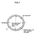
- Coolant spraying tubes 14 are arranged along with an inner peripheral portion of the gas rapidly cooling column 100.
- the pyrolyzed gas produced in the reaction column as shown in Fig. 6 is transferred directly from the reaction column to the gas rapidly cooling column 100.
- coolant sprays from a slit or a spraying hole provided on the coolant spray tubes 14 toward the gas flow path in such a manner that the coolant sprays slantly with respect to the center of a gas cooling portion to achieve a spiral air flow in the gas rapidly cooling portion as shown in Fig. 7.
- the coolant spray tubes 14 are arranged in the gas rapidly cooling column 100 to rapidly cool the gas produced in the upper portion of reaction column 1.
- the pyrolysis apparatus is characterized by allowing a hydrocarbon gas obtained by the evaporation of naphtha or the like, optionally mixed with water vapor, to come in direct contact with air or oxygen to form a diffusion flame layer, and then allowing the mixture to undergo radical reaction with the diffusion flame layer as a heat source.
- a desired olefin-based organic compound gas or a synthetic gas containing hydrogen, methane, carbon monoxide and an olefin-based organic compound gas having a short chain chemical composition can be produced without a high temperature and pressure process, making it possible to reduce the facility cost and avoid caulking.
- the reacted gas can be rapidly cooled to increase yield of the synthetic gas to be desired.
Landscapes
- Chemical & Material Sciences (AREA)
- Organic Chemistry (AREA)
- Chemical Kinetics & Catalysis (AREA)
- Engineering & Computer Science (AREA)
- Combustion & Propulsion (AREA)
- Oil, Petroleum & Natural Gas (AREA)
- Health & Medical Sciences (AREA)
- General Health & Medical Sciences (AREA)
- Inorganic Chemistry (AREA)
- Physics & Mathematics (AREA)
- General Chemical & Material Sciences (AREA)
- Thermal Sciences (AREA)
- Organic Low-Molecular-Weight Compounds And Preparation Thereof (AREA)
- Production Of Liquid Hydrocarbon Mixture For Refining Petroleum (AREA)
- Separation, Recovery Or Treatment Of Waste Materials Containing Plastics (AREA)
- Hydrogen, Water And Hydrids (AREA)
Claims (4)
- Appareil servant à pyrolyser un hydrocarbure gazeux comprenant :dans lequel on fait circuler ledit hydrocarbure gazeux, facultativement mélangé avec de la vapeur d'eau, le long de l'extérieur desdits tubes poreux (4) ; etune colonne de réaction de décomposition (1) ayant une entrée pourvue à une extrémité de celle-ci par laquelle on peut introduire dans celle-ci un hydrocarbure gazeux, facultativement mélangé avec de la vapeur d'eau ;une sortie pourvue à l'autre extrémité de celle-ci par laquelle on peut décharger un composé organique gazeux à base d'oléfine produit ;un groupe de tubes poreux (4) placés verticalement à l'intérieur de ladite colonne de réaction ;un collecteur relié aux dits tubes poreux servant à introduire de l'air ou de l'oxygène dans lesdits tubes poreux ;
dans lequel de l'air ou de l'oxygène provenant de l'intérieur est injecté de façon homogène vers l'extérieur desdits tubes poreux (4) dans une direction perpendiculaire au dit flux d'hydrocarbure gazeux, facultativement mélangé avec de la vapeur d'eau, dans lequel un système d'allumage (9) est pourvu pour former une couche de flammes de diffusion (B) sur la surface externe desdits tubes poreux (4), ladite couche de flammes de diffusion servant de source de chaleur requise pour permettre au dit hydrocarbure gazeux de subir une réaction radicalaire. - Appareil servant à pyrolyser un hydrocarbure gazeux selon la revendication 1, dans lequel un tube non poreux (7) est pourvu de façon concentrique par rapport aux dits tubes poreux (4) en entourant la périphérie desdits tubes poreux.
- Appareil servant à pyrolyser un hydrocarbure gazeux selon la revendication 1 ou 2, dans lequel un distributeur (8) est pourvu du côté de l'entrée de ladite colonne de réaction de décomposition (1).
- Appareil servant à pyrolyser un hydrocarbure gazeux selon les revendications 1, 2 ou 3, comprenant en plus:une partie de refroidissement des gaz (100) directement reliée à ladite colonne de réaction de décomposition (1).
Applications Claiming Priority (2)
| Application Number | Priority Date | Filing Date | Title |
|---|---|---|---|
| JP2000025251A JP2001220102A (ja) | 2000-02-02 | 2000-02-02 | 合成ガスの生成方法およびその装置 |
| JP2000025251 | 2000-02-02 |
Publications (3)
| Publication Number | Publication Date |
|---|---|
| EP1122294A2 EP1122294A2 (fr) | 2001-08-08 |
| EP1122294A3 EP1122294A3 (fr) | 2002-03-06 |
| EP1122294B1 true EP1122294B1 (fr) | 2004-11-24 |
Family
ID=18551137
Family Applications (1)
| Application Number | Title | Priority Date | Filing Date |
|---|---|---|---|
| EP00104280A Expired - Lifetime EP1122294B1 (fr) | 2000-02-02 | 2000-03-01 | Procédé et appareillage pour la pyrolyse de gas hydrocarboné |
Country Status (4)
| Country | Link |
|---|---|
| US (1) | US6921517B2 (fr) |
| EP (1) | EP1122294B1 (fr) |
| JP (1) | JP2001220102A (fr) |
| DE (1) | DE60016159T2 (fr) |
Families Citing this family (12)
| Publication number | Priority date | Publication date | Assignee | Title |
|---|---|---|---|---|
| KR100440479B1 (ko) * | 2002-04-23 | 2004-07-14 | 주식회사 엘지화학 | 탄화수소의 열분해 공정 |
| US7344622B2 (en) * | 2003-04-08 | 2008-03-18 | Grispin Charles W | Pyrolytic process and apparatus for producing enhanced amounts of aromatic compounds |
| RU2261893C2 (ru) * | 2003-07-17 | 2005-10-10 | Казанское открытое акционерное общество "Органический синтез" (КОАО "Органический синтез") | Способ проведения процесса пиролиза с рециркуляцией отработанного конденсата пара разбавления |
| CA2583617C (fr) * | 2004-10-13 | 2013-09-03 | Charlie Holding Intellectual Property, Inc. | Utilisation d'un procede et d'un dispositif pyrolytiques pour l'obtention de quantites accrues de composes aromatiques |
| US8163170B2 (en) * | 2008-12-02 | 2012-04-24 | Lummus Technology Inc. | Coil for pyrolysis heater and method of cracking |
| RU2415901C2 (ru) * | 2009-06-16 | 2011-04-10 | Общество с ограниченной ответственностью "Научно-исследовательский центр имени Николы Тесла" | Способ дегидрирования и пиролиза углеводородного сырья |
| DE102011106645A1 (de) | 2011-07-05 | 2013-01-10 | Linde Aktiengesellschaft | Verfahren zur Erzeugung von Koks |
| CN106398768B (zh) * | 2016-11-04 | 2021-10-08 | 河南农业大学 | 一种化学链燃烧制备合成气的装置和方法 |
| KR102438787B1 (ko) | 2018-12-10 | 2022-09-01 | 이코나 파워 인크. | 하나 이상의 생성물을 제조하기 위한 방법 및 반응기 |
| JP7320321B2 (ja) * | 2019-08-29 | 2023-08-03 | ワット・フューエル・セル・コーポレイション | ガス相発熱反応開始用点火器付き多管状化学反応器 |
| DE102021202465A1 (de) | 2021-03-15 | 2022-09-15 | Thyssenkrupp Ag | Reaktor und Verfahren zur Pyrolyse von kohlenwasserstoffhaltigen Fluiden |
| CA3210231C (fr) | 2022-12-19 | 2024-03-12 | Ekona Power Inc. | Methodes et systemes permettant d'ajuster les entrees dans un reacteur de pyrolyse afin d'en ameliorer le rendement |
Family Cites Families (13)
| Publication number | Priority date | Publication date | Assignee | Title |
|---|---|---|---|---|
| US2548759A (en) * | 1943-07-06 | 1951-04-10 | Phillips Petroleum Co | Fluid mixer-reactor |
| DE2052543C3 (de) * | 1970-10-27 | 1981-08-13 | Bockhorn, Henning | Verfahren zur Herstellung von Acetylen-Aethylen-Gemischen |
| US4044068A (en) * | 1975-10-14 | 1977-08-23 | Allied Chemical Corporation | Process and apparatus for autothermic cracking of ethane to ethylene |
| JPS59159887A (ja) * | 1983-03-03 | 1984-09-10 | Mitsubishi Heavy Ind Ltd | 炭化水素からオレフインを製造するための熱分解法 |
| US4675144A (en) * | 1985-03-14 | 1987-06-23 | Kimberly-Clark Corporation | Scarfing method |
| US4672144A (en) | 1985-11-08 | 1987-06-09 | Mobil Oil Corporation | Flame conversion of methane to more reactive hydrocarbons |
| JPS6384629A (ja) * | 1986-09-29 | 1988-04-15 | Nippon Steel Corp | 水素の発生を伴う反応を行わせるために用いる熱交換器型反応装置 |
| JPS6384630A (ja) * | 1986-09-29 | 1988-04-15 | Nippon Steel Corp | 水素の発生を伴う反応を行わせるために用いる熱交換器型反応装置 |
| JPH06220461A (ja) * | 1993-01-22 | 1994-08-09 | Mazda Motor Corp | 廃プラスチック又はゴム材から炭化水素油を得る方法及びその実施に使用される装置 |
| CA2157408A1 (fr) * | 1993-03-02 | 1994-09-15 | William J. Asher | Procede exothermique avec moyeu poreux pour limiter la vitesse de reaction et la chaleur exotherme |
| JP3599370B2 (ja) * | 1994-05-23 | 2004-12-08 | 日本碍子株式会社 | 水素製造装置 |
| DE69630652T2 (de) * | 1995-06-07 | 2004-09-30 | Ngk Insulators, Ltd., Nagoya | Verfahren zur herstellung von niedrig siedendem öl aus phthalsäurepolyester und/oder polyvinylchlorid enthaltenden plastikabfällen |
| JP2000080385A (ja) * | 1998-09-02 | 2000-03-21 | Shuzo Matsumura | 炭化水素ガスの熱分解方法及びその装置 |
-
2000
- 2000-02-02 JP JP2000025251A patent/JP2001220102A/ja active Pending
- 2000-03-01 DE DE60016159T patent/DE60016159T2/de not_active Expired - Fee Related
- 2000-03-01 EP EP00104280A patent/EP1122294B1/fr not_active Expired - Lifetime
-
2001
- 2001-12-11 US US10/011,785 patent/US6921517B2/en not_active Expired - Fee Related
Also Published As
| Publication number | Publication date |
|---|---|
| DE60016159D1 (de) | 2004-12-30 |
| EP1122294A2 (fr) | 2001-08-08 |
| JP2001220102A (ja) | 2001-08-14 |
| US6921517B2 (en) | 2005-07-26 |
| US20020039548A1 (en) | 2002-04-04 |
| DE60016159T2 (de) | 2005-05-04 |
| EP1122294A3 (fr) | 2002-03-06 |
Similar Documents
| Publication | Publication Date | Title |
|---|---|---|
| US8636960B2 (en) | Plasma reactor for carrying out gas reactions and method for the plasma-supported reaction of gases | |
| US5886056A (en) | Rapid injection process and apparatus for producing synthesis gas (law 560) | |
| US5935489A (en) | Distributed injection process and apparatus for producing synthesis gas | |
| JP5099959B2 (ja) | 新規な部分酸化反応器 | |
| JPH0473467B2 (fr) | ||
| US6921517B2 (en) | Process and apparatus for the pyrolysis of hydrocarbon gas | |
| CA2444201A1 (fr) | Procede et dispositif de reformage catalytique d'hydrocarbures ou d'alcools | |
| US11542158B2 (en) | Burner and process for producing synthesis gas | |
| CN1213971C (zh) | 烯烃的制造方法 | |
| WO1998049097A1 (fr) | Procede et appareil en lit fluidise pour la production de gaz synthetique | |
| TWI433718B (zh) | 電漿反應器 | |
| EP1418156B1 (fr) | Méthode de fonctionnement d'un réacteur à membrane et réacteur à membrane utilisé à cet effet | |
| CN1260001C (zh) | 用于卤代物质的气化反应器的进料喷嘴 | |
| GR3000362T3 (en) | Apparatus to be used in a process for the production of a synthesis gaz containing hydrogen and carbon monoxide | |
| WO2007012151A1 (fr) | Procede de conversion du charbon en combustibles | |
| US8043577B2 (en) | Method and device for nozzle-jetting oxygen into a synthesis reactor | |
| RU2206387C1 (ru) | Реактор для переработки углеводородного сырья | |
| RU2075432C1 (ru) | Способ получения синтез-газа | |
| JPH08268926A (ja) | 飽和または不飽和脂肪族炭化水素のアセチレン系炭化水素への熱転換方法 | |
| EP0451280A1 (fr) | Procede et dispositif d'obtention d'olefines inferieures | |
| RU2052908C1 (ru) | Плазмохимический реактор | |
| US20040187383A1 (en) | Process for carrying out a high-temperature reaction, reactor for carrying out the process, process for the scale-up of a reactor, and use | |
| RU23875U1 (ru) | Реактор для переработки углеводородного сырья | |
| RU2044559C1 (ru) | Реактор термоокислительного пиролиза углеводородов | |
| RU2038145C1 (ru) | Плазменный реактор |
Legal Events
| Date | Code | Title | Description |
|---|---|---|---|
| PUAI | Public reference made under article 153(3) epc to a published international application that has entered the european phase |
Free format text: ORIGINAL CODE: 0009012 |
|
| AK | Designated contracting states |
Kind code of ref document: A2 Designated state(s): DE FR GB IT NL Kind code of ref document: A2 Designated state(s): AT BE CH CY DE DK ES FI FR GB GR IE IT LI LU MC NL PT SE |
|
| AX | Request for extension of the european patent |
Free format text: AL;LT;LV;MK;RO;SI |
|
| PUAL | Search report despatched |
Free format text: ORIGINAL CODE: 0009013 |
|
| AK | Designated contracting states |
Kind code of ref document: A3 Designated state(s): AT BE CH CY DE DK ES FI FR GB GR IE IT LI LU MC NL PT SE |
|
| AX | Request for extension of the european patent |
Free format text: AL;LT;LV;MK;RO;SI |
|
| 17P | Request for examination filed |
Effective date: 20020625 |
|
| R17P | Request for examination filed (corrected) |
Effective date: 20020725 |
|
| 17Q | First examination report despatched |
Effective date: 20020920 |
|
| AKX | Designation fees paid |
Free format text: DE FR GB IT NL |
|
| GRAP | Despatch of communication of intention to grant a patent |
Free format text: ORIGINAL CODE: EPIDOSNIGR1 |
|
| GRAS | Grant fee paid |
Free format text: ORIGINAL CODE: EPIDOSNIGR3 |
|
| GRAA | (expected) grant |
Free format text: ORIGINAL CODE: 0009210 |
|
| AK | Designated contracting states |
Kind code of ref document: B1 Designated state(s): DE FR GB IT NL |
|
| REG | Reference to a national code |
Ref country code: GB Ref legal event code: FG4D |
|
| REF | Corresponds to: |
Ref document number: 60016159 Country of ref document: DE Date of ref document: 20041230 Kind code of ref document: P |
|
| REG | Reference to a national code |
Ref country code: IE Ref legal event code: FG4D |
|
| REG | Reference to a national code |
Ref country code: GB Ref legal event code: 732E |
|
| RAP2 | Party data changed (patent owner data changed or rights of a patent transferred) |
Owner name: MATSUMURA, SHUZO Owner name: KUBOTA CORPORATION Owner name: THE JAPAN STEEL WORKS, LTD. |
|
| PLBE | No opposition filed within time limit |
Free format text: ORIGINAL CODE: 0009261 |
|
| STAA | Information on the status of an ep patent application or granted ep patent |
Free format text: STATUS: NO OPPOSITION FILED WITHIN TIME LIMIT |
|
| NLT2 | Nl: modifications (of names), taken from the european patent patent bulletin |
Owner name: MATSUMURA, SHUZO EN THE JAPAN STEEL WORKS, LTD. EN Effective date: 20050727 |
|
| ET | Fr: translation filed | ||
| 26N | No opposition filed |
Effective date: 20050825 |
|
| REG | Reference to a national code |
Ref country code: FR Ref legal event code: TQ |
|
| NLS | Nl: assignments of ep-patents |
Owner name: SHUZO MATSUMURA Effective date: 20060801 Owner name: THE JAPAN STEEL WORKS, LTD. Effective date: 20060801 Owner name: KUBOTA CORPORATION Effective date: 20060801 |
|
| PGFP | Annual fee paid to national office [announced via postgrant information from national office to epo] |
Ref country code: DE Payment date: 20070222 Year of fee payment: 8 |
|
| PGFP | Annual fee paid to national office [announced via postgrant information from national office to epo] |
Ref country code: GB Payment date: 20070228 Year of fee payment: 8 |
|
| PGFP | Annual fee paid to national office [announced via postgrant information from national office to epo] |
Ref country code: NL Payment date: 20070315 Year of fee payment: 8 |
|
| PGFP | Annual fee paid to national office [announced via postgrant information from national office to epo] |
Ref country code: IT Payment date: 20070529 Year of fee payment: 8 |
|
| REG | Reference to a national code |
Ref country code: GB Ref legal event code: 732E |
|
| PGFP | Annual fee paid to national office [announced via postgrant information from national office to epo] |
Ref country code: FR Payment date: 20070308 Year of fee payment: 8 |
|
| GBPC | Gb: european patent ceased through non-payment of renewal fee |
Effective date: 20080301 |
|
| PG25 | Lapsed in a contracting state [announced via postgrant information from national office to epo] |
Ref country code: NL Free format text: LAPSE BECAUSE OF NON-PAYMENT OF DUE FEES Effective date: 20081001 |
|
| NLV4 | Nl: lapsed or anulled due to non-payment of the annual fee |
Effective date: 20081001 |
|
| REG | Reference to a national code |
Ref country code: FR Ref legal event code: ST Effective date: 20081125 |
|
| PG25 | Lapsed in a contracting state [announced via postgrant information from national office to epo] |
Ref country code: DE Free format text: LAPSE BECAUSE OF NON-PAYMENT OF DUE FEES Effective date: 20081001 |
|
| PG25 | Lapsed in a contracting state [announced via postgrant information from national office to epo] |
Ref country code: FR Free format text: LAPSE BECAUSE OF NON-PAYMENT OF DUE FEES Effective date: 20080331 |
|
| PG25 | Lapsed in a contracting state [announced via postgrant information from national office to epo] |
Ref country code: GB Free format text: LAPSE BECAUSE OF NON-PAYMENT OF DUE FEES Effective date: 20080301 |
|
| PG25 | Lapsed in a contracting state [announced via postgrant information from national office to epo] |
Ref country code: IT Free format text: LAPSE BECAUSE OF NON-PAYMENT OF DUE FEES Effective date: 20080301 |