EP1122434A2 - Pompe à pression pour un fluide visqueux - Google Patents
Pompe à pression pour un fluide visqueux Download PDFInfo
- Publication number
- EP1122434A2 EP1122434A2 EP00123765A EP00123765A EP1122434A2 EP 1122434 A2 EP1122434 A2 EP 1122434A2 EP 00123765 A EP00123765 A EP 00123765A EP 00123765 A EP00123765 A EP 00123765A EP 1122434 A2 EP1122434 A2 EP 1122434A2
- Authority
- EP
- European Patent Office
- Prior art keywords
- cylinder
- high viscosity
- viscosity fluid
- ring
- sealing member
- Prior art date
- Legal status (The legal status is an assumption and is not a legal conclusion. Google has not performed a legal analysis and makes no representation as to the accuracy of the status listed.)
- Granted
Links
- 239000012530 fluid Substances 0.000 title claims abstract description 53
- 238000007789 sealing Methods 0.000 claims description 64
- 230000002093 peripheral effect Effects 0.000 claims description 2
- 238000000638 solvent extraction Methods 0.000 claims description 2
- 238000006073 displacement reaction Methods 0.000 abstract 1
- 238000005086 pumping Methods 0.000 abstract 1
- 230000002542 deteriorative effect Effects 0.000 description 3
- 239000000853 adhesive Substances 0.000 description 1
- 230000001070 adhesive effect Effects 0.000 description 1
- 230000000694 effects Effects 0.000 description 1
- 238000001914 filtration Methods 0.000 description 1
- 239000004519 grease Substances 0.000 description 1
- 229910052710 silicon Inorganic materials 0.000 description 1
- 239000010703 silicon Substances 0.000 description 1
Images


Classifications
-
- F—MECHANICAL ENGINEERING; LIGHTING; HEATING; WEAPONS; BLASTING
- F04—POSITIVE - DISPLACEMENT MACHINES FOR LIQUIDS; PUMPS FOR LIQUIDS OR ELASTIC FLUIDS
- F04B—POSITIVE-DISPLACEMENT MACHINES FOR LIQUIDS; PUMPS
- F04B43/00—Machines, pumps, or pumping installations having flexible working members
- F04B43/02—Machines, pumps, or pumping installations having flexible working members having plate-like flexible members, e.g. diaphragms
- F04B43/06—Pumps having fluid drive
- F04B43/073—Pumps having fluid drive the actuating fluid being controlled by at least one valve
Definitions
- the present invention relates to a pressure pump for drawing and delivering by pressure a high viscosity fluid such as adhesive, silicon, grease, printing ink or the like from a can such as drum can, a pail can or the like.
- a high viscosity fluid such as adhesive, silicon, grease, printing ink or the like from a can such as drum can, a pail can or the like.
- a pressure pump for high viscosity fluid in which, in order to draw and deliver by pressure a high viscosity fluid stored in a drum can or a pail can therefrom, a follow plate unit for sealing an upper surface of the drum can or the pail can so as to apply pressure to the high viscosity fluid stored therein is attached to a lower end of a transport pipe capable of being moved up-and-down with respect to the drum can or the pail can.
- This conventional pressure pump for high viscosity fluid is configured such that, when the high viscosity fluid is to be drawn out of the drum can or the pail can, the follow plate unit is moved downward to seal a fluid surface of the high viscosity fluid and to apply pressure thereto, and at the same time an air pump is actuated to draw the high viscosity fluid from the can, and when the high viscosity fluid is completely drawn out of the drum can or the pail can, the follow plate unit is moved upward to be retracted therefrom (see, for example, Japanese Patent Laid-open Publication No. 82282 of 1996, Japanese Patent Registration No. 2545679).
- This type of pressure pump for high viscosity fluid has problems that, if an outer end face of the follow plate unit is not brought into tight-contact with a wall inner surface of the drum can or the pail can, the high viscosity fluid is leaked out upward from a clearance between the outer end face of the follow plate unit and the wall inner surface when the follow plate unit is moved downward to apply pressure to the high viscosity fluid and accordingly the high viscosity fluid cannot be drawn therefrom efficiently, and that, if the outer end face of the follow plate unit is brought into excessive tight-contact with the wall inner surface of the drum can or the pail can, a contact resistance therebetween increases too much when the follow plate unit is to be disengaged from the drum can or the pail can and thereby the follow plate unit is lifted up together with the drum can or the pail can when the follow plate unit is retracted therefrom because of too large contact resistance therebetween.
- the follow plate unit for the drum can is configured such that an outer diameter of the follow plate unit extend when it is moved downward and is contracted when moved
- the conventional follow plate unit for the drum can is configured so as for the outer diameter thereof to be contracted by own weight, there occurs a problem that the outer diameter of the follow plate unit cannot be contracted promptly when the follow plate unit having reached down to a bottom of the drum can is moved upward to be retracted from the drum can and as a result, the follow plate unit is lifted up together with the drum can because of the large contact resistance therebetween.
- a follow plate unit is composed of a lower plate attached to a transport pipe and an upper plate mounted on said lower plate so as to be capable of being moved up-and-down with respect thereto, wherein said lower plate is provided with a pressure disc for being brought into contact with the high viscosity fluid to apply pressure thereto, and said upper plate is provided with an annular elastic sealing member whose outer periphery is provided with a sealing contact portion which is engaged with an outer periphery of the pressure disc and whose outer end face is brought into contact with a wall inner surface of a drum can to make a sealing, and said lower plate is further provided with a plurality of air cylinders as an up-and-down driving member for moving up or down the upper plate, which moves the upper plate downward so that an outer diameter of the annular elastic sealing member may be extended when the high viscosity fluid stored in the drum can is to be drawn and delivered by pressure from the drum can and moves the
- the present invention is achieved in the light of the situation described above, and an object thereof is to provide an innovative pressure pump for high viscosity fluid which allows the follow plate unit to be smoothly retracted from the drum can without deteriorating a sealing capacity for drawing the high viscosity fluid out of the drum can and also allows an assembling operation thereof to be performed easily.
- the invention defined by claim 1 provides a pressure pump for high viscosity fluid in which, in order to draw and deliver by pressure a high viscosity fluid stored in a can therefrom, a follow plate unit for sealing an upper surface of said can to apply pressure to said high viscosity fluid stored therein is attached to a lower end of a transport pipe capable of being moved up-and-down with respect to said can, said pressure pump characterized in that said follow plate unit comprises a follow plate body having a guide passage for high viscosity fluid, a cylinder fitted on an outer surface of said follow plate body so as to be capable of being moved upward and downward along a vertical direction, an upper plate attached to said cylinder so as to be capable of being moved upward and downward along therewith, a lower plate attached to a lower portion of said follow plate body, and a ring type elastic sealing member interposed between said upper plate and said lower plate, wherein a pressure chamber for making a compressed air flow in-and-out is provided between said follow plate body and said cylinder, a compressed air in
- the invention defined by claim 2 provides a pressure pump for high viscosity fluid in accordance with that defined by claim 1, said pressure pump further characterized in that a liner cylinder for guiding said cylinder along a vertical direction is inserted between said follow plate body and said cylinder, and an annular flange for partitioning said pressure chamber into an upper pressure chamber and a lower pressure chamber is formed on an outer surface of said liner cylinder.
- the invention defined by claim 3 provides a pressure pump for high viscosity fluid in accordance with that defined by claim 2, said pressure pump further characterized in that said cylinder has a bottom cylinder sealing ring and a top cylinder sealing ring, an annular groove for receiving O-ring is formed on an inner surface of each of said bottom and said top cylinder sealing rings, an O-ring is fitted into each of said annular grooves for receiving O-ring in order to seal said compressed air within said pressure chamber, and another annular groove for receiving O-ring is formed on said annular flange, into which an 0-ring is fitted for preventing a leakage of said compressed air from said upper pressure chamber to said lower pressure chamber.
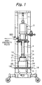
- Fig. 1 is an elevational view of a pressure pump for high viscosity fluid and Fig. 2 is a side elevational view of the pressure pump shown in Fig. 1, wherein reference numeral 1 designates a base section provided with casters and reference numeral 2 designates a column.
- a can such as drum can, pail can or the like is mounted on the base 1.
- the column 2 is fixed to the base 1 at a bottom thereof and a lift 3 is attached to the column 2.
- the lift 3 is controlled by a controller though not shown.
- the lift 3 has a transport pipe 4 for transporting the high viscosity fluid, and the transport pipe 4 is moved up-and-down along a vertical direction by the lift 3.
- a follow plate unit 5 is attached to a lower end of the transport pipe 4.
- the follow plate unit 5 has a cylindrical follow plate body 6.
- the follow plate body 6 has a vertical center through hole, which is a guide passage 7 for the high viscosity fluid.
- a lower portion of the follow plate body 6 is formed into two steps of annular steps 9 and 10.
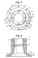
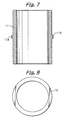
- the follow plate body 6 is inserted into a cylinder liner 11 which is shown in an enlarged drawing of Fig. 7.
- a ring plate 12 shown in an enlarged drawing of Fig. 8 is placed on the annular step 7 of the follow plate body 6.
- the annular step 9 of the follow plate body 6 serves as a bearing surface on which a lower end of the liner cylinder 11 abuts.
- a fixing flange 13 is attached to a lower end of the transport pipe 4, and the follow plate body 6 is fixed to the fixing flange 13 by a connecting bolt 14.
- the liner cylinder 11 is vertically clamped by and fixed between the ring plate 12 and the annular step 9.
- the liner cylinder 11 has an annular flange 11A formed on an outer surface thereof in a middle portion with respect to a vertical direction.
- the annular flange 11A has an annular groove 11B formed thereon for receiving O-ring.
- the annular flange 11A cooperates with a cylinder described later to form a pressure chamber on each of an upper and a lower sides of the annular flange 11A respectively.
- a plurality of threaded holes 14 is formed on the annular step 10 of the follow plate body 6 along a pitch circle placing a specified distance between holes.
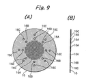
- the lower plate 16 has a plurality of small holes 16A in a central portion thereof for filtering the high viscosity fluid and also a plurality of through holes 16B, 16C for screw each disposed outer side of the small holes along respective pitch circles placing respective specified distances between holes respectively, wherein an arrangement of the holes 16B corresponds to that of the threaded holes 14 so that the connecting screw 15 may be applied through them.
- a ring type upper plate 17 shown in enlarged drawings of Figs. 10(A), 10(B) is disposed on an upper surface of the annular step 10.
- the upper plate 17A is provided with a plurality of holes 17A, 17B for screw each disposed along respective pitch circles placing respective specified distances between holes respectively.
- An ring type elastic sealing member 18 is disposed between the upper plate 17 and the lower plate 16. As shown in enlarged drawings of Figs. 11(A), 11(B), the ring type elastic sealing member 18 is composed of an upper ring type elastic sealing member 18A and a lower ring type elastic sealing member 18B.
- the upper ring type elastic sealing member 18A and the lower ring type elastic sealing member 18B are bonded with each other at outer peripheries thereof to form the outer peripheries into a contact portion 18C for being brought into contact with a wall inner surface of the can.
- Each of the elastic sealing members 18A, 18B is provided with a plurality of through holes 18D, 18D' for screw formed near to an inner boundary thereof along a pitch circle placing a specified distance between holes.
- the through holes 18D for screw are disposed so as for a position thereof to correspond to that of the through holes 17B for screw of the upper plate 17.
- the through holes for screw 18D' are disposed so as for a position thereof to correspond to that of the through holes 16C for screw of the lower plate 16.
- Two sheets of support plates 19, 20 are inserted between the upper ring type elastic sealing member 18A and the lower ring type elastic sealing member 18B.
- each of the support plates 19, 20 is composed of a pair of semicircular ring plates 21.
- a plurality of threaded holes 21A is formed on the semicircular ring plate 21 along a pitch circle placing a specified distance between holes.
- the lower ring type elastic sealing member 18B is fixed to the lower plate 16 by a connecting screw 22.
- the upper ring type elastic sealing member 18A is fixed to the upper plate 17 by a connecting screw 23.
- the cylinder 24 is fitted on an upper portion of the liner cylinder 11 from an upper side thereof.
- a lower pressure chamber 27' is defined by the annular flange 11A of the liner cylinder 11, a lower portion of the cylinder 24 and the bottom cylinder sealing ring 25, while an upper pressure chamber 28' is defined by the annular flange 11A of the liner cylinder 11, an upper portion of the cylinder 24 and a top cylinder sealing ring 26 formed integrally with the cylinder 24.
- the bottom cylinder sealing ring 25 has, as shown in an enlarged drawing of Fig. 13(A), annular grooves 25A, 25B for O-ring, each being formed on an inner surface and on a top surface thereof respectively, and a lower side of the lower pressure chamber 27' is sealed by O-rings fitted in respective annular grooves 25A, 25B.
- An inlet/outlet port 28 for compressed air is formed on a side wall of the bottom cylinder sealing ring 25 so as to communicate with the lower pressure chamber 27'.
- a compressed air supply tube 29A is connected to the inlet/outlet port 28 as shown in Fig. 2, and the compressed air supply tube 29A is also connected through a four way valve 30 and a connector 31 to a compressor though not shown.
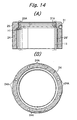
- a plurality of threaded holes 24A is formed on an under surface of the cylinder 24 along a pitch circle placing a specified distance between holes as shown in an enlarged drawing of Fig. 14(B) in a pattern that the position thereof corresponds to that of the through holes 17A of the upper plate 17, and also a plurality of through holes 25C for screw is formed on the bottom cylinder sealing ring 25 along a pitch circle placing a specified distance between holes as shown in Fig. 13(B) in a pattern that the position thereof corresponds to that of the threaded holes 24A so that the bottom cylinder sealing ring 25 is vertically clamped by and fixed between the cylinder 24 and the upper plate 17.
- an annular groove 26A for O-ring is formed on an inner surface of the top cylinder sealing ring 26 and an upper side of the upper pressure chamber 28' is sealed by an O-ring fitted in the annular groove 26A.
- An inlet/outlet port 31 for compressed air is formed on the top cylinder sealing ring 26 so as to communicate with the upper pressure chamber 28', and a compressed air supply tube 29 is connected to the inlet/outlet port 31 for compressed air as shown in Fig. 2, so that the compressed air may flow in or out of the upper pressure chamber 28' through the compressed air supply tube 29.
- a clearance H1 is provided between an opening 28A, 31A of the inlet/outlet port 28, 31 for compressed air and an outer surface of the liner cylinder 11, so that the compressed air can easily flow into or out of the lower pressure chamber 27' and the upper pressure chamber 28' through the clearance H1.
- the transport pipe 4 is moved downward and thereby the follow plate unit 5 is moved downward when the high viscosity fluid stored in the can 32A is to be pumped by pressure.
- the compressed air is supplied to the lower pressure chamber 27' and thereby the upper plate 17 is moved downward to extend the outer diameter of the ring type elastic sealing member 18 and to bring an outer end face of the contact portion 18C into contact with a wall inner surface 32C of the can 32A.
- the follow plate unit 5 When the follow plate unit 5 reaches down to a bottom 32E of the can 32A and almost all of the high viscosity fluid 32B has been discharged, the follow plate unit 5 is moved upward by moving the transport pipe 4 upward. At the same time, the compressed air is supplied to the upper pressure chamber 28' to expand a volume of the upper pressure chamber 28' and to reduce that of the lower pressure chamber 27', and thereby the upper plate 17 is moved upward together with the cylinder 24. Along with the upper plate 17 is moved upward the upper ring type elastic sealing member 18A which is fixed to the upper plate 17.
- the follow plate unit can be smoothly retracted from the can without deteriorating a sealing capacity for drawing the high viscosity fluid out of the can and also an assembling operation thereof can be performed easily.
Landscapes
- Engineering & Computer Science (AREA)
- Mechanical Engineering (AREA)
- General Engineering & Computer Science (AREA)
- Reciprocating Pumps (AREA)
- Details Of Reciprocating Pumps (AREA)
- Details Of Rigid Or Semi-Rigid Containers (AREA)
Applications Claiming Priority (2)
| Application Number | Priority Date | Filing Date | Title |
|---|---|---|---|
| JP2000025532 | 2000-02-02 | ||
| JP2000025532A JP3297661B2 (ja) | 2000-02-02 | 2000-02-02 | 高粘度流体圧送用ポンプ装置 |
Publications (3)
| Publication Number | Publication Date |
|---|---|
| EP1122434A2 true EP1122434A2 (fr) | 2001-08-08 |
| EP1122434A3 EP1122434A3 (fr) | 2003-03-05 |
| EP1122434B1 EP1122434B1 (fr) | 2006-08-23 |
Family
ID=18551381
Family Applications (1)
| Application Number | Title | Priority Date | Filing Date |
|---|---|---|---|
| EP00123765A Expired - Lifetime EP1122434B1 (fr) | 2000-02-02 | 2000-11-01 | Pompe à pression pour un fluide visqueux |
Country Status (4)
| Country | Link |
|---|---|
| US (1) | US6422430B1 (fr) |
| EP (1) | EP1122434B1 (fr) |
| JP (1) | JP3297661B2 (fr) |
| DE (1) | DE60030247T2 (fr) |
Cited By (2)
| Publication number | Priority date | Publication date | Assignee | Title |
|---|---|---|---|---|
| US6422430B1 (en) * | 2000-02-02 | 2002-07-23 | Yamada Corporation | Pressure pump for high viscosity fluid |
| CN108860914A (zh) * | 2018-05-15 | 2018-11-23 | 杨桂凤 | 一种可智能液压调节的面料盛放货架装置 |
Families Citing this family (6)
| Publication number | Priority date | Publication date | Assignee | Title |
|---|---|---|---|---|
| US6860696B2 (en) * | 2002-04-18 | 2005-03-01 | Alberto Bazan | System and method for unloading a viscous product from a bag |
| DE102005049805B4 (de) * | 2005-08-19 | 2007-06-14 | Erich Scheugenpflug | Entleervorrichtung |
| US8708201B2 (en) * | 2010-01-12 | 2014-04-29 | Graco Minnesota Inc. | Modular platen assembly for inductor pump |
| DE102013005965A1 (de) * | 2013-04-09 | 2014-10-09 | Udo Tartler | Vorrichtung zum Abdichten und Evakuieren eines Behälters mit insbesondere pastöser Flüssigkeit |
| CN104612930A (zh) * | 2015-01-28 | 2015-05-13 | 宜兴市宙斯泵业有限公司 | 一种输浆泵 |
| US10486958B1 (en) * | 2018-08-27 | 2019-11-26 | Integrated Dispense Solutions | Follower plate geometry |
Citations (3)
| Publication number | Priority date | Publication date | Assignee | Title |
|---|---|---|---|---|
| JPH0882282A (ja) | 1994-09-13 | 1996-03-26 | Nippon Pawaade Kogyo Kk | ポンプ用フォロープレート装置 |
| JP2545679B2 (ja) | 1992-12-04 | 1996-10-23 | 株式会社シー・エス・シー | 高粘度インク用ポンプ |
| JPH118469A (ja) | 1997-06-16 | 1999-01-12 | Hideo Honma | ビアフィリング方法 |
Family Cites Families (8)
| Publication number | Priority date | Publication date | Assignee | Title |
|---|---|---|---|---|
| US2630248A (en) * | 1948-10-08 | 1953-03-03 | Dirkes Ind Inc | Pump for dispensing fluid substances from containers |
| DE3215817A1 (de) * | 1981-04-30 | 1982-11-18 | Toyo Special Machinery Co. Ltd., Tokyo | Pumpvorrichtung |
| DE3128156C2 (de) | 1981-07-16 | 1985-01-24 | J.M. Voith Gmbh, 7920 Heidenheim | Siebpartie einer Papiermaschine |
| US4661688A (en) * | 1985-11-27 | 1987-04-28 | Nordson Corporation | Bulk melter platen assembly |
| US4792063A (en) * | 1987-12-18 | 1988-12-20 | Industrial Machine Manufacturing, Inc. | Follower plate assembly |
| US5137368A (en) * | 1989-06-21 | 1992-08-11 | Specified Equipment Systems Co., Inc. | Viscous fluid pumping apparatus and system |
| US5746112A (en) * | 1996-11-20 | 1998-05-05 | Watson; M. Burnell | Piston for tank |
| JP3297661B2 (ja) * | 2000-02-02 | 2002-07-02 | 株式会社ヤマダコーポレーション | 高粘度流体圧送用ポンプ装置 |
-
2000
- 2000-02-02 JP JP2000025532A patent/JP3297661B2/ja not_active Expired - Lifetime
- 2000-10-27 US US09/697,504 patent/US6422430B1/en not_active Expired - Lifetime
- 2000-11-01 EP EP00123765A patent/EP1122434B1/fr not_active Expired - Lifetime
- 2000-11-01 DE DE60030247T patent/DE60030247T2/de not_active Expired - Lifetime
Patent Citations (3)
| Publication number | Priority date | Publication date | Assignee | Title |
|---|---|---|---|---|
| JP2545679B2 (ja) | 1992-12-04 | 1996-10-23 | 株式会社シー・エス・シー | 高粘度インク用ポンプ |
| JPH0882282A (ja) | 1994-09-13 | 1996-03-26 | Nippon Pawaade Kogyo Kk | ポンプ用フォロープレート装置 |
| JPH118469A (ja) | 1997-06-16 | 1999-01-12 | Hideo Honma | ビアフィリング方法 |
Cited By (2)
| Publication number | Priority date | Publication date | Assignee | Title |
|---|---|---|---|---|
| US6422430B1 (en) * | 2000-02-02 | 2002-07-23 | Yamada Corporation | Pressure pump for high viscosity fluid |
| CN108860914A (zh) * | 2018-05-15 | 2018-11-23 | 杨桂凤 | 一种可智能液压调节的面料盛放货架装置 |
Also Published As
| Publication number | Publication date |
|---|---|
| JP2001214854A (ja) | 2001-08-10 |
| EP1122434B1 (fr) | 2006-08-23 |
| EP1122434A3 (fr) | 2003-03-05 |
| DE60030247T2 (de) | 2007-09-20 |
| US6422430B1 (en) | 2002-07-23 |
| JP3297661B2 (ja) | 2002-07-02 |
| DE60030247D1 (de) | 2006-10-05 |
Similar Documents
| Publication | Publication Date | Title |
|---|---|---|
| US5141412A (en) | Double acting bellows-type pump | |
| EP1674143B1 (fr) | Filtres | |
| US4536134A (en) | Piston seal access apparatus | |
| US5634779A (en) | Hydraulic fluid-driven, multicylinder, modular reciprocating piston pump | |
| EP3111089B1 (fr) | Pompe à soufflet à entraînement hydraulique | |
| US6016738A (en) | Piston compressor of the horizontal type | |
| EP1122434B1 (fr) | Pompe à pression pour un fluide visqueux | |
| KR20120099062A (ko) | 피스톤 펌프 | |
| KR20080100364A (ko) | 어큐뮬레이터 | |
| GB2161221A (en) | Flexible chamber pump | |
| JP2006207410A (ja) | ベローズポンプ | |
| JPH0777163A (ja) | ダイヤフラムポンプ | |
| EP0666420B1 (fr) | Dispositif d'actionnement de piston à pression de fluide | |
| US5624246A (en) | Hydraulic ammonia solution pump | |
| US3939872A (en) | Pressure transfer unit | |
| US20230332590A1 (en) | Air operated double diaphragm pump with accessible features | |
| KR101335097B1 (ko) | 에어 브리더 | |
| US20130015117A1 (en) | Drainage device for closed chamber containing liquid | |
| JP3576245B2 (ja) | プランジャーポンプ | |
| CN222863723U (zh) | 仓储设备用集成液压泵组 | |
| JPH0762473B2 (ja) | ポンプ装置 | |
| US4720247A (en) | Oil well pump | |
| JPS5823985Y2 (ja) | 高粘度液用ポンプ | |
| JP7169893B2 (ja) | ローリングダイアフラムポンプ | |
| JPS5830150Y2 (ja) | ダイアフラムポンプ |
Legal Events
| Date | Code | Title | Description |
|---|---|---|---|
| PUAI | Public reference made under article 153(3) epc to a published international application that has entered the european phase |
Free format text: ORIGINAL CODE: 0009012 |
|
| AK | Designated contracting states |
Kind code of ref document: A2 Designated state(s): AT BE CH CY DE DK ES FI FR GB GR IE IT LI LU MC NL PT SE TR |
|
| AX | Request for extension of the european patent |
Free format text: AL;LT;LV;MK;RO;SI |
|
| PUAL | Search report despatched |
Free format text: ORIGINAL CODE: 0009013 |
|
| AK | Designated contracting states |
Kind code of ref document: A3 Designated state(s): AT BE CH CY DE DK ES FI FR GB GR IE IT LI LU MC NL PT SE TR |
|
| AX | Request for extension of the european patent |
Extension state: AL LT LV MK RO SI |
|
| RIC1 | Information provided on ipc code assigned before grant |
Ipc: 7F 04B 43/10 A |
|
| 17P | Request for examination filed |
Effective date: 20030505 |
|
| AKX | Designation fees paid |
Designated state(s): DE FR GB IT NL SE |
|
| 17Q | First examination report despatched |
Effective date: 20040503 |
|
| GRAP | Despatch of communication of intention to grant a patent |
Free format text: ORIGINAL CODE: EPIDOSNIGR1 |
|
| RIN1 | Information on inventor provided before grant (corrected) |
Inventor name: ITO, KIKUO,C/O YAMADA CORPORATION |
|
| GRAS | Grant fee paid |
Free format text: ORIGINAL CODE: EPIDOSNIGR3 |
|
| GRAA | (expected) grant |
Free format text: ORIGINAL CODE: 0009210 |
|
| AK | Designated contracting states |
Kind code of ref document: B1 Designated state(s): DE FR GB IT NL SE |
|
| PG25 | Lapsed in a contracting state [announced via postgrant information from national office to epo] |
Ref country code: IT Free format text: LAPSE BECAUSE OF FAILURE TO SUBMIT A TRANSLATION OF THE DESCRIPTION OR TO PAY THE FEE WITHIN THE PRESCRIBED TIME-LIMIT;WARNING: LAPSES OF ITALIAN PATENTS WITH EFFECTIVE DATE BEFORE 2007 MAY HAVE OCCURRED AT ANY TIME BEFORE 2007. THE CORRECT EFFECTIVE DATE MAY BE DIFFERENT FROM THE ONE RECORDED. Effective date: 20060823 |
|
| REG | Reference to a national code |
Ref country code: GB Ref legal event code: FG4D |
|
| REF | Corresponds to: |
Ref document number: 60030247 Country of ref document: DE Date of ref document: 20061005 Kind code of ref document: P |
|
| REG | Reference to a national code |
Ref country code: SE Ref legal event code: TRGR |
|
| ET | Fr: translation filed | ||
| PLBE | No opposition filed within time limit |
Free format text: ORIGINAL CODE: 0009261 |
|
| STAA | Information on the status of an ep patent application or granted ep patent |
Free format text: STATUS: NO OPPOSITION FILED WITHIN TIME LIMIT |
|
| 26N | No opposition filed |
Effective date: 20070524 |
|
| PGFP | Annual fee paid to national office [announced via postgrant information from national office to epo] |
Ref country code: SE Payment date: 20091126 Year of fee payment: 10 Ref country code: DE Payment date: 20091130 Year of fee payment: 10 |
|
| PGFP | Annual fee paid to national office [announced via postgrant information from national office to epo] |
Ref country code: NL Payment date: 20091130 Year of fee payment: 10 |
|
| PGFP | Annual fee paid to national office [announced via postgrant information from national office to epo] |
Ref country code: FR Payment date: 20091027 Year of fee payment: 10 Ref country code: GB Payment date: 20091127 Year of fee payment: 10 |
|
| PG25 | Lapsed in a contracting state [announced via postgrant information from national office to epo] |
Ref country code: IT Free format text: LAPSE BECAUSE OF NON-PAYMENT OF DUE FEES Effective date: 20091101 |
|
| REG | Reference to a national code |
Ref country code: NL Ref legal event code: V1 Effective date: 20110601 |
|
| REG | Reference to a national code |
Ref country code: SE Ref legal event code: EUG |
|
| GBPC | Gb: european patent ceased through non-payment of renewal fee |
Effective date: 20101101 |
|
| PGFP | Annual fee paid to national office [announced via postgrant information from national office to epo] |
Ref country code: IT Payment date: 20091113 Year of fee payment: 10 |
|
| PGRI | Patent reinstated in contracting state [announced from national office to epo] |
Ref country code: IT Effective date: 20110616 |
|
| REG | Reference to a national code |
Ref country code: FR Ref legal event code: ST Effective date: 20110801 |
|
| PG25 | Lapsed in a contracting state [announced via postgrant information from national office to epo] |
Ref country code: NL Free format text: LAPSE BECAUSE OF NON-PAYMENT OF DUE FEES Effective date: 20110601 |
|
| REG | Reference to a national code |
Ref country code: DE Ref legal event code: R119 Ref document number: 60030247 Country of ref document: DE Effective date: 20110601 Ref country code: DE Ref legal event code: R119 Ref document number: 60030247 Country of ref document: DE Effective date: 20110531 |
|
| PG25 | Lapsed in a contracting state [announced via postgrant information from national office to epo] |
Ref country code: SE Free format text: LAPSE BECAUSE OF NON-PAYMENT OF DUE FEES Effective date: 20101102 Ref country code: DE Free format text: LAPSE BECAUSE OF NON-PAYMENT OF DUE FEES Effective date: 20110531 |
|
| PG25 | Lapsed in a contracting state [announced via postgrant information from national office to epo] |
Ref country code: FR Free format text: LAPSE BECAUSE OF NON-PAYMENT OF DUE FEES Effective date: 20101130 |
|
| PG25 | Lapsed in a contracting state [announced via postgrant information from national office to epo] |
Ref country code: GB Free format text: LAPSE BECAUSE OF NON-PAYMENT OF DUE FEES Effective date: 20101101 |
|
| PGRI | Patent reinstated in contracting state [announced from national office to epo] |
Ref country code: IT Effective date: 20110616 |