EP1122692A2 - Système informatisé de dessin - Google Patents
Système informatisé de dessin Download PDFInfo
- Publication number
- EP1122692A2 EP1122692A2 EP01102391A EP01102391A EP1122692A2 EP 1122692 A2 EP1122692 A2 EP 1122692A2 EP 01102391 A EP01102391 A EP 01102391A EP 01102391 A EP01102391 A EP 01102391A EP 1122692 A2 EP1122692 A2 EP 1122692A2
- Authority
- EP
- European Patent Office
- Prior art keywords
- model
- data
- updated
- components
- model component
- Prior art date
- Legal status (The legal status is an assumption and is not a legal conclusion. Google has not performed a legal analysis and makes no representation as to the accuracy of the status listed.)
- Ceased
Links
Images



Classifications
-
- G—PHYSICS
- G06—COMPUTING OR CALCULATING; COUNTING
- G06T—IMAGE DATA PROCESSING OR GENERATION, IN GENERAL
- G06T19/00—Manipulating three-dimensional [3D] models or images for computer graphics
-
- G—PHYSICS
- G06—COMPUTING OR CALCULATING; COUNTING
- G06T—IMAGE DATA PROCESSING OR GENERATION, IN GENERAL
- G06T2219/00—Indexing scheme for manipulating 3D models or images for computer graphics
- G06T2219/004—Annotating, labelling
Definitions
- Computer-aided design (CAD) software allows a user to construct and manipulate design models representing complex three-dimensional (3D) objects.
- a number of different modeling techniques can be used to model a 3D object. These techniques include constructive solid geometry (CSG) modeling, boundary representation (BREP) modeling, and hybrid systems combining CSG and BREP modeling techniques. Other techniques are also known.
- CAD systems can combine basic modeling techniques with parametric modeling technologies that allow a model designer to define parameters interconnecting different components of a model. Parametric modeling can facilitate propagating changes among components.
- a designer can model a 3D object from a collection of assemblies, subassemblies, and parts (collectively referred to as model "components").
- a designer constructs these components (or obtains them from a library of pre-constructed components) and then brings the components together to form other components (i.e., assemblies) and, ultimately, to form the model.
- Each component may be stored as a separate computer document (i.e., a separate file in a local or distributed file system).
- Each component document can, in turn, reference other component documents.
- the design of the different components of the clock e.g., of the gears, the hands, and the housing
- the clock model which is an assembly of these components, is formed using another data document that specifies relationships among these individual component documents (and possibly among other component documents).
- a movement mechanism document can assemble the components of a clock movement mechanism by bringing together (using mating relationships) a collection of gear parts.
- the movement mechanism document (as well as, e.g., the design documents for the second and minute hands parts) may then be referenced by a clock assembly document.
- the clock assembly document may include mating relationships that interconnect the minute hand and second hand parts to the movement mechanism.
- part and assembly documents can be referenced multiple times by other assembly documents. For example, the same gear design may be used four times in the clock's movement mechanism; this would result in the gear part document being referenced four times in the movement mechanism document.
- Drawings are 2D projected views of the 3D model. Drawings may be created for a variety of purposes, such as to show a machine operator or a product assembler how to make a part and how to assemble parts into a final product. Each drawing may be stored as a separate drawing document on the CAD system. Drawing documents are self-contained insofar as the 2D projected view represented by the drawing document's data can be rendered (displayed) without having to access the various model documents used in the formation of the drawing document.
- the CAD software constructs the model of the object from the various component documents referenced by the model's document. This construction process includes accessing data in all document files that are referenced (directly or indirectly) by the model document.
- the CAD software accesses the clock model document; (ii) accesses documents for components referenced in the clock model document (i.e., the movement mechanism, minute hand, second hand, and clock housing documents); (iii) accesses documents for components referenced in the movement mechanism document; (iv) constructs the 3D model from each of the accessed documents, (iv) generate a 2D projected view from the 3D model; (v) stores the 2D projected view in a drawing document.
- a 2D projected view can be stored in the drawing document using a vector graphic format.
- Vector graphics are used to represent image as a collection of lines, splines, polygons, bounded regions, and other two-dimensional shapes.
- Example vector graphic formats include the scalable vector graphics (SVG) file format, the Adobe Illustrator (AI) file format, the Adobe Portable Document Format (PDF), and others.
- the invention features a computer-implemented method for processing a design model generated by a computer aided design system.
- the method includes accessing model data (which includes a collection of separately stored data documents that detail construction of the design model from a collection of components), processing the model data to generate image elements representing a projected view of the design model and to generate tag data associating each of the image elements with at least one of the model components, and storing the image elements and the tag data in a drawing document.
- the invention features a computer-implemented method for processing a drawing document generated by a computer aided design system.
- the drawing document includes image elements (e.g., vector drawing data) that can be rendered to display a 2D projected view of a 3D model and tag data associating each image element with components of the design model (with at least two of the components referenced by the tag data being specified in separately stored data documents).
- the method includes processing the drawing document to display the view of a design model on a computer display terminal, receiving a user input selecting one of the image elements, receiving supplementary data, and linking the supplementary data to one of the model components based on the tag data associating the selected image element with the first model component.
- the model components may be interrelated by a hierarchical data structure in which the hierarchical relationships detail a construction of the modeled object.
- the hierarchical data structure may be a tree structure that includes parent-child relationships between the model components.
- Each of the model components may detail numerous structural features.
- a model component may detail structural features such as the edges, vertices, and surfaces (as well as three dimensional interconnections between these structural features) for a modeled part or assembly.
- the tag data can associate each image element with a structural feature of a model component.
- the image elements can include vector image drawing data (e.g., lines, polygons, poly-lines, and filled regions) enable a two-dimensional rendering of a 3D model.
- Each of the model's structural features (which includes each of the structural features from each of the model components) may be uniquely labeled by parametric data.
- the tag data may be derived from this parametric data (e.g., by copying the parametric data for use as the tag data, by creating pointers to the parametric data, by generating unique numeric references identifying the parametric data or indexing a table or database containing the parametric data, or by deriving URL or other file system paths that may incorporate all or parts of the parametric data to identifying a referenced structural feature).
- supplementary data can be added to a drawing data file and associated with a particular structural feature of a model without requiring access to the model document or model component documents.
- Adding additional data to a drawing can include selecting one of the image data elements in the drawing, processing tag data to identify a structural feature associated with the first image data element (in some implementations, this processing may be accomplished by searching a table stored in the drawing document that matches image elements with parametric data), receiving the supplementary data, the supplementary data to the drawing data, and storing the supplemented drawing data.
- the supplemented drawing data may include the original (pre-annotated) drawing data, the supplementary data, and pointer data associating the supplementary data with components of the 3D design model (and/or with structural features of those components).
- the supplementary data may be preserved when the drawing is updated (e.g., in response to changes in the underlying model or to a model component).
- This "preservation" of the data refers, generally, to an ability to preserve relationships between supplementary data and drawing document image elements when the drawing document is updated (e.g., in response to a change in the underlying 3D model data).
- Preservation of the supplementary data can include processing updated model data to generate new drawing, extracting supplementary data from an existing drawing, and transferring the extracted supplementary data to the new drawing document.
- the process of transferring the supplementary data uses the tag data associated with the image elements in the original drawing and the tag data associated with the image elements in the updated drawing to maintain matchings between the supplementary data and the proper image elements.
- the supplementary data can be an annotation identifying a desired change in a model component.
- a user may add an annotation (e.g., a size value) indicating that a particular component should be reduced in size.
- Implementations can process this annotations by "pushing" the size value data from drawing data file to the model component itself to alter the model data in accordance with the identified change.
- Implementations may include one or more of the following advantages.
- a user can send a drawing file to another CAD user without sending associated model files (i.e., model component files), while still permitting the other CAD user to annotate and change the model file.
- Annotations to a drawing file can be automatically maintained and updated as underlying model data is changed.
- Annotations in a drawing document can be fully associative (i.e. the annotations remain attached to particular structural features of the model when the drawing document changes in response to model changes).
- Drawing documents can be opened, and annotations can be attached to structural features of a 3D model without requiring access to other model documents. Users can control when a drawing is updated to the model (i.e. the synchronization process of the drawing documents is responsive may be controlled by the user). In other implementations, the synchronization process may be automatic.
- Two-dimensional (2D) drawing documents that are created from 3D models may be enhanced through the addition of annotations added by a user using a computer-based annotation tool.
- annotations include, e.g., symbols indicating surface finishes and weld points, text notes, dimension measurements, and other types of supplementary data (i.e., data supplementing that found in the model and/or model component documents).
- Annotations may be attached to particular edges, vertices, faces, or other model elements visible in a drawing.
- annotations are added by selecting an arc, line, polygon, or other element of the 2-D drawing, and then attaching the annotation to the selected element.
- the annotation software (i) identifies the selected element of the 2-D drawing, and then (ii) analyzes the model to determine the part corresponding to the selected element. Determining the part corresponding to the selected feature may require that the annotation software access each document file that referenced (directly or indirectly) in constructing the modeled object. For complex documents, opening each document file referenced in constructing the modeled object can require a significant amount of processing resources. Consequently, improved systems for annotating and otherwise manipulating 2-D drawings are desired.
- Improved annotation, editing, addition of supplementary data, and other manipulations of 2-D drawings created by a CAD system can be accomplished using a drawing document format that includes image elements (e.g., vector drawing data) along with tag data that associates the image elements with the model components represented by the image elements.
- image elements e.g., vector drawing data
- tag data that associates the image elements with the model components represented by the image elements.
- This association between tag data and image elements provides a linkage to components of a design model that are specified in other data documents (i.e., data files) and which are processed to generate the drawing document.
- Software tools can use the tag data in the drawing document to link supplementary data to model components without having to have actual access to the data documents in which the model components are specified.
- the drawing document can be updated in response to a change in the data in the model component documents, and the linkages between supplementary data and particular model components can be retained, using this tag data.
- Fig. 1 shows a computerized modeling system 130 that includes a CPU 131, a CRT 132, a keyboard input device 133, a mouse input device 134, and a storage device 135.
- the CPU 131, CRT 132, keyboard 133, mouse 134, and storage device 135 can include commonly available computer hardware devices such as a Pentium-based computer.
- the mouse 134 has conventional left and right buttons that the user may press to issue a command to a computer-aided design (CAD) software program being executed by the CPU 131.
- CAD computer-aided design
- Other appropriate computer hardware platforms are suitable as will become apparent from the discussion that follows. Typically, such computer hardware platforms include an operating system such as Microsoft Windows 2000TM, UNIXTM, LINUXTM, or other operating system.
- CAD software is stored on the storage device 135 and is loaded into and executed by the CPU 131.
- this software allows the user to create and modify a 3D model, to produce 2D drawings, and to implement other aspects of the invention described herein.
- the CPU 131 uses the CRT 132 to display projected views of the 3D model as described in more detail below. Projected views of the 3D model can also be stored in drawing documents and can be output to other devices (e.g., printers, plotters, and to manufacturing and machine control systems).
- a user actuates the keyboard 133 and the mouse 134 to enter and modify data for the 3D model.
- the CPU 131 accepts and processes input from the keyboard 133 and mouse 134.
- the CPU 131 processes the input along with the data associated with the 3D model and makes corresponding changes to the display on the CRT 132.
- Other input devices e.g., voice dictation software and graphic tablets
- other output devices e.g., a laser printer or plotter
- Fig. 2A shows an example of a CRT 132 display during the model-design process.
- the display 200 shows a graphical user interface (GUI) display window produced in a Microsoft Windows NTTM-based implementation.
- the window 240 includes a modeling portion 242 that displays projected views 210 of a 3D model.
- the particular view shown in Fig. 2A is an isometric view of a 3D model that assembles together three parts: a bolt, a lock washer, and a flat washer to form a bolt assembly 210.
- the design tree 260 shows a hierarchy of different model components and modeling operations that are brought together in the modeling of the bolt assembly shown in window 242.
- the label 269 identifies the highest level of the design hierarchy for the bolt assembly 210.
- the design tree 260 also identifies a hierarchy of the other document files parts (and the associated components) referenced by the bolt assembly document 269.
- the tree indicates that the bolt assembly document 269 references three parts documents: a bolt document 261, a lock washer document 262, and a flat washer document 263. Additional views of the bolt 211, lock washer 212, and flat washer 213, as individually defined components in documents 261-263, are shown in Fig. 2B.
- the tree 260 indicates that the document 269 includes mating relationships (labeled "MateGroupl") 266 that interconnect components of the modeled bolt assembly 210.
- a designer creates the bolt assembly 210 by bringing together parts 211-213 using mating relationships 266 specified in the bolt assembly document 269.
- the CAD system 100 stores these mating relationships in the bolt assembly document along with references to the individual part documents 261-263 (and, in some cases, to other assembly (i.e., "sub-assembly") documents).
- a particular part or sub-assembly may be referenced multiple times.
- bolt assembly document 269 may be referenced as a sub-assembly of a car door assembly document.
- the car door assembly document may reference the bolt assembly document multiple times (once for each bolt assembly used in the model of the car door).
- Each component and each structural feature (i.e., each edges, vertices, surface, intersection of surfaces, intersection of components) in a model can be tagged with parametric data that uniquely identifies the component and/or structural feature.
- the surface 221 of the bolt may be labeled with the parametric identifier "AAA.221”
- surface 222 may be labeled with the parametric identifier "AAA.222”.
- Additional parametric data may be added within a referencing document or if multiple instances of a component are referenced.
- the surface 221 and 222 may be labeled as "BBB.AAA.221" and "BBB.AAA.222".
- the additional parametric data "BBB” is added in document 269 to identify the referencing document.
- additional data e.g., sequential numbers “1", “2", “3”
- the surface 221 may be identified as "BBB.2.AAA.222”.
- a structural feature e.g., an intersection
- each line, arc, polygon, rectangle, circle, ellipse, line, polyline, polygon, boundary, or other image data element in the drawing file may be tagged with parametric data identifying a corresponding edge, vertices, face, or surface of a model component.
- the hierarchical structure of assemblies, sub-assemblies, parts, and their mating relationships controls the rendering of a modeled object by the CAD software and the creation of drawing (i.e., 2D projections of the modeled object).
- the CAD software accesses the data in each of component document that is referenced (directly or indirectly) in another document. For example, in the case of the bolt assembly 210, the CAD software accesses a document for the assembly 210 as well as the bolt part document, a lock washer document, and a flat washer document (a total of four documents).
- the CAD software then constructs a 3D model of the assembly 210 using data obtained from the four documents.
- the CAD software can then render a projected view of the modeled object by determining a collection of arcs, polygons, rectangles, circles, ellipses, lines, polylines, polygons, bounded regions, and other image elements.
- the image elements forming the projected view can be stored in a stand-alone 2D drawing document. By stand-alone, what is meant is that access to the 3D model document files is not needed for the display of the 2D drawing.
- Each vector image element in the 2D drawing document is derived from a component of the 3D model.
- a vector image element i.e., the vertical line "Edge B”
- each vector image element can be tagged with the parametric data that identifies the model component that the image element represents.
- the line representing edge B may be tagged with the parametric data "AAA.221:AAA.222" to indicate that the image element represents an edge between surfaces 221 and 222.
- the system 100 can generate a 2D drawing document in which each image element is tagged with parametric data identifying the 3D model component(s) represented (in whole or in part) by the tagged image element.
- the drawing document stores image elements and tags such that the structural features of the particular model component(s) represented by an image element can be determined.
- the way in which the 2D vector image element is tagged with the parametric data will depend on the particular image element format.
- the parametric data may be associated with an image data element using the SVG 'a' element to insert parametric data in the form of a hyperlink.
- SVG foreign namespace and/or private data can be used to associate the parametric data with an image data element.
- Other implementations can embed the parametric data in the form of comments, pointers, or other data type.
- each element may have a simple identifier referencing a table in which the parametric data (as well as supplementary data, discussed below) can be stored. Still other formats can be used.
- supplementary data may be added to the drawing document by the user.
- Annotations are an example of supplementary data that can be added to the 2D drawing file.
- Annotations can include text-based notes, graphical symbols, dimensions, and other types of data.
- the drawing document is rendered on a computer display terminal and the user selects an image element displayed on the terminal.
- the image element can be selected, e.g., using a pointer displayed on the terminal and manipulated by a mouse input device.
- the ability to select image elements displayed on a terminal is known in the art and is used, for example, in conventional vector image drawing software.
- the user may then activate a procedure allowing supplementary data to be input. Different procedures for adding data can be selected using menu or icon selection or by keyboard input. For example, by selecting appropriate menu items, the user may indicate that a text annotation, a dimension symbol, a welding symbol, or other supplementary data is to be added. In some cases (e.g., when the supplementary data is text), a dialog box may be displayed allowing the user to input the supplementary data.
- Parametric data associated with the selected image element(s) can be used to link the supplementary data with the structural features (i.e., components, component intersections, assemblies of components, and/or particular sub-features of components or component assemblies) of the design model represented by the image element.
- a text-based note can be linked to the vertical line image element representing "Edge B" of Fig. 2A such that the note is displayed at a particular location relative to the image element.
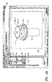
- a dimension symbol 301 can be added to a 2D document to indicate the diameter of the top surface 223 of the bolt.
- a measurement (“15.60") displayed as part of the dimension symbol 301 is automatically determined based on data (e.g., a drawing scale or measurements pre-computed in forming the drawing document) that is stored in the drawing document. Supplementary data may then be stored in the drawing file. This linking of supplementary data to the model components is based on the tag data in the drawing document and does not require access to the model component documents.
- Using tag data to create linkages between the supplementary data and the 3D model components helps to maintain associations between the supplementary data and the 3D model components when components of the model are changed. For example, if the diameter of the top surface 223 of the bolt is reduced (i.e., by changing it in the document file 261), a new drawing 400 (Fig. 4) that shows the effect of reducing the diameter of top surface 223 can be produced.
- the supplementary data e.g., annotation 301
- the diameter annotation 301 can be automatically transferred to retain the dimension annotation as annotation 501 (Fig. 5). Note that, as shown in Fig. 5, the annotation 501 may be automatically updated with the new dimension value ("4.40").
- the automatic transfer of supplementary data is guided by the parametric data included in a drawing document when the drawing document is produced from a 3D model.
- the system 100 looks for matches between parametric data in the original document and in the updated drawing documents to control the linking of supplementary data in the updated drawing document. For example, assume that the supplementary data "DATAVALUE1" is stored in an original drawing document and is associated with an image element that is linked to a model component by the parametric tag "AAA123.”
- the system 100 extracts the data value "DATAVALUE1" from the original drawing document and searches the updated drawing document for an image element bearing the parametric tag "AAA123". If such an image element is found, the supplementary data "DATAVALUE1" is transferred to the updated drawing document and is associated with the found image element (and thus linked to the appropriate model component)
- the process of "transferring" supplementary data from a original to an updated drawing document may, in some implementations, be performed by updating data within the original drawing document to, in effect, create the updated drawing document. That is, to produce the "updated” drawing document, the system 100 may update the image elements in the original drawing document to produce the updated drawing document.
- the "transfer" of supplementary data from the original to the updated drawing document does not require an actual movement of the supplementary data between different drawing documents but rather is a logical transfer.
- the system may not be able to locate an image element in the updated drawing document that is tagged with the same tag data as the supplementary data to be transferred from the original drawing document. In such cases, the user may be prompted to re-link the supplementary data or to have it discarded.
- a rebuild function can notify the user that a drawing and an associated design model are not synchronized.
- An update function can automatically update dimensions and annotation, including insertion of balloons and pending changes and bi-directional associative dimensions and annotations.
- supplementary data may also be transferred among multiple different views of the same design model. For example, if a user has linked an annotation 301 to the top surface 223 of the bolt (as shown in the front view of Fig. 3), the system 100 may include that annotation in additional view of the model (e.g., in a top view).
- the system 100 can render a view (a "ghost view") that includes, e.g., visible features rendered using solid lines and hidden features represented using dotted lines.
- a user may be able to use this "ghost view” to link the supplementary data to hidden features.
- This supplementary data may then be automatically transferred to other drawings where the corresponding features are visible.
- annotations are parametrically associated with structural features, "loss" of the annotations can be prevented even where there may be significant alterations in the placement of structural features.
- topology based features would follow their entities around wherever they end up after a change is made. For example, one edge of a square plate is filleted. If an edge (i.e., a structural feature) of a model component becomes shorter or changes location and orientation, the annotation can remain correctly attached.
- annotations may remain attached to the correct structural feature even though the drawing may be rendered from a different perspective.
- the term "document” refers to computer-generated data stored on a data storage media.
- the invention may be implemented in digital electronic circuitry, or in computer hardware, firmware, software, or in combinations of them.
- Apparatus of the invention may be implemented in a computer program product tangibly embodied in a machine-readable storage device for execution by a programmable processor; and method steps of the invention may be performed by a programmable processor executing a program of instructions to perform functions of the invention by operating on input data and generating output.
- the invention may advantageously be implemented in one or more computer programs that are executable on a programmable system including at least one programmable processor coupled to receive data and instructions from, and to transmit data and instructions to, a data storage system, at least one input device, and at least one output device.
- Each computer program may be implemented in a high-level procedural or object-oriented programming language, or in assembly or machine language if desired; and in any case, the language may be a compiled or interpreted language.
- Suitable processors include, by way of example, both general and special purpose microprocessors. Generally, a processor will receive instructions and data from a read-only memory and/or a random access memory.
- Storage devices suitable for tangibly embodying computer program instructions and data include all forms of non-volatile memory, including by way of example semiconductor memory devices, such as EPROM, EEPROM, and flash memory devices; magnetic disks such as internal hard disks and removable disks; magneto-optical disks; and CD-ROM disks. Any of the foregoing may be supplemented by, or incorporated in, specially-designed ASICs (application-specific integrated circuits).
- semiconductor memory devices such as EPROM, EEPROM, and flash memory devices
- magnetic disks such as internal hard disks and removable disks
- magneto-optical disks magneto-optical disks
- CD-ROM disks CD-ROM disks
Landscapes
- Engineering & Computer Science (AREA)
- Computer Graphics (AREA)
- Computer Hardware Design (AREA)
- General Engineering & Computer Science (AREA)
- Software Systems (AREA)
- Physics & Mathematics (AREA)
- General Physics & Mathematics (AREA)
- Theoretical Computer Science (AREA)
- Processing Or Creating Images (AREA)
- Document Processing Apparatus (AREA)
- Information Retrieval, Db Structures And Fs Structures Therefor (AREA)
Applications Claiming Priority (4)
| Application Number | Priority Date | Filing Date | Title |
|---|---|---|---|
| US18007600P | 2000-02-03 | 2000-02-03 | |
| US180076P | 2000-02-03 | ||
| US09/668,852 US6611725B1 (en) | 2000-02-03 | 2000-09-25 | Computer drawing system |
| US668852 | 2000-09-25 |
Publications (2)
| Publication Number | Publication Date |
|---|---|
| EP1122692A2 true EP1122692A2 (fr) | 2001-08-08 |
| EP1122692A3 EP1122692A3 (fr) | 2004-10-06 |
Family
ID=26875963
Family Applications (1)
| Application Number | Title | Priority Date | Filing Date |
|---|---|---|---|
| EP01102391A Ceased EP1122692A3 (fr) | 2000-02-03 | 2001-02-02 | Système informatisé de dessin |
Country Status (4)
| Country | Link |
|---|---|
| US (1) | US6611725B1 (fr) |
| EP (1) | EP1122692A3 (fr) |
| JP (1) | JP3893248B2 (fr) |
| CA (1) | CA2333811C (fr) |
Cited By (9)
| Publication number | Priority date | Publication date | Assignee | Title |
|---|---|---|---|---|
| FR2807184A1 (fr) * | 2000-03-31 | 2001-10-05 | Honda Motor Co Ltd | Procede et appareil de correction de forme graphique pour systeme de cao |
| GB2385158A (en) * | 2002-02-07 | 2003-08-13 | Guang Yang | A system for inserting hierarchical data into an existing document |
| US6871108B2 (en) | 2002-11-19 | 2005-03-22 | Qssolutions, Inc. | System and method for creating a representation of an assembly |
| GB2415520A (en) * | 2004-06-25 | 2005-12-28 | Myriad Vision Ltd | Hierarchical 3D data system |
| WO2006123040A3 (fr) * | 2005-05-19 | 2007-05-10 | Airbus | Procede et dispositif de generation d’un modele parametrique lie a une geometrie 3 d |
| WO2009091559A1 (fr) * | 2008-01-15 | 2009-07-23 | Google Inc. | Annotations tridimensionnelles pour données de visualisation de rues |
| WO2015183539A1 (fr) * | 2014-05-28 | 2015-12-03 | Siemens Product Lifecycle Management Software Inc. | Création d'une documentation de produit tridimensionnelle (3d) associative à partir d'une annotation de dessin |
| WO2016163568A1 (fr) * | 2015-04-08 | 2016-10-13 | 박승철 | Fichier stl comprenant des informations textuelles, et système de recherche et de gestion de fichier stl les utilisant |
| EP4675411A1 (fr) * | 2024-07-05 | 2026-01-07 | Dassault Systèmes | Annotation d'un objet modélisé 3d représentant une partie mécanique de cao ou un assemblage de parties |
Families Citing this family (109)
| Publication number | Priority date | Publication date | Assignee | Title |
|---|---|---|---|---|
| US8432414B2 (en) * | 1997-09-05 | 2013-04-30 | Ecole Polytechnique Federale De Lausanne | Automated annotation of a view |
| US8527872B1 (en) | 2000-01-18 | 2013-09-03 | Autodesk, Inc. | Multiple output device association |
| JP3800916B2 (ja) * | 2000-03-17 | 2006-07-26 | 株式会社日立製作所 | 解析モデル生成装置、解析モデル生成プログラムを記憶した記憶媒体及び記憶装置 |
| US6647305B1 (en) * | 2000-06-19 | 2003-11-11 | David H. Bigelow | Product design system and method |
| US7400334B1 (en) | 2000-09-29 | 2008-07-15 | 809, L.L.C. | Use of vector graphics in paper printing and website development |
| US6978230B1 (en) * | 2000-10-10 | 2005-12-20 | International Business Machines Corporation | Apparatus, system, and method for draping annotations on to a geometric surface |
| US6904392B1 (en) * | 2000-10-13 | 2005-06-07 | Dassault Systemes | Annotation management |
| US7210095B1 (en) * | 2000-10-31 | 2007-04-24 | Cisco Technology, Inc. | Techniques for binding scalable vector graphics to associated information |
| US6906712B2 (en) * | 2000-11-30 | 2005-06-14 | Solidworks Corporation | Automated three-dimensional alternative position viewer |
| US20020075290A1 (en) * | 2000-12-20 | 2002-06-20 | Microsoft Corporation | Incremental and interruptible layout of visual modeling elements |
| US7320120B2 (en) * | 2000-12-20 | 2008-01-15 | Microsoft Corporation | Pluggable notations and semantics for visual modeling elements |
| US6795089B2 (en) | 2000-12-20 | 2004-09-21 | Microsoft Corporation | Dynamic, live surface and model elements for visualization and modeling |
| US7103527B2 (en) * | 2000-12-20 | 2006-09-05 | Microsoft Corporation | Negotiated interconnection of visual modeling elements |
| US7490301B2 (en) * | 2000-12-25 | 2009-02-10 | Fujitsu Limited | Computer readable recording medium storing program for managing CAD data |
| FR2827686B1 (fr) * | 2001-07-19 | 2004-05-28 | Schneider Automation | Utilisation d'hyperliens dans un programme d'une application d'automatisme et station de programmation d'une telle application |
| WO2003017567A1 (fr) * | 2001-08-15 | 2003-02-27 | Bentley Systems, Incorporated | Procede et systeme permettant de stocker des fichiers de donnees de grande taille |
| US7162479B2 (en) * | 2001-08-15 | 2007-01-09 | Bentley Systens, Incorporated | Method and system for storing large data files |
| US20040205518A1 (en) * | 2001-09-21 | 2004-10-14 | Ming-Chih Shih | System and method of measuring a distance between two points of a layout |
| US6907573B2 (en) * | 2001-09-28 | 2005-06-14 | Autodesk, Inc. | Intelligent constraint definitions for assembly part mating |
| AU2002357684A1 (en) * | 2001-10-31 | 2003-05-12 | Essibuy.Com | Interactive electronic references systems and methods |
| US20040080622A1 (en) * | 2001-11-16 | 2004-04-29 | Bernd Gombert | Input device, webcam and screen having a voice input function |
| US7774714B2 (en) * | 2001-12-27 | 2010-08-10 | Siemens Product Lifecycle Management Software Inc. | Computer aided design system having business process attributes |
| US20030126157A1 (en) * | 2001-12-28 | 2003-07-03 | Young Calvin Kayan | Method for automatically organizing template files in a web-based file retrieval sytstem |
| US7079907B2 (en) * | 2002-02-15 | 2006-07-18 | International Business Machines Corporation | Apparatus, system and method for design support for providing information for bi-directional references between design information and geometry information |
| US7085776B2 (en) * | 2002-04-24 | 2006-08-01 | The Boeing Company | Logical hierarchical data model for sharing product information across product families |
| WO2004057439A2 (fr) * | 2002-05-31 | 2004-07-08 | University Of Utah Research Foundation | Systeme et procede d'annotation visuelle et de representation des connaissances |
| US7620904B1 (en) | 2002-06-21 | 2009-11-17 | Autodesk, Inc. | On demand identifier and geometry piece association in computer aided design (CAD) environment |
| US7088360B1 (en) * | 2002-07-20 | 2006-08-08 | Autodesk, Inc. | Simplified identifier generation in a computer aided design (CAD) environment |
| JP4363923B2 (ja) * | 2002-09-26 | 2009-11-11 | 株式会社東芝 | 三次元配置調整cadの物量集計装置、物量集計プログラムおよび物量集計方法 |
| US20040103375A1 (en) * | 2002-11-27 | 2004-05-27 | Rutie Chen | Method and apparatus for automated schematic rendering |
| JP4342193B2 (ja) * | 2003-02-21 | 2009-10-14 | 富士通株式会社 | 三次元cadシステム、部分再投影方法、及びコンピュータプログラム |
| US20040250236A1 (en) * | 2003-04-30 | 2004-12-09 | O'malley Austin | Establishing and maintaining a relationship between a three-dimensional model and related data |
| KR100559730B1 (ko) * | 2003-09-22 | 2006-03-15 | 삼성전자주식회사 | 기록 시스템을 위한 데이터 부호화/복호화 방법 및 장치 |
| US7346838B2 (en) * | 2003-09-25 | 2008-03-18 | Hewlett-Packard Development Company, L.P. | System and method for displaying document metadata |
| US20050071135A1 (en) * | 2003-09-30 | 2005-03-31 | Vredenburgh David W. | Knowledge management system for computer-aided design modeling |
| US20050204303A1 (en) * | 2004-03-15 | 2005-09-15 | Autodesk, Inc. | Transmittal and archive tool in a sheet set manager for a graphics program |
| DE102004022320A1 (de) * | 2004-05-06 | 2005-11-24 | Daimlerchrysler Ag | Elektronische Konstruktionsvorrichtung |
| US8041744B2 (en) * | 2004-06-24 | 2011-10-18 | Tekla Corporation | Computer-aided modeling |
| US7636096B2 (en) * | 2004-06-25 | 2009-12-22 | Autodesk, Inc. | Automatically ballooning an assembly drawing of a computer aided design |
| JP2006079472A (ja) * | 2004-09-10 | 2006-03-23 | Nsk Ltd | 3次元モデル自動構築システム |
| US8245150B2 (en) * | 2004-11-22 | 2012-08-14 | Caterpillar Inc. | Parts catalog system |
| US7583272B2 (en) * | 2004-11-29 | 2009-09-01 | Purdue Research Foundation | Methods for retrieving shapes and drawings |
| EP1672548A1 (fr) * | 2004-12-20 | 2006-06-21 | Dassault Systèmes | Procédé et système pour le rendu d'un objet dans une vue à l'aide d'une base de données de gestion du cycle de vie de produits |
| US20070038947A1 (en) * | 2005-05-19 | 2007-02-15 | Airbus | Method and device for generation of a parametric model associated with a 3D geometry |
| US20070198588A1 (en) * | 2005-10-17 | 2007-08-23 | Siemens Corporate Research Inc | Automatic Qualification of Plant Equipment |
| US8650506B2 (en) * | 2005-11-10 | 2014-02-11 | International Business Machines Corporation | Use of extensible object data to represent a fully qualified solution order |
| EP1804183B1 (fr) * | 2005-12-30 | 2017-06-21 | Dassault Systèmes | Procédé de sélection d'objets dans une base de données PLM et appareil mettant en oeuvre ce procédé |
| EP1804184B1 (fr) * | 2005-12-30 | 2017-06-28 | Dassault Systèmes | Procédé de sélection d'un objet dans une base de données PLM et appareil mettant en oeuvre ce procédé |
| US20070225846A1 (en) * | 2006-03-23 | 2007-09-27 | Bogan William E | Dynamic tracking of compliance with parameter limits in computer-aided design models |
| US7644363B2 (en) * | 2006-04-10 | 2010-01-05 | Autodesk, Inc. | “For-each” label components in CAD drawings |
| US20070285424A1 (en) * | 2006-06-12 | 2007-12-13 | Autodesk, Inc. | Generating annotation graphics in 2D form to model 3D elements |
| US20070288207A1 (en) * | 2006-06-12 | 2007-12-13 | Autodesk, Inc. | Displaying characteristics of a system of interconnected components at different system locations |
| US7724252B2 (en) * | 2006-08-14 | 2010-05-25 | Gaetano Mazzanti | Method for the editing of three-dimensional graphic models |
| US7650565B2 (en) * | 2007-01-31 | 2010-01-19 | Autodesk, Inc. | Method for managing annotations in a computer-aided design drawing |
| CN102289551B (zh) * | 2007-02-07 | 2014-12-03 | 索尤若驱动有限及两合公司 | 用于生成设计变型的设计图的方法 |
| JP5063156B2 (ja) * | 2007-03-22 | 2012-10-31 | 綜研テクニックス株式会社 | 情報管理システムおよび情報管理方法 |
| US20090102832A1 (en) * | 2007-10-17 | 2009-04-23 | Jay Behr | Selective refresh of computer-aided design drawings |
| US20090115782A1 (en) * | 2007-11-05 | 2009-05-07 | Darren Scott Irons | Display of Analytic Objects and Geometric Objects |
| US20090119311A1 (en) * | 2007-11-06 | 2009-05-07 | International Business Machines Corporation | Systems, methods, and computer products for in-place model attribute comparison |
| US20100180236A1 (en) * | 2009-01-09 | 2010-07-15 | Lin Alan C | Setting and previewing method of dynamically orienting 3D models and machines readable medium thereof |
| US8378261B2 (en) * | 2009-09-11 | 2013-02-19 | Honda Motor Co., Ltd. | Automated assembly method for a motor vehicle |
| JP2012043032A (ja) * | 2010-08-13 | 2012-03-01 | Fujitsu Ltd | 設計支援装置、設計支援方法および設計支援プログラム |
| US8443301B1 (en) | 2010-09-27 | 2013-05-14 | Darek Easterly | Inspection reporting including a 3D vehicle model |
| US8847947B2 (en) * | 2010-11-17 | 2014-09-30 | Dassault Systemes | Automatic tolerancing of geometrical templates |
| US20130167016A1 (en) * | 2011-12-21 | 2013-06-27 | The Boeing Company | Panoptic Visualization Document Layout |
| US9483584B2 (en) * | 2012-01-19 | 2016-11-01 | Oracle International Corporation | Collaboration within a visualization application |
| US8823744B2 (en) * | 2012-03-23 | 2014-09-02 | Bluebeam Software, Inc. | Method for indicating annotations associated with a particular display view of a three-dimensional model independent of any display view |
| US20130317786A1 (en) * | 2012-05-24 | 2013-11-28 | Fluor Technologies Corporation | Feature-based rapid structure modeling system |
| US10268662B2 (en) * | 2012-09-10 | 2019-04-23 | The Boeing Company | Panoptic visualization of a document according to the structure thereof |
| WO2014059387A2 (fr) * | 2012-10-11 | 2014-04-17 | Imsi Design, Llc | Procédé destiné à annoter un document affiché sur un dispositif électronique |
| US10929904B1 (en) | 2012-10-23 | 2021-02-23 | Protolabs, Inc. | Automated fabrication price quoting and fabrication ordering for computer-modeled structures |
| US9858245B2 (en) * | 2013-01-28 | 2018-01-02 | The Boeing Company | Panoptic visualization of elements of a complex system using a model viewer |
| CN103106309B (zh) * | 2013-02-06 | 2015-06-17 | 浙江大学 | 计算机辅助设计过程中的草图行为识别方法及系统 |
| CN103136515B (zh) * | 2013-02-06 | 2015-09-23 | 浙江大学 | 基于草图行为序列的创意拐点识别方法及系统 |
| US9606701B1 (en) | 2013-10-14 | 2017-03-28 | Benko, LLC | Automated recommended joining data with presented methods for joining in computer-modeled structures |
| US10373183B1 (en) | 2013-10-16 | 2019-08-06 | Alekhine, Llc | Automatic firm fabrication price quoting and fabrication ordering for computer-modeled joining features and related structures |
| US20150149459A1 (en) * | 2013-11-22 | 2015-05-28 | Mentor Graphics Corporation | Tag Based System For Leveraging Design Data |
| US11537765B1 (en) | 2014-02-20 | 2022-12-27 | Benko, LLC | Placement and pricing of part marks in computer-modeled structures |
| US11410224B1 (en) * | 2014-03-28 | 2022-08-09 | Desprez, Llc | Methods and software for requesting a pricing in an electronic marketplace using a user-modifiable spectrum interface |
| US10552882B1 (en) | 2014-05-20 | 2020-02-04 | Desprez, Llc | Methods and software for enabling custom pricing in an electronic commerce system |
| US10713394B1 (en) | 2014-06-12 | 2020-07-14 | Benko, LLC | Filtering components compatible with a computer-modeled structure |
| US11392396B1 (en) | 2014-06-24 | 2022-07-19 | Desprez, Llc | Systems and methods for automated help |
| US10025805B1 (en) | 2014-06-24 | 2018-07-17 | Benko, LLC | Systems and methods for automated help |
| WO2016018264A1 (fr) * | 2014-07-29 | 2016-02-04 | Johnson Controls Technology Company | Système et procédé de synchronisation de cao |
| US10460342B1 (en) | 2014-08-12 | 2019-10-29 | Benko, LLC | Methods and software for providing targeted advertising to a product program |
| US9613020B1 (en) * | 2014-09-15 | 2017-04-04 | Benko, LLC | Natural language user interface for computer-aided design systems |
| US10095217B2 (en) * | 2014-09-15 | 2018-10-09 | Desprez, Llc | Natural language user interface for computer-aided design systems |
| US10162337B2 (en) * | 2014-09-15 | 2018-12-25 | Desprez, Llc | Natural language user interface for computer-aided design systems |
| US11599086B2 (en) | 2014-09-15 | 2023-03-07 | Desprez, Llc | Natural language user interface for computer-aided design systems |
| US11276095B1 (en) | 2014-10-30 | 2022-03-15 | Desprez, Llc | Methods and software for a pricing-method-agnostic ecommerce marketplace for manufacturing services |
| US11023934B1 (en) | 2014-10-30 | 2021-06-01 | Desprez, Llc | Business variable optimization for manufacture or supply of designed products |
| US11415961B1 (en) | 2014-10-31 | 2022-08-16 | Desprez, Llc | Automated correlation of modeled product and preferred manufacturers |
| US10836110B2 (en) | 2014-10-31 | 2020-11-17 | Desprez, Llc | Method and system for ordering expedited production or supply of designed products |
| US10073439B1 (en) | 2014-10-31 | 2018-09-11 | Desprez, Llc | Methods, systems, and software for processing expedited production or supply of designed products |
| US10235009B1 (en) | 2014-10-31 | 2019-03-19 | Desprez, Llc | Product variable optimization for manufacture or supply of designed products |
| US10803501B1 (en) | 2015-03-17 | 2020-10-13 | Desprez, Llc | Systems, methods, and software for generating, customizing, and automatedly e-mailing a request for quotation for fabricating a computer-modeled structure from within a CAD program |
| US11004126B1 (en) | 2016-03-17 | 2021-05-11 | Desprez, Llc | Systems, methods, and software for generating, customizing, and automatedly e-mailing a request for quotation for fabricating a computer-modeled structure from within a CAD program |
| CN105022910B (zh) * | 2015-04-23 | 2017-11-17 | 北京建筑大学 | 一种三维CSG‑BRep模型的拓扑元素的访问方法 |
| US11423449B1 (en) | 2016-03-23 | 2022-08-23 | Desprez, Llc | Electronic pricing machine configured to generate prices based on supplier willingness and a user interface therefor |
| US10556309B1 (en) | 2016-03-24 | 2020-02-11 | Proto Labs Inc. | Methods of subtractively manufacturing a plurality of discrete objects from a single workpiece using a removable fixating material |
| US10401824B2 (en) | 2016-04-14 | 2019-09-03 | The Rapid Manufacturing Group LLC | Methods and software for reducing machining equipment usage when machining multiple objects from a single workpiece |
| US10545481B2 (en) | 2016-12-28 | 2020-01-28 | Proto Labs Inc | Methods and software for providing graphical representations of a plurality of objects in a central through opening |
| US10860748B2 (en) * | 2017-03-08 | 2020-12-08 | General Electric Company | Systems and method for adjusting properties of objects depicted in computer-aid design applications |
| CN110750840B (zh) * | 2019-09-17 | 2023-10-13 | 东莞市超图软件科技有限公司 | 基于三维模型自动生成二维零件视图的方法和装置 |
| WO2021173992A1 (fr) * | 2020-02-26 | 2021-09-02 | Innovation Exchange Llc | Système et procédé pour étiqueter une image |
| CN111813401B (zh) * | 2020-06-23 | 2024-05-03 | 积成电子股份有限公司 | 一种基于b/s架构的绘图建模工具中图形组件化方法及系统 |
| US11527329B2 (en) | 2020-07-28 | 2022-12-13 | Xifin, Inc. | Automatically determining a medical recommendation for a patient based on multiple medical images from multiple different medical imaging modalities |
| EP4211640B1 (fr) | 2020-09-14 | 2024-07-24 | Cornell Pump Company LLC | Dessins de pièces interactifs avec une nomenclature en temps réel |
| CN112632650B (zh) * | 2020-12-18 | 2023-02-10 | 华荣科技股份有限公司 | 一种非标防爆电器产品智能设计系统及方法 |
Family Cites Families (10)
| Publication number | Priority date | Publication date | Assignee | Title |
|---|---|---|---|---|
| JPH0738198B2 (ja) * | 1985-11-14 | 1995-04-26 | 株式会社日立製作所 | 設計支援方法及びその装置 |
| US5165015A (en) * | 1989-09-25 | 1992-11-17 | Reliance Electric Industrial Company | Electronic template system and method |
| US5361385A (en) | 1992-08-26 | 1994-11-01 | Reuven Bakalash | Parallel computing system for volumetric modeling, data processing and visualization |
| US5619630A (en) * | 1994-02-28 | 1997-04-08 | Hitachi, Ltd. | Apparatus for producing exploded view and animation of assembling and method thereof |
| US5821941A (en) | 1994-08-12 | 1998-10-13 | Dassault Systemes Of America, Corp. | Geometric constraints between related elements in different 2-dimensional views |
| US5615321A (en) | 1994-08-12 | 1997-03-25 | Dassault Systemes Of America Corp. | Automatic identification of geometric relationships between elements of a computer-generated drawing |
| US5815154A (en) | 1995-12-20 | 1998-09-29 | Solidworks Corporation | Graphical browser system for displaying and manipulating a computer model |
| US6219055B1 (en) * | 1995-12-20 | 2001-04-17 | Solidworks Corporation | Computer based forming tool |
| US5999186A (en) | 1997-05-23 | 1999-12-07 | 3-Design L.L.C. | Reference based parametric dimensioning method and system |
| DE69904220T2 (de) * | 1998-09-28 | 2003-07-10 | Solidworks Corp., Concord | Verbindungsinferenzsystem und verfahren |
-
2000
- 2000-09-25 US US09/668,852 patent/US6611725B1/en not_active Expired - Lifetime
-
2001
- 2001-02-01 CA CA002333811A patent/CA2333811C/fr not_active Expired - Lifetime
- 2001-02-02 EP EP01102391A patent/EP1122692A3/fr not_active Ceased
- 2001-02-05 JP JP2001028722A patent/JP3893248B2/ja not_active Expired - Fee Related
Cited By (15)
| Publication number | Priority date | Publication date | Assignee | Title |
|---|---|---|---|---|
| FR2807184A1 (fr) * | 2000-03-31 | 2001-10-05 | Honda Motor Co Ltd | Procede et appareil de correction de forme graphique pour systeme de cao |
| GB2385158A (en) * | 2002-02-07 | 2003-08-13 | Guang Yang | A system for inserting hierarchical data into an existing document |
| US6871108B2 (en) | 2002-11-19 | 2005-03-22 | Qssolutions, Inc. | System and method for creating a representation of an assembly |
| GB2415520A (en) * | 2004-06-25 | 2005-12-28 | Myriad Vision Ltd | Hierarchical 3D data system |
| CN101198957B (zh) * | 2005-05-19 | 2012-06-06 | 空中客车公司 | 与三维几何体相关的参数模型的生成方法和设备 |
| WO2006123040A3 (fr) * | 2005-05-19 | 2007-05-10 | Airbus | Procede et dispositif de generation d’un modele parametrique lie a une geometrie 3 d |
| RU2474874C2 (ru) * | 2005-05-19 | 2013-02-10 | Эрбюс | Способ и устройство генерирования параметрической модели, связанной с геометрией трехмерных объектов |
| US8072448B2 (en) | 2008-01-15 | 2011-12-06 | Google Inc. | Three-dimensional annotations for street view data |
| WO2009091559A1 (fr) * | 2008-01-15 | 2009-07-23 | Google Inc. | Annotations tridimensionnelles pour données de visualisation de rues |
| US8717354B2 (en) | 2008-01-15 | 2014-05-06 | Google Inc. | Three-dimensional annotations for street view data |
| US9471597B2 (en) | 2008-01-15 | 2016-10-18 | Google Inc. | Three-dimensional annotations for street view data |
| US10540794B2 (en) | 2008-01-15 | 2020-01-21 | Google Llc | Three-dimensional annotations for street view data |
| WO2015183539A1 (fr) * | 2014-05-28 | 2015-12-03 | Siemens Product Lifecycle Management Software Inc. | Création d'une documentation de produit tridimensionnelle (3d) associative à partir d'une annotation de dessin |
| WO2016163568A1 (fr) * | 2015-04-08 | 2016-10-13 | 박승철 | Fichier stl comprenant des informations textuelles, et système de recherche et de gestion de fichier stl les utilisant |
| EP4675411A1 (fr) * | 2024-07-05 | 2026-01-07 | Dassault Systèmes | Annotation d'un objet modélisé 3d représentant une partie mécanique de cao ou un assemblage de parties |
Also Published As
| Publication number | Publication date |
|---|---|
| CA2333811C (fr) | 2007-12-18 |
| JP2001282878A (ja) | 2001-10-12 |
| CA2333811A1 (fr) | 2001-08-03 |
| EP1122692A3 (fr) | 2004-10-06 |
| JP3893248B2 (ja) | 2007-03-14 |
| US6611725B1 (en) | 2003-08-26 |
Similar Documents
| Publication | Publication Date | Title |
|---|---|---|
| US6611725B1 (en) | Computer drawing system | |
| US7672822B2 (en) | Automated three-dimensional alternative position viewer | |
| US5886897A (en) | Apparatus and method for managing and distributing design and manufacturing information throughout a sheet metal production facility | |
| US5864482A (en) | Apparatus and method for managing distributing design and manufacturing information throughout a sheet metal production facility | |
| US5971589A (en) | Apparatus and method for managing and distributing design and manufacturing information throughout a sheet metal production facility | |
| US7492364B2 (en) | System and method for creating and updating a three-dimensional model and creating a related neutral file format | |
| US6944513B1 (en) | CAD system, CAD cooperative system, CAD data managing method, and storage medium | |
| Pugh | Designing solid objects using interactive sketch interpretation | |
| US20040236561A1 (en) | Component management engine | |
| JP3265233B2 (ja) | 部品を表現するためのオブジェクト指向曲げモデルを格納したコンピュータ読取可能媒体 | |
| US7724252B2 (en) | Method for the editing of three-dimensional graphic models | |
| Shin et al. | Data enhancement for sharing of ship design models | |
| CN102177518A (zh) | 实现有限元模型的方法和设备 | |
| Miao et al. | SymmSketch: Creating symmetric 3D free-form shapes from 2D sketches | |
| JP2007233565A (ja) | 設計支援プログラム | |
| Wolfe et al. | Solid modeling for production design | |
| US20220350937A1 (en) | Linking Views/States of 3D Models and Propagating Updates in Same | |
| Kalay | Worldview: An integrated geometric-modeling/drafting system | |
| JP2005071095A (ja) | 3次元モデルデータベース装置 | |
| EP1103912B1 (fr) | Traduction de données de dessins électroniques | |
| Várady et al. | Identifying features in solid modelling | |
| US8812965B2 (en) | Creation and publishing of virtual components | |
| Liu et al. | Spatial specification and reasoning using grammars: from theory to application | |
| Driskill | Towards the design, analysis, and illustration of assemblies | |
| JPH11203331A (ja) | Cadデータ管理装置 |
Legal Events
| Date | Code | Title | Description |
|---|---|---|---|
| PUAI | Public reference made under article 153(3) epc to a published international application that has entered the european phase |
Free format text: ORIGINAL CODE: 0009012 |
|
| AK | Designated contracting states |
Kind code of ref document: A2 Designated state(s): AT BE CH CY DE DK ES FI FR GB GR IE IT LI LU MC NL PT SE TR |
|
| AX | Request for extension of the european patent |
Free format text: AL;LT;LV;MK;RO;SI |
|
| PUAL | Search report despatched |
Free format text: ORIGINAL CODE: 0009013 |
|
| AK | Designated contracting states |
Kind code of ref document: A3 Designated state(s): AT BE CH CY DE DK ES FI FR GB GR IE IT LI LU MC NL PT SE TR |
|
| AX | Request for extension of the european patent |
Extension state: AL LT LV MK RO SI |
|
| 17P | Request for examination filed |
Effective date: 20050405 |
|
| AKX | Designation fees paid |
Designated state(s): DE FR GB IT |
|
| 17Q | First examination report despatched |
Effective date: 20050609 |
|
| RAP1 | Party data changed (applicant data changed or rights of an application transferred) |
Owner name: DASSAULT SYSTEMES SOLIDWORKS CORPORATION |
|
| STAA | Information on the status of an ep patent application or granted ep patent |
Free format text: STATUS: THE APPLICATION HAS BEEN REFUSED |
|
| 18R | Application refused |
Effective date: 20081007 |