EP1123779A1 - Vorrichtung zum Zentrieren und Spannen, vorzugsweise von Fahrzeugkarosserie Teilen - Google Patents
Vorrichtung zum Zentrieren und Spannen, vorzugsweise von Fahrzeugkarosserie Teilen Download PDFInfo
- Publication number
- EP1123779A1 EP1123779A1 EP01400326A EP01400326A EP1123779A1 EP 1123779 A1 EP1123779 A1 EP 1123779A1 EP 01400326 A EP01400326 A EP 01400326A EP 01400326 A EP01400326 A EP 01400326A EP 1123779 A1 EP1123779 A1 EP 1123779A1
- Authority
- EP
- European Patent Office
- Prior art keywords
- electric
- translation
- actuation
- rotation
- clamping
- Prior art date
- Legal status (The legal status is an assumption and is not a legal conclusion. Google has not performed a legal analysis and makes no representation as to the accuracy of the status listed.)
- Granted
Links
Images




Classifications
-
- B—PERFORMING OPERATIONS; TRANSPORTING
- B23—MACHINE TOOLS; METAL-WORKING NOT OTHERWISE PROVIDED FOR
- B23B—TURNING; BORING
- B23B31/00—Chucks; Expansion mandrels; Adaptations thereof for remote control
- B23B31/02—Chucks
- B23B31/10—Chucks characterised by the retaining or gripping devices or their immediate operating means
- B23B31/12—Chucks with simultaneously-acting jaws, whether or not also individually adjustable
- B23B31/18—Chucks with simultaneously-acting jaws, whether or not also individually adjustable pivotally movable in planes containing the axis of the chuck
- B23B31/185—Chucks with simultaneously-acting jaws, whether or not also individually adjustable pivotally movable in planes containing the axis of the chuck moving first parallel to the axis then pivotally in planes containing the axis of the chuck
-
- B—PERFORMING OPERATIONS; TRANSPORTING
- B25—HAND TOOLS; PORTABLE POWER-DRIVEN TOOLS; MANIPULATORS
- B25B—TOOLS OR BENCH DEVICES NOT OTHERWISE PROVIDED FOR, FOR FASTENING, CONNECTING, DISENGAGING, OR HOLDING
- B25B5/00—Clamps
- B25B5/06—Arrangements for positively actuating jaws
- B25B5/12—Arrangements for positively actuating jaws using toggle links
-
- B—PERFORMING OPERATIONS; TRANSPORTING
- B25—HAND TOOLS; PORTABLE POWER-DRIVEN TOOLS; MANIPULATORS
- B25B—TOOLS OR BENCH DEVICES NOT OTHERWISE PROVIDED FOR, FOR FASTENING, CONNECTING, DISENGAGING, OR HOLDING
- B25B5/00—Clamps
- B25B5/06—Arrangements for positively actuating jaws
- B25B5/12—Arrangements for positively actuating jaws using toggle links
- B25B5/122—Arrangements for positively actuating jaws using toggle links with fluid drive
-
- Y—GENERAL TAGGING OF NEW TECHNOLOGICAL DEVELOPMENTS; GENERAL TAGGING OF CROSS-SECTIONAL TECHNOLOGIES SPANNING OVER SEVERAL SECTIONS OF THE IPC; TECHNICAL SUBJECTS COVERED BY FORMER USPC CROSS-REFERENCE ART COLLECTIONS [XRACs] AND DIGESTS
- Y10—TECHNICAL SUBJECTS COVERED BY FORMER USPC
- Y10T—TECHNICAL SUBJECTS COVERED BY FORMER US CLASSIFICATION
- Y10T29/00—Metal working
- Y10T29/49—Method of mechanical manufacture
- Y10T29/49998—Work holding
-
- Y—GENERAL TAGGING OF NEW TECHNOLOGICAL DEVELOPMENTS; GENERAL TAGGING OF CROSS-SECTIONAL TECHNOLOGIES SPANNING OVER SEVERAL SECTIONS OF THE IPC; TECHNICAL SUBJECTS COVERED BY FORMER USPC CROSS-REFERENCE ART COLLECTIONS [XRACs] AND DIGESTS
- Y10—TECHNICAL SUBJECTS COVERED BY FORMER USPC
- Y10T—TECHNICAL SUBJECTS COVERED BY FORMER US CLASSIFICATION
- Y10T29/00—Metal working
- Y10T29/53—Means to assemble or disassemble
- Y10T29/53978—Means to assemble or disassemble including means to relatively position plural work parts
Definitions
- the invention relates to a device for centering, positioning or clamping, in particular for automobile bodywork, of the type comprising a body containing an actuating means and supporting means for centering, positioning or tightening.
- actuating means consisting of a hydraulic cylinder, a pneumatic cylinder, an electric cylinder or a other means of remote actuation capable of transmitting forces by means a cable or other suitable flexible link.
- centering, positioning, clamping or holding device comprising a clamping or holding arm coming from apply against or maintain the exterior of a body sheet or piece of automobile construction.
- French patent application 98.09549 of July 27, 1998 not published in the filing date of this application describes a centering and tightening device, in particular a part for an automobile body, which comprises a body containing an actuating means capable of actuating in combination at least one member of retractable clamping and at least one centering member containing each retractable clamping inside this centering member.
- Each clamping member has a hook end which extends radially outwardly the bottom.
- This device described in French patent application 98.09549 not published on the filing date of this application includes a mechanical means of referral of movement.
- This mechanical movement return means connects said means actuating the centering and clamping members, so as to move the actuating means in a direction opposite to the direction of movement of the centering and tightening when actuating the device.
- the object of the invention is to improve the known state of the art, in particular the device described in French patent application 98.09549 of July 27, 1998 not published on the date of filing of this application, by proposing a new electrically controlled device, able to be connected directly to a electrical automation or a programmable controller, or a computer with a appropriate interface.
- An important advantage of the invention is to constitute the device according to the invention as a peripheral directly adaptable to an automation, a programmable logic controller or a computer with an appropriate interface.
- the subject of the invention is a device intended for positioning, for maintaining or the clamping of parts, in particular of automobile body sheets, of the type comprising a mechanism displaceable at least partially in translation and a electric actuating means, characterized in that the mechanism and the means electric actuators are mounted head to tail, so as to reduce dimensions of the device body.
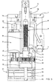
- a first embodiment of the invention comprises a body 1 machined to receive permanently and fix by means suitable an electric motor 2 for actuation and a set 3 of drive connected to a threaded actuating rod 4, capable of actuating the movement of a pilot assembly 5, for positioning a bodywork part not shown.
- the body 1 has an upper face for mounting on a fixed frame not shown and has a form of housing receiving the electric motor 2 powered by a power and signal transmission cable 6, connected to a source energy or external control via an electrical outlet 7 transmission of power and of measurement and control signals.
- the shaft end 8 of the electric motor 2 receives a pinion pinion 9 capable of mesh with a toothed wheel 10 of the actuation assembly 3.
- the assembly actuator 3 comprises the threaded rod 4 secured to an enlarged portion 11 receiving permanently the toothed wheel 10.
- the enlarged portion 11 is mounted in two bearings 12 and 13 arranged on either side of the toothed wheel 10.
- the mobile assembly 5 "pilot carrier” includes an internal thread thread trapezoidal 14 cooperating with the threaded rod 4 drive.
- the lower part of the pilot carrier assembly 5 comprising the internal thread 14 also carries a member 15 anti-rotation, ensuring the linear movement of the pilot carrier assembly 5 during relative screwing of the threaded rod 4 in the thread 14 forming a movable nut in translation.
- a sliding sliding bearing 16 is provided for translation in the direction of the arrow T of the pilot carrier assembly 5.
- the electric motor 2 is mounted head to tail relative to the assembly pilot carrier 5, which it ensures the displacement.
- the electric motor 2 has a second end of the shaft exceeding 18 inserted in an optical or incremental encoder 19 allowing piloting continuously of the motor, and consequently of the translational displacement T of the pilot carrier assembly 5.
- this provision allows also to actuate the pilot carrier assembly 5 directly, or through the actuating assembly 3, subjected to a mechanical action on one end 20 accessible from outside the body 1 without dismantling the body 1.
- the end 20 may for example have a conformation in the form of a screw, in hollow hexagonal imprint or any other hollow or raised imprint suitable for allow control, manual or by means of an external tool, of the assembly 3 and of the pilot carrier 5 able to move in translation in the direction of the arrow T.
- this arrangement makes it possible in this case to order simultaneously the rotation of the rotor of motor 2, and consequently the angular position of motor 2 linked in rotation to the movement of the assembly 3.
- This arrangement therefore allows computer control of device according to the invention in combination with other means usable in automotive bodywork, safely, because the instantaneous position of the driver carrier corresponds to a single corresponding position of the motor 2 which can be interpreted by a computer, programmable logic controller or "intelligent" means equivalent.
- the lower plate 1b of the body 1 of the device is replaced by a box 21 containing cards and control circuits 22 to 24.
- the control boards or circuits 22 to 24 make it possible to constitute the device according to the invention as an "intelligent" device, directly addressable by a computer or by a programmable controller.
- socket 7 is disposed on the side of the control cards 22, 24 which advantageously include in this case an additional power card.
- another embodiment of the invention comprises a body 31 machined to receive a mobile assembly and a motor electric 32.
- the electric motor 32 drives by a gear a toothed nut 33 outwardly.
- the nut 33 mobile in rotation moves a threaded rod 34 mobile in translation which allows to move in translation a set of centering and tightening similar to that described in French patent application 98.09549 no published July 27, 1998.
- the threaded rod 34 by moving thus acts in the manner of a piston causing a displacement in the opposite direction of the centering and Tightening.
- the head 34a is articulated with a large clearance on a through axis 35 of which is fixed to a bracket 36, mounted on a pin 37 fixed in the body, and bearing also a connecting rod 38 articulated at 39 on the bracket 36.
- the connecting rod 38 has at its end opposite its hinge pin 39 a axis 40 for controlling the input and output of the gripping members 41 of the device.
- the electrical means 32 drive is mounted head to tail relative to the actuating member 34 which causes the mechanism of the device to operate.
- This arrangement makes it possible to obtain a compact, simple and economical, while ensuring self-locking in the event of a power failure electric or untimely shutdown.
- the actuating part driven in rotation 33 in bearings such as bearings 12 and 13 of FIGS. 1 and 2
- the invention can also be applied to devices known as name of "tightenings", in which an arm is actuated to come to tighten or maintain a bodywork part or an element useful for automobile construction.
- the compactness of the device also makes it possible to envisage the reduction of manufacturing references, by designing a modular body capable of receiving a motor electric 2, or 32, standard, which can be fitted with training equipment, and possibly an "intelligent" control unit, while a reservation is designed to mount mechanisms ensuring clamping, positioning, holding or another mode of immobilization useful for automobile manufacturing.
- Head-to-tail mounting is particularly advantageous, as is the provision consisting of providing an "intelligent" box, which can be adapted with simple modifications to a modular device body according to the invention.
Landscapes
- Engineering & Computer Science (AREA)
- Mechanical Engineering (AREA)
- Connection Of Plates (AREA)
- Lock And Its Accessories (AREA)
- Automobile Manufacture Line, Endless Track Vehicle, Trailer (AREA)
- Manipulator (AREA)
- Automatic Assembly (AREA)
- Gear Transmission (AREA)
- Transmission Devices (AREA)
- Power-Operated Mechanisms For Wings (AREA)
- Lighting Device Outwards From Vehicle And Optical Signal (AREA)
Applications Claiming Priority (2)
| Application Number | Priority Date | Filing Date | Title |
|---|---|---|---|
| FR0001712 | 2000-02-11 | ||
| FR0001712A FR2804929B1 (fr) | 2000-02-11 | 2000-02-11 | Dispositif de centrage et de serrage, notamment de pieces pour carrosserie automobile |
Publications (2)
| Publication Number | Publication Date |
|---|---|
| EP1123779A1 true EP1123779A1 (de) | 2001-08-16 |
| EP1123779B1 EP1123779B1 (de) | 2006-11-15 |
Family
ID=8846901
Family Applications (1)
| Application Number | Title | Priority Date | Filing Date |
|---|---|---|---|
| EP01400326A Expired - Lifetime EP1123779B1 (de) | 2000-02-11 | 2001-02-09 | Vorrichtung zum Zentrieren und Spannen, vorzugsweise von Fahrzeugkarosserie Teilen |
Country Status (7)
| Country | Link |
|---|---|
| US (1) | US6695359B2 (de) |
| EP (1) | EP1123779B1 (de) |
| JP (1) | JP2001294395A (de) |
| AT (1) | ATE345195T1 (de) |
| DE (1) | DE60124438T2 (de) |
| ES (1) | ES2275632T3 (de) |
| FR (1) | FR2804929B1 (de) |
Cited By (9)
| Publication number | Priority date | Publication date | Assignee | Title |
|---|---|---|---|---|
| WO2005002793A1 (en) * | 2003-06-02 | 2005-01-13 | Norgren Automotive, Inc. | Rotatably adjustable apparatus for locating a workpiece |
| US6971498B2 (en) | 2003-03-28 | 2005-12-06 | Univer S.P.A. | Centering device with cleaning means |
| EP1702721A1 (de) | 2005-03-17 | 2006-09-20 | UNIVER S.p.A. | Spann- und Zentriervorrichtung mit hakenförmigem Spannstück |
| EP1702719A1 (de) | 2005-03-17 | 2006-09-20 | UNIVER S.p.A. | Unterflurspanner für Werkstücke mit einem hakenförmigen Spannelement |
| EP1878539A1 (de) * | 2006-06-26 | 2008-01-16 | UNIVER S.p.A. | Klemm- und/oder Zentriervorrichtung für Werkstücke, mit manuell einstellbaren Arbeitspositionen |
| CN106678287A (zh) * | 2015-11-11 | 2017-05-17 | 衡阳市锦泰工具有限公司 | 一种可换挡变速汽车板簧螺栓拆装器离合机构 |
| CN106903635A (zh) * | 2017-05-04 | 2017-06-30 | 安徽航大智能科技有限公司 | 一种应用于薄壁套件夹紧的高精度自定心夹紧机构 |
| IT202000003805A1 (it) * | 2020-02-24 | 2021-08-24 | Pneumax S P A | Unita’ di attuazione del tipo a leva articolata o a camma ad azionamento elettrico |
| IT202300009690A1 (it) | 2023-05-15 | 2024-11-15 | Pneumax S P A | Unita’ di centraggio con gruppo antirotazione |
Families Citing this family (38)
| Publication number | Priority date | Publication date | Assignee | Title |
|---|---|---|---|---|
| ITMI20012240A1 (it) * | 2001-10-25 | 2003-04-25 | Luciano Migliori | Dispositivo di bloccaggio con controllo ottico di posizione |
| ITMI20012311A1 (it) | 2001-11-05 | 2003-05-05 | Luciano Migliori | Dispositivo di bloccaggio azionato elettricamente |
| FR2837118B1 (fr) * | 2002-03-18 | 2004-08-06 | Bema Ingenierie | Tete de bridage comportant un pilote de centrage a griffes de serrage retractables |
| JP2004042886A (ja) * | 2002-05-20 | 2004-02-12 | Nissan Motor Co Ltd | 車体とフレームの組付方法および組付用治具 |
| US6786478B2 (en) * | 2002-07-10 | 2004-09-07 | Welker Bearing Company | Locating assembly having an extendable clamping finger |
| ITMI20021756A1 (it) * | 2002-08-02 | 2004-02-03 | Luciano Migliori | Dispositivo di aggancio per pezzi da lavorare. |
| US7184238B1 (en) * | 2002-10-07 | 2007-02-27 | Storage Technology Corporation | Track impedance anomaly detection in an automated data storage library |
| ITMI20031454A1 (it) * | 2003-07-16 | 2005-01-17 | Univer Spa | Dispositivo di aggancio compatto per pezzi da lavorare |
| US7815176B2 (en) | 2003-09-11 | 2010-10-19 | Phd, Inc. | Lock mechanism for pin clamp assembly |
| US7516948B2 (en) * | 2004-04-02 | 2009-04-14 | Phd, Inc. | Pin clamp accessories |
| US7182326B2 (en) * | 2004-04-02 | 2007-02-27 | Phd, Inc. | Pin clamp |
| US7448607B2 (en) * | 2004-12-15 | 2008-11-11 | Phd, Inc. | Pin clamp assembly |
| ITMI20050074U1 (it) * | 2005-03-07 | 2006-09-08 | Univer Spa | Dispositivo di ritegno per pezzi da lavorare con unita'elettronica di controllo rimovibile |
| DE102006002000A1 (de) * | 2006-01-16 | 2007-07-19 | Robert Bosch Gmbh | Umsetzeinrichtung mit wenigstens einem Fangstift |
| US20070267795A1 (en) * | 2006-02-06 | 2007-11-22 | Parag Patwardhan | Pin clamp transfer assembly and method of transferring a workpiece |
| US20080000068A1 (en) * | 2006-06-28 | 2008-01-03 | Savoy Mark A | Adjustment of work pallets for vehicle body assembly lines |
| DE102007022009B4 (de) * | 2007-05-08 | 2009-03-19 | Schenck Rotec Gmbh | Aufnahmevorrichtung zum Auswuchten von Doppelkupplungen |
| MX2009014026A (es) * | 2007-06-19 | 2010-03-10 | Phd Inc | Ensamble de abrazadera de perno. |
| US8366085B2 (en) * | 2007-06-19 | 2013-02-05 | Phd, Inc. | Pin locating assembly |
| JP4737456B2 (ja) | 2007-11-22 | 2011-08-03 | Smc株式会社 | グリッパ機構 |
| WO2009155261A1 (en) * | 2008-06-18 | 2009-12-23 | Phd, Inc. | Strip off pin clamp |
| KR101173765B1 (ko) | 2010-07-15 | 2012-08-13 | 한전케이피에스 주식회사 | 밸브 스프링 분해 조립 장치 |
| JP5170225B2 (ja) * | 2010-12-10 | 2013-03-27 | 株式会社安川電機 | ワーク位置決め装置およびそれを用いた生産システム |
| US9156510B2 (en) * | 2012-10-17 | 2015-10-13 | Btm Company Llc | Clamp mounting system |
| US10695060B2 (en) * | 2017-09-01 | 2020-06-30 | RevMedica, Inc. | Loadable power pack for surgical instruments |
| US10966720B2 (en) | 2017-09-01 | 2021-04-06 | RevMedica, Inc. | Surgical stapler with removable power pack |
| US11331099B2 (en) | 2017-09-01 | 2022-05-17 | Rev Medica, Inc. | Surgical stapler with removable power pack and interchangeable battery pack |
| EP3505299A4 (de) * | 2017-09-28 | 2020-03-18 | Energium Co., Ltd. | Elektrisch betriebene spannvorrichtung |
| US12279771B2 (en) | 2019-07-19 | 2025-04-22 | RevMedica, Inc. | Power pack for activating surgical instruments and providing user feedback |
| EP3998960A4 (de) | 2019-07-19 | 2022-12-14 | Revmedica, Inc. | Chirurgisches klammergerät mit abnehmbarem netzteil |
| US12279770B2 (en) | 2019-07-19 | 2025-04-22 | RevMedica, Inc. | Power pack for activating surgical instruments and providing user feedback |
| US12290257B2 (en) | 2019-07-19 | 2025-05-06 | RevMedica, Inc. | Surgical clip applier with removable power pack |
| DE102020003577B3 (de) * | 2020-06-16 | 2021-06-10 | Olaf und André Tünkers GbR (vertretungsberechtigter Gesellschafter: Dipl.-Ing. Olaf Tünkers, 40883 Ratingen) | Unterbodenspanner mit Kniehebelgelenk und Kulissenführung, zur Verwendung im Karosseriebau der Kfz-lndustrie |
| ES2913373B2 (es) * | 2020-12-01 | 2022-10-03 | Seat Sa | Dispositivo de sujecion y centrado de piezas en sistemas de produccion, sistema de produccion que lo contiene y metodo de funcionamiento de dicho dispositivo |
| EP4301247A4 (de) | 2021-03-01 | 2025-01-22 | Revmedica, Inc. | Netzteil zur aktivierung chirurgischer instrumente |
| CN114161363A (zh) * | 2021-12-20 | 2022-03-11 | 国网河南省电力公司洛阳供电公司 | 通用型变压器呼吸器拆装工具 |
| EP4522037A1 (de) | 2022-05-13 | 2025-03-19 | Revmedica, Inc. | Netzteil zur aktivierung chirurgischer instrumente und bereitstellung von benutzerfeedback |
| DE102023116419A1 (de) * | 2023-06-22 | 2024-12-24 | Andreas Maier Gmbh & Co. Kg | Spannvorrichtung |
Citations (7)
| Publication number | Priority date | Publication date | Assignee | Title |
|---|---|---|---|---|
| EP0243599A2 (de) * | 1986-04-23 | 1987-11-04 | Josef-Gerhard Tünkers | Kniehebelspannvorrichtung |
| EP0348802A2 (de) * | 1988-06-29 | 1990-01-03 | Eaton Corporation | Regler für eine elektrische Spannvorrichtung |
| FR2755049A1 (fr) * | 1996-10-25 | 1998-04-30 | Ragonot | Serrage pilote compact |
| EP0919338A2 (de) * | 1994-06-06 | 1999-06-02 | Incoe Corporation | Elektrische Spannvorrichtung für eine Form |
| FR2776858A1 (fr) * | 1998-03-27 | 1999-10-01 | Genus Technologies | Dispositif de maintien, de positionnement, ou de serrage, a actionnement electrique |
| FR2781176A1 (fr) * | 1998-07-20 | 2000-01-21 | Patrice Vouland | Pilote auto serrant |
| EP0976482A1 (de) * | 1998-07-27 | 2000-02-02 | Genus Technologies | Zentrier- und Spannvorrichtung, insbesondere für Teile beim Wagenaufbau |
Family Cites Families (11)
| Publication number | Priority date | Publication date | Assignee | Title |
|---|---|---|---|---|
| US3704879A (en) * | 1971-03-29 | 1972-12-05 | Kyoritsu Mfg Co Ltd | Electric vise |
| IT1078818B (it) * | 1976-05-21 | 1985-05-08 | Cremona Angelo | Dispositivo per il fissaggio del tronco conganci di lunghezze diverse e per il comando a distanza della fuoriuscita o del rientro di detti ganci dalla,e rispettivamente nella tavola di supporto verticale o pressocche'verticale di una traciatrice |
| US4635911A (en) * | 1985-08-30 | 1987-01-13 | Lovrenich Rodger T | Motorized over center clamp |
| US4723767A (en) * | 1986-08-08 | 1988-02-09 | De-Sta-Co Division, Dover Resources, Inc. | Rotary powered linear actuated clamp |
| US4700936A (en) * | 1986-08-26 | 1987-10-20 | Lamb Technicon Corp. | Clamp mechanism |
| US4770401A (en) * | 1986-09-08 | 1988-09-13 | Donaldson Humel J | Powered C-clamp apparatus |
| JPH0613787Y2 (ja) * | 1987-12-10 | 1994-04-13 | 日産自動車株式会社 | ワーク位置決め装置 |
| US4971301A (en) * | 1987-12-16 | 1990-11-20 | Yang Tai Her | Vise |
| US5915898A (en) * | 1997-07-16 | 1999-06-29 | Pfister; Dennis M. | Adapter arm for machine tools |
| DE29718643U1 (de) * | 1997-10-21 | 1997-12-11 | Tünkers Maschinenbau GmbH, 40880 Ratingen | Druckmittelbetätigbare kombinierte Zentrier- und Spannvorrichtung, insbesondere zur Verwendung im Karosseriebau der Kfz-Industrie |
| JP2001105332A (ja) * | 1999-10-01 | 2001-04-17 | Smc Corp | 電動クランプ装置 |
-
2000
- 2000-02-11 FR FR0001712A patent/FR2804929B1/fr not_active Expired - Fee Related
-
2001
- 2001-02-09 JP JP2001033033A patent/JP2001294395A/ja active Pending
- 2001-02-09 DE DE60124438T patent/DE60124438T2/de not_active Expired - Fee Related
- 2001-02-09 EP EP01400326A patent/EP1123779B1/de not_active Expired - Lifetime
- 2001-02-09 AT AT01400326T patent/ATE345195T1/de not_active IP Right Cessation
- 2001-02-09 ES ES01400326T patent/ES2275632T3/es not_active Expired - Lifetime
- 2001-02-12 US US09/780,521 patent/US6695359B2/en not_active Expired - Fee Related
Patent Citations (7)
| Publication number | Priority date | Publication date | Assignee | Title |
|---|---|---|---|---|
| EP0243599A2 (de) * | 1986-04-23 | 1987-11-04 | Josef-Gerhard Tünkers | Kniehebelspannvorrichtung |
| EP0348802A2 (de) * | 1988-06-29 | 1990-01-03 | Eaton Corporation | Regler für eine elektrische Spannvorrichtung |
| EP0919338A2 (de) * | 1994-06-06 | 1999-06-02 | Incoe Corporation | Elektrische Spannvorrichtung für eine Form |
| FR2755049A1 (fr) * | 1996-10-25 | 1998-04-30 | Ragonot | Serrage pilote compact |
| FR2776858A1 (fr) * | 1998-03-27 | 1999-10-01 | Genus Technologies | Dispositif de maintien, de positionnement, ou de serrage, a actionnement electrique |
| FR2781176A1 (fr) * | 1998-07-20 | 2000-01-21 | Patrice Vouland | Pilote auto serrant |
| EP0976482A1 (de) * | 1998-07-27 | 2000-02-02 | Genus Technologies | Zentrier- und Spannvorrichtung, insbesondere für Teile beim Wagenaufbau |
Cited By (12)
| Publication number | Priority date | Publication date | Assignee | Title |
|---|---|---|---|---|
| US6971498B2 (en) | 2003-03-28 | 2005-12-06 | Univer S.P.A. | Centering device with cleaning means |
| WO2005002793A1 (en) * | 2003-06-02 | 2005-01-13 | Norgren Automotive, Inc. | Rotatably adjustable apparatus for locating a workpiece |
| US7490532B2 (en) | 2003-06-02 | 2009-02-17 | Norgren Automotive, Inc. | Rotatably adjustable apparatus for locating a workpiece |
| EP1702721A1 (de) | 2005-03-17 | 2006-09-20 | UNIVER S.p.A. | Spann- und Zentriervorrichtung mit hakenförmigem Spannstück |
| EP1702719A1 (de) | 2005-03-17 | 2006-09-20 | UNIVER S.p.A. | Unterflurspanner für Werkstücke mit einem hakenförmigen Spannelement |
| EP1878539A1 (de) * | 2006-06-26 | 2008-01-16 | UNIVER S.p.A. | Klemm- und/oder Zentriervorrichtung für Werkstücke, mit manuell einstellbaren Arbeitspositionen |
| CN106678287A (zh) * | 2015-11-11 | 2017-05-17 | 衡阳市锦泰工具有限公司 | 一种可换挡变速汽车板簧螺栓拆装器离合机构 |
| CN106903635A (zh) * | 2017-05-04 | 2017-06-30 | 安徽航大智能科技有限公司 | 一种应用于薄壁套件夹紧的高精度自定心夹紧机构 |
| CN106903635B (zh) * | 2017-05-04 | 2018-07-24 | 安徽航大智能科技有限公司 | 一种应用于薄壁套件夹紧的高精度自定心夹紧机构 |
| IT202000003805A1 (it) * | 2020-02-24 | 2021-08-24 | Pneumax S P A | Unita’ di attuazione del tipo a leva articolata o a camma ad azionamento elettrico |
| IT202300009690A1 (it) | 2023-05-15 | 2024-11-15 | Pneumax S P A | Unita’ di centraggio con gruppo antirotazione |
| DE112024001640T5 (de) | 2023-05-15 | 2026-03-12 | Pneumax S.P.A. | Zentriereinheit mit anti-rotationsgruppe |
Also Published As
| Publication number | Publication date |
|---|---|
| US6695359B2 (en) | 2004-02-24 |
| ES2275632T3 (es) | 2007-06-16 |
| FR2804929A1 (fr) | 2001-08-17 |
| DE60124438D1 (de) | 2006-12-28 |
| JP2001294395A (ja) | 2001-10-23 |
| ATE345195T1 (de) | 2006-12-15 |
| DE60124438T2 (de) | 2007-09-06 |
| US20010013164A1 (en) | 2001-08-16 |
| FR2804929B1 (fr) | 2002-05-31 |
| EP1123779B1 (de) | 2006-11-15 |
Similar Documents
| Publication | Publication Date | Title |
|---|---|---|
| EP1123779A1 (de) | Vorrichtung zum Zentrieren und Spannen, vorzugsweise von Fahrzeugkarosserie Teilen | |
| FR2541644A1 (fr) | Bloc de direction pour vehicules, comprenant un tableau de bord integre au moyen du volant de direction | |
| FR2545624A1 (fr) | Dispositif d'actionnement electromecanique compact | |
| FR3016011A1 (fr) | Actionneur entraine par pignon a glissiere axiale, et frein a tambour et dispositif de freinage ainsi equipes | |
| FR2549432A1 (fr) | Ensemble de direction assistee de vehicule | |
| EP2148413B1 (de) | Integriertes lineares elektrisches Stellglied | |
| FR2652318A1 (fr) | Retroviseur exterieur pour vehicule. | |
| FR2545180A1 (fr) | Mecanisme de transmission, en particulier pour essuie-glace de vehicules | |
| FR2622945A1 (fr) | Mecanisme d'entrainement debrayable pour couronne tournante | |
| FR3016016A1 (fr) | Motoreducteur avec moteur electrique adaptable pour actionneur de frein a tambour | |
| EP1066672B1 (de) | Vorrichtung zum halten, positionieren oder spannen | |
| EP4259493B1 (de) | Aktuator mit integrierter feststellbremse | |
| FR2596096A1 (fr) | Dispositif d'entrainement d'une tige de commande d'actionneur de serrure notamment de serrure de porte de vehicule automobile, et serrure equipee d'un tel dispositif | |
| EP0605283B1 (de) | Mit einem Lagesensor versehene elektrische Schraubenwinde | |
| EP1329292A1 (de) | Spannvorrichtung, insbesondere für Fahrzeugkarosserieteile | |
| EP0843248B1 (de) | Entkuppelbares Aktivierungssystem eines funktionellen Kraftfahrzeugelementes | |
| FR2886262A1 (fr) | Dispositif electrique de freinage de stationnement pour vehicule automobile, et vehicule automobile correspondant | |
| EP1563205B1 (de) | Aktuator zum verschieben eines elements | |
| EP2037143B1 (de) | Perfektionierte Steuervorrichtung | |
| EP0967050A2 (de) | Positionier-, Halte- oder Spannvorrichtung | |
| FR2525285A1 (fr) | Turbine avec rotor a pales orientables | |
| EP4559767A1 (de) | Scheibenbremse, insbesondere für ein kraftfahrzeug | |
| FR2824581A1 (fr) | Dispositif d'actionnement en rotation d'un organe a actionner de vehicule automobile | |
| FR3063585A1 (fr) | Dispositif d’actionnement a deux actionneurs | |
| EP2391836A1 (de) | Stellglied |
Legal Events
| Date | Code | Title | Description |
|---|---|---|---|
| PUAI | Public reference made under article 153(3) epc to a published international application that has entered the european phase |
Free format text: ORIGINAL CODE: 0009012 |
|
| AK | Designated contracting states |
Kind code of ref document: A1 Designated state(s): AT BE CH CY DE DK ES FI FR GB GR IE IT LI LU MC NL PT SE TR |
|
| AX | Request for extension of the european patent |
Free format text: AL;LT;LV;MK;RO PAYMENT 20010217;SI PAYMENT 20010217 |
|
| 17P | Request for examination filed |
Effective date: 20020202 |
|
| AKX | Designation fees paid |
Free format text: AT BE CH CY DE DK ES FI FR GB GR IE IT LI LU MC NL PT SE TR |
|
| AXX | Extension fees paid |
Free format text: RO PAYMENT 20010217;SI PAYMENT 20010217 |
|
| 17Q | First examination report despatched |
Effective date: 20040908 |
|
| GRAP | Despatch of communication of intention to grant a patent |
Free format text: ORIGINAL CODE: EPIDOSNIGR1 |
|
| GRAS | Grant fee paid |
Free format text: ORIGINAL CODE: EPIDOSNIGR3 |
|
| GRAA | (expected) grant |
Free format text: ORIGINAL CODE: 0009210 |
|
| AK | Designated contracting states |
Kind code of ref document: B1 Designated state(s): AT BE CH CY DE DK ES FI FR GB GR IE IT LI LU MC NL PT SE TR |
|
| AX | Request for extension of the european patent |
Extension state: RO SI |
|
| PG25 | Lapsed in a contracting state [announced via postgrant information from national office to epo] |
Ref country code: IE Free format text: LAPSE BECAUSE OF FAILURE TO SUBMIT A TRANSLATION OF THE DESCRIPTION OR TO PAY THE FEE WITHIN THE PRESCRIBED TIME-LIMIT Effective date: 20061115 Ref country code: FI Free format text: LAPSE BECAUSE OF FAILURE TO SUBMIT A TRANSLATION OF THE DESCRIPTION OR TO PAY THE FEE WITHIN THE PRESCRIBED TIME-LIMIT Effective date: 20061115 Ref country code: AT Free format text: LAPSE BECAUSE OF FAILURE TO SUBMIT A TRANSLATION OF THE DESCRIPTION OR TO PAY THE FEE WITHIN THE PRESCRIBED TIME-LIMIT Effective date: 20061115 Ref country code: NL Free format text: LAPSE BECAUSE OF FAILURE TO SUBMIT A TRANSLATION OF THE DESCRIPTION OR TO PAY THE FEE WITHIN THE PRESCRIBED TIME-LIMIT Effective date: 20061115 |
|
| RAP1 | Party data changed (applicant data changed or rights of an application transferred) |
Owner name: GENUS TECHNOLOGIES |
|
| REG | Reference to a national code |
Ref country code: GB Ref legal event code: FG4D Free format text: NOT ENGLISH |
|
| REG | Reference to a national code |
Ref country code: CH Ref legal event code: EP |
|
| REF | Corresponds to: |
Ref document number: 60124438 Country of ref document: DE Date of ref document: 20061228 Kind code of ref document: P |
|
| REG | Reference to a national code |
Ref country code: IE Ref legal event code: FG4D Free format text: LANGUAGE OF EP DOCUMENT: FRENCH |
|
| PGFP | Annual fee paid to national office [announced via postgrant information from national office to epo] |
Ref country code: GB Payment date: 20070214 Year of fee payment: 7 |
|
| PG25 | Lapsed in a contracting state [announced via postgrant information from national office to epo] |
Ref country code: DK Free format text: LAPSE BECAUSE OF FAILURE TO SUBMIT A TRANSLATION OF THE DESCRIPTION OR TO PAY THE FEE WITHIN THE PRESCRIBED TIME-LIMIT Effective date: 20070215 Ref country code: SE Free format text: LAPSE BECAUSE OF FAILURE TO SUBMIT A TRANSLATION OF THE DESCRIPTION OR TO PAY THE FEE WITHIN THE PRESCRIBED TIME-LIMIT Effective date: 20070215 |
|
| PG25 | Lapsed in a contracting state [announced via postgrant information from national office to epo] |
Ref country code: MC Free format text: LAPSE BECAUSE OF NON-PAYMENT OF DUE FEES Effective date: 20070228 Ref country code: CH Free format text: LAPSE BECAUSE OF NON-PAYMENT OF DUE FEES Effective date: 20070228 Ref country code: LI Free format text: LAPSE BECAUSE OF NON-PAYMENT OF DUE FEES Effective date: 20070228 |
|
| GBT | Gb: translation of ep patent filed (gb section 77(6)(a)/1977) |
Effective date: 20070212 |
|
| PGFP | Annual fee paid to national office [announced via postgrant information from national office to epo] |
Ref country code: ES Payment date: 20070326 Year of fee payment: 7 |
|
| PG25 | Lapsed in a contracting state [announced via postgrant information from national office to epo] |
Ref country code: PT Free format text: LAPSE BECAUSE OF FAILURE TO SUBMIT A TRANSLATION OF THE DESCRIPTION OR TO PAY THE FEE WITHIN THE PRESCRIBED TIME-LIMIT Effective date: 20070416 |
|
| NLV1 | Nl: lapsed or annulled due to failure to fulfill the requirements of art. 29p and 29m of the patents act | ||
| REG | Reference to a national code |
Ref country code: ES Ref legal event code: FG2A Ref document number: 2275632 Country of ref document: ES Kind code of ref document: T3 |
|
| REG | Reference to a national code |
Ref country code: IE Ref legal event code: FD4D |
|
| PLBE | No opposition filed within time limit |
Free format text: ORIGINAL CODE: 0009261 |
|
| STAA | Information on the status of an ep patent application or granted ep patent |
Free format text: STATUS: NO OPPOSITION FILED WITHIN TIME LIMIT |
|
| REG | Reference to a national code |
Ref country code: CH Ref legal event code: PL |
|
| 26N | No opposition filed |
Effective date: 20070817 |
|
| BERE | Be: lapsed |
Owner name: GENUS TECHNOLOGIES Effective date: 20070228 |
|
| PG25 | Lapsed in a contracting state [announced via postgrant information from national office to epo] |
Ref country code: BE Free format text: LAPSE BECAUSE OF NON-PAYMENT OF DUE FEES Effective date: 20070228 |
|
| PGFP | Annual fee paid to national office [announced via postgrant information from national office to epo] |
Ref country code: IT Payment date: 20070622 Year of fee payment: 7 |
|
| PG25 | Lapsed in a contracting state [announced via postgrant information from national office to epo] |
Ref country code: GR Free format text: LAPSE BECAUSE OF FAILURE TO SUBMIT A TRANSLATION OF THE DESCRIPTION OR TO PAY THE FEE WITHIN THE PRESCRIBED TIME-LIMIT Effective date: 20070216 |
|
| PGFP | Annual fee paid to national office [announced via postgrant information from national office to epo] |
Ref country code: DE Payment date: 20080222 Year of fee payment: 8 |
|
| PGFP | Annual fee paid to national office [announced via postgrant information from national office to epo] |
Ref country code: FR Payment date: 20080227 Year of fee payment: 8 |
|
| GBPC | Gb: european patent ceased through non-payment of renewal fee |
Effective date: 20080209 |
|
| REG | Reference to a national code |
Ref country code: ES Ref legal event code: FD2A Effective date: 20080211 |
|
| PG25 | Lapsed in a contracting state [announced via postgrant information from national office to epo] |
Ref country code: GB Free format text: LAPSE BECAUSE OF NON-PAYMENT OF DUE FEES Effective date: 20080209 |
|
| PG25 | Lapsed in a contracting state [announced via postgrant information from national office to epo] |
Ref country code: ES Free format text: LAPSE BECAUSE OF NON-PAYMENT OF DUE FEES Effective date: 20080211 |
|
| PG25 | Lapsed in a contracting state [announced via postgrant information from national office to epo] |
Ref country code: CY Free format text: LAPSE BECAUSE OF FAILURE TO SUBMIT A TRANSLATION OF THE DESCRIPTION OR TO PAY THE FEE WITHIN THE PRESCRIBED TIME-LIMIT Effective date: 20061115 Ref country code: LU Free format text: LAPSE BECAUSE OF NON-PAYMENT OF DUE FEES Effective date: 20070209 Ref country code: IT Free format text: LAPSE BECAUSE OF NON-PAYMENT OF DUE FEES Effective date: 20080209 |
|
| PG25 | Lapsed in a contracting state [announced via postgrant information from national office to epo] |
Ref country code: TR Free format text: LAPSE BECAUSE OF FAILURE TO SUBMIT A TRANSLATION OF THE DESCRIPTION OR TO PAY THE FEE WITHIN THE PRESCRIBED TIME-LIMIT Effective date: 20061115 |
|
| REG | Reference to a national code |
Ref country code: FR Ref legal event code: ST Effective date: 20091030 |
|
| PG25 | Lapsed in a contracting state [announced via postgrant information from national office to epo] |
Ref country code: DE Free format text: LAPSE BECAUSE OF NON-PAYMENT OF DUE FEES Effective date: 20090901 |
|
| PG25 | Lapsed in a contracting state [announced via postgrant information from national office to epo] |
Ref country code: FR Free format text: LAPSE BECAUSE OF NON-PAYMENT OF DUE FEES Effective date: 20090302 |