EP1125523A1 - Eine aus einer Vielzahl von Schieberegalen gebildete Lagereinrichtung - Google Patents
Eine aus einer Vielzahl von Schieberegalen gebildete Lagereinrichtung Download PDFInfo
- Publication number
- EP1125523A1 EP1125523A1 EP01103948A EP01103948A EP1125523A1 EP 1125523 A1 EP1125523 A1 EP 1125523A1 EP 01103948 A EP01103948 A EP 01103948A EP 01103948 A EP01103948 A EP 01103948A EP 1125523 A1 EP1125523 A1 EP 1125523A1
- Authority
- EP
- European Patent Office
- Prior art keywords
- sliding
- storage device
- sliding shelves
- device formed
- shelves
- Prior art date
- Legal status (The legal status is an assumption and is not a legal conclusion. Google has not performed a legal analysis and makes no representation as to the accuracy of the status listed.)
- Granted
Links
Images
Classifications
-
- A—HUMAN NECESSITIES
- A47—FURNITURE; DOMESTIC ARTICLES OR APPLIANCES; COFFEE MILLS; SPICE MILLS; SUCTION CLEANERS IN GENERAL
- A47B—TABLES; DESKS; OFFICE FURNITURE; CABINETS; DRAWERS; GENERAL DETAILS OF FURNITURE
- A47B53/00—Cabinets or racks having several sections one behind the other
- A47B53/02—Cabinet systems, e.g. consisting of cabinets arranged in a row with means to open or close passages between adjacent cabinets
Definitions
- the invention relates to a formed from a plurality of sliding shelves Storage facility in which the sliding shelves are in the floor or a ceiling of a Building-laid tracks are movable, and with each sliding shelf equipped with an electric motor drive and a safety circuit is.
- the storage facility in question is used to store objects of all kinds kind of storage.
- the special advantage of sliding shelves is that that the largest possible storage space is available in the smallest space, since the Sliding shelves can be strung together without space. It just has to be ensured be that they can be operated in such a way that a person or that several people are between two sliding shelves can move.
- a wide variety of objects can be placed on the sliding shelves be stored, for example items that are kept in a museum and Be presented to visitors, as well as documentation in the form of books and the like.
- the sliding shelves can still be moved manually by the shaft mounted and driven in the lower area via a chain drive is rotated.
- the chain drive is manually by means of a crank or a handwheel, with the crank or the handwheel on one Side of the sliding shelf is mounted at such a height that it or that it in an ergonomically adjusted height.
- the disadvantage of these storage facilities is that for moving apart two adjacent sliding shelves either the sliding shelves to the left or right of it are also manually must be moved so that the handling is to be regarded as cumbersome.
- the invention has for its object one of a variety of sliding shelves existing storage facility of the type described in more detail in constructive the simplest way to design so that a high security standard is met will and that existing storage facilities can be retrofitted, and that the system is also easy to maintain and repair.
- each sliding shelf is equipped with at least one electric motor drive, the output member with the one at a distance from the underside of the sliding shelf Input member of the drive train is coupled.
- the electromotive Drive which essentially consists of a drive motor and a speed of rotation Motor shaft reducing gear reducer exists, arranged on the side part it is extremely accessible so that it is easy to maintain and repair.
- the distance to the ground corresponds to the distance of the pivot point of the crank or the handwheel, which was arranged at an ergonomically favorable height.
- the storage facility can consist of a relative high number of sliding shelves consist, for example, of more than thirty Sliding shelves. Since the individual sliding shelves are usually loaded or be discharged, is provided in a further embodiment to increase safety, that the electric motor of the electromotive drive is a direct current motor which can be acted upon by a DC safety voltage.
- the safety DC voltage can be 24 or 42 V, for example.
- the DC motors can still be from the power supply network with a voltage of 220 V. feed if at least one transformer is in the power supply on the input side and at least one rectifier device are installed.
- the power supply The electric motors become particularly simple when the storage facility is used for power supply at least one preferably two-pole busbar is assigned.
- This busbar extends over the entire length of the storage facility, so that current is conducted to the individual drive motors via current collectors can. There is therefore no need for cables or lines that are due to the necessary mobility after a certain operating time could.
- one or more sliding shelves can be arranged in a particularly simple manner between existing sliding shelves at one point or at several Places are subsequently placed in between without the power supply being adjusted must become.
- the busbar also only with the safety direct voltage is applied, it is provided that they are in the upper or lower region the sliding shelves are arranged, and that the power rail is a transformer and a rectifier device is connected upstream.
- the arrangement of the Busbar above the sliding shelves has the advantage that normally none Touch when loading or unloading the shelves.
- Each sliding shelf is assigned its own control unit, which means that Susceptibility to interference is reduced.
- the control units all sliding shelves by at least one control cable or wirelessly are communicatively connected. This is a transfer and a Exchange of data possible.
- the sliding shelf is the so-called master function if its drive motor is operated. Through communication it is then achieved that the two sides move the sliding shelves of the material away from it, i.e. are moved in opposite directions.
- These functional processes are controlled by at least one microprocessor.
- the operating system of this microprocessor is stored in a read-only memory in such a way that it can be deleted and is then reprogrammable.
- a read-only memory is in the Electronics called Eprom.
- the signals are wireless, preferably via a Infrared radiation or by radio control regardless of the supply voltage he follows.
- each sliding shelf For easy operation of each sliding shelf it is provided that on each Sliding shelf an actuator, for example by a button or arranged wirelessly for switching the electric motor drive on and off is. Because often the filed objects are sorted according to a scheme a corresponding note is attached to each sliding shelf. As soon as the right sliding shelf is found, the procedure of the left and right sliding shelves can be initiated without the person would have to go to a central control unit. This can be done in further stages of expansion but also by radio control or by a warehouse management computer respectively. The communication-capable connection between the individual control units is switched so that when switching on a certain electromotive Drive the control units of the remaining sliding shelves so controlled are that depending on the position of the activated sliding shelf in one of the possible shooting directions.
- an overcurrent relay is arranged as an anti-lock device such that when The drive in operation is exceeding a predetermined current or the drives in operation can be stopped.
- This overcurrent relay is usually used in combination with the safety mat. However, it not only serves to protect people, but also as overload protection, if there are obstacles within the displacement path or if there are obstacles to be traversed Sliding shelf is covered or tilted. When turning off an on Drive or switching off several drives due to the overcurrent relay takes place, it is useful if after turning off the direction of rotation of the respective electric motor drive is reversible, so that the shelf then is moved against the previous direction, so that for example an obstacle can be removed. To further increase security, it is too still possible that in a space between the floor or ceiling of the Building and the bottom of the sliding shelf one or more buttons, preferably one or more light barriers are installed so that in the event of an obstacle the drives in operation can be switched off.
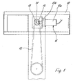
- FIG. 1 shows the electromotive drives mounted on the outside of a sliding shelf in a side view, highly schematic.
- a flat housing 10 On the side wall of a sliding shelf, not shown, is a flat housing 10 attached, which is closed by a lid when using the storage facility is.
- a shaft 11 is rotatably supported in the side wall of the sliding shelf, which forms the input member of a drive train 12 to the sliding shelf to move left and right.
- the drive is not shown because it belongs to the general state of the art.
- a crank or handwheel is rotatably mounted on the shaft 11, so that the sliding shelf can be moved to the left and right by hand.
- a bevel gear 13 On the shaft 11 is a bevel gear 13 rotatably mounted, which with a bevel gear 14 is engaged, which rotatably on the output pin of an electromotive Drive 15 is placed.
- the electric motor drive 15 consists of a DC motor 15a and a reduction gear 15b.
- the power supply of the DC motor 15a takes place from one in the upper area busbar extending all sliding shelves. Every sliding shelf is not with one Control unit shown equipped that communicatively linked with each other are.
- the invention is not based on the illustrated embodiment limited. It is essential that the sliding shelves operated by hand can be retrofitted with the electric motor drives 15 and the controls are, and that DC motors are used as the drive.
Landscapes
- Warehouses Or Storage Devices (AREA)
- Drawers Of Furniture (AREA)
- Sliding-Contact Bearings (AREA)
- Vibration Prevention Devices (AREA)
- Electric Cable Arrangement Between Relatively Moving Parts (AREA)
Abstract
Description
Claims (18)
- Eine aus einer Vielzahl von Schieberegalen gebildete Lagereinrichtung, bei der die Schieberegale auf im Boden oder einer Decke eines Gebäudes verlegten Laufschienen verfahrbar sind, und jedes Schieberegal mit einem elektromotorischen Antrieb und einer Sicherheitsschalteinrichtung ausgestattet ist, dadurch gekennzeichnet, daß zumindest ein Seitenteil jedes Schieberegals mit wenigstens einem elektromotorischen Antrieb ausgestattet ist, dessen Abtriebsglied mit dem in einem Abstand zur Unterseite des Schieberegals angeordneten Eingangsglied des Antriebszuges (12) gekoppelt ist.
- Eine aus einer Vielzahl von Schieberegalen gebildete Lagereinrichtung nach Anspruch 1, dadurch gekennzeichnet, daß der Elektromotor (15a) des elektromotorischen Antriebes (15) ein Gleichstrommotor ist, der mit einer Sicherheitsgleichspannung beaufschlagbar ist.
- Eine aus einer Vielzahl von Schieberegalen gebildete Lagereinrichtung nach Anspruch 1 oder 2, dadurch gekennzeichnet, daß der Lagereinrichtung zur Stromversorgung der elektromotorischen Antriebe (15) wenigstens eine vorzugsweise zweipolige Stromschiene zugeordnet ist.
- Eine aus einer Vielzahl von Schieberegalen gebildete Lagereinrichtung nach Anspruch 3, dadurch gekennzeichnet, daß die Stromschienen in dem oberen oder unteren Bereich der Schieberegale angeordnet sind, und daß jeder Stromschiene ein Transformator und eine Gleichrichterschalteinrichtung vorgeschaltet ist.
- Eine aus einer Vielzahl von Schieberegalen gebildete Lagereinrichtung nach einem oder mehreren der vorhergehenden Ansprüche 1 bis 4, dadurch gekennzeichnet, daß jedes Schieberegal mit einer eigenen Steuereinheit ausgerüstet ist.
- Eine aus einer Vielzahl von Schieberegalen gebildete Lagereinrichtung nach einem oder mehreren der vorhergehenden Ansprüche 1 bis 5, dadurch gekennzeichnet, daß die Funktionsabläufe aller Schieberegale der Lagereinrichtung durch wenigstens einen Mikroprozessor steuerbar sind.
- Eine aus einer Vielzahl von Schieberegalen gebildete Lagereinrichtung nach Anspruch 6, dadurch gekennzeichnet, daß das Betriebssystem des Mikroprozessors in einem Festwertspeicher derart speicherbar ist, daß es löschbar und anschließend neu programmierbar ist.
- Eine aus einer Vielzahl von Schieberegalen gebildete Lagereinrichtung nach einem oder mehreren der vorgehenden Ansprüche 5 bis 7, dadurch gekennzeichnet, daß die Steuereinheiten aller Schieberegale durch eine Steuerkabel und/oder drahtlos kommunizierend miteinander verbunden sind.
- Eine aus einer Vielzahl von Schieberegalen gebildete Lagereinrichtung gebildete Lagereinrichtung nach Anspruch 8, dadurch gekennzeichnet, daß zum Datenaustausch zwischen den Steuereinheiten der Schieberegale durch Infrarotstrahlung oder durch eine Funksteuerung unabhängig von der Versorgungsspannung erfolgt.
- Eine aus einer Vielzahl von Schieberegalen gebildete Lagereinrichtung nach einem oder mehreren der vorhergehenden Ansprüche 1 bis 9, dadurch gekennzeichnet, daß an jedem Schieberegal ein Betätigungselement zum Ein- und Ausschalten des elektromotorischen Antriebs angeordnet ist.
- Eine aus einer Vielzahl von Schieberegalen gebildete Lagereinrichtung nach einem oder mehreren der vorhergehenden Ansprüche 1 bis 10, dadurch gekennzeichnet, daß beim Einschalten eines elektromotorischen Antriebes (15) die Steuereinheiten der restlichen Schieberegale derart ansteuerbar sind, daß die zugehörigen Schieberegale entsprechend zur Stellung des zu verfahrenden Schieberegals verfahrbar sind.
- Eine aus einer Vielzahl von Schieberegalen gebildete Lagereinrichtung nach Anspruch 11, dadurch gekennzeichnet, daß das Verfahren der beidseitig des angesteuerten Schieberegals angeordneten Schieberegales zur Bildung eines Freiraumes zeitverzögert erfolgt.
- Eine aus einer Vielzahl von Schieberegalen gebildete Lagereinrichtung nach Anspruch 12, dadurch gekennzeichnet, daß die Schieberegale einer Reihe von außen beginnend zeitverzögert verfahrbar sind.
- Eine aus einer Vielzahl von Schieberegalen gebildete Lagereinrichtung nach einem oder mehreren der vorhergehenden Ansprüche 1 bis 13, dadurch gekennzeichnet, daß jedem Schieberegal einer Lagereinrichtung eine die Größe des Motorstromes ermittelnde Einrichtung derart zugeordnet ist, daß beim Überschreiten eines bestimmten Wertes der elektromotorische Antrieb stillsetzbar ist.
- Eine aus einer Vielzahl von Schieberegalen gebildete Lagereinrichtung nach einem oder mehreren der vorhergehenden Ansprüche 1 bis 14, dadurch gekennzeichnet, daß unter den Schieberegalen sich im wesentlichen über die Gesamtfläche der Lagereinrichtung sich erstreckende Sicherheitsmatten derart verlegt sind, daß beim Betreten der Matten ein sich im Betrieb befindlicher elektromotorischer Antrieb (15) oder mehrere sich in Betrieb befindende elektromotorische Antriebe (15) stillsetzbar sind.
- Eine aus einer Vielzahl von Schieberegalen gebildete Lagereinrichtung nach einem oder mehreren der vorhergehenden Ansprüche 1 bis 15, dadurch gekennzeichnet, daß in einem Freiraum zwischen dem Boden oder der Decke des Gebäudes und der Unterseite des Schieberegals ein oder mehrere Taster, vorzugsweise Lichtschranken derart installiert sind, daß bei einem Hindernis der sich ggf. in Betrieb befindende elektromotorische Antrieb (15) stillsetzbar ist.
- Eine aus einer Vielzahl von Schieberegalen gebildete Lagereinrichtung nach einem oder mehreren der vorhergehenden Ansprüche 1 bis 16, dadurch gekennzeichnet, daß in der Stromzuführungsleitung jedes Schieberegals ein Überstromrelais als Blockierschutz derart angeordnet ist, daß beim Überschreiten einer vorgegebenen Stromstärke der sich in Betrieb befindende elektromotorische Antrieb (15) bzw. die sich in Betrieb befindenden elektromotorischen Antriebe (15) stillsetzbar sind.
- Eine aus einer Vielzahl von Schieberegalen gebildete Lagereinrichtung nach Anspruch 17, dadurch gekennzeichnet, daß beim Überschreiten einer bestimmten Stromstärke nach dem Abschalten des jeweiligen Antriebes seine Drehrichtung umkehrbar ist.
Priority Applications (1)
| Application Number | Priority Date | Filing Date | Title |
|---|---|---|---|
| DK01103948T DK1125523T3 (da) | 2000-02-17 | 2001-02-19 | En af flere skydereoler dannet lagerindretning |
Applications Claiming Priority (2)
| Application Number | Priority Date | Filing Date | Title |
|---|---|---|---|
| DE20002887U DE20002887U1 (de) | 2000-02-17 | 2000-02-17 | Eine aus einer Vielzahl von Schieberegalen gebildete Lagereinrichtung |
| DE20002887U | 2000-02-17 |
Publications (2)
| Publication Number | Publication Date |
|---|---|
| EP1125523A1 true EP1125523A1 (de) | 2001-08-22 |
| EP1125523B1 EP1125523B1 (de) | 2004-12-15 |
Family
ID=7937488
Family Applications (1)
| Application Number | Title | Priority Date | Filing Date |
|---|---|---|---|
| EP01103948A Expired - Lifetime EP1125523B1 (de) | 2000-02-17 | 2001-02-19 | Eine aus einer Vielzahl von Schieberegalen gebildete Lagereinrichtung |
Country Status (6)
| Country | Link |
|---|---|
| EP (1) | EP1125523B1 (de) |
| AT (1) | ATE284635T1 (de) |
| DE (2) | DE20002887U1 (de) |
| DK (1) | DK1125523T3 (de) |
| ES (1) | ES2231322T3 (de) |
| PT (1) | PT1125523E (de) |
Citations (6)
| Publication number | Priority date | Publication date | Assignee | Title |
|---|---|---|---|---|
| CH451817A (de) * | 1964-07-27 | 1968-05-15 | Bally Schuhfab Ag | Rollgestellanlage |
| GB1204337A (en) * | 1966-11-28 | 1970-09-03 | Walter Karl Roosli | Improvements in storage installations comprising mobile shelf units |
| US5005923A (en) * | 1990-03-09 | 1991-04-09 | Spacesaver Corporation | Limit switch assembly for mobile storage apparatus |
| US5069513A (en) * | 1990-09-27 | 1991-12-03 | Automated Storage & Retrieval Systems Of America | Mobile shelving safety floor |
| US5160190A (en) * | 1991-05-20 | 1992-11-03 | Automated Storage & Retrieval Systems Of America Inc. | Movable storage system with aisle monitoring apparatus |
| FR2760338A1 (fr) * | 1997-03-07 | 1998-09-11 | Skid Line | Dispositif de rangement a rayonnages mobiles |
-
2000
- 2000-02-17 DE DE20002887U patent/DE20002887U1/de not_active Expired - Lifetime
-
2001
- 2001-02-19 PT PT01103948T patent/PT1125523E/pt unknown
- 2001-02-19 DE DE50104795T patent/DE50104795D1/de not_active Expired - Fee Related
- 2001-02-19 AT AT01103948T patent/ATE284635T1/de not_active IP Right Cessation
- 2001-02-19 DK DK01103948T patent/DK1125523T3/da active
- 2001-02-19 EP EP01103948A patent/EP1125523B1/de not_active Expired - Lifetime
- 2001-02-19 ES ES01103948T patent/ES2231322T3/es not_active Expired - Lifetime
Patent Citations (6)
| Publication number | Priority date | Publication date | Assignee | Title |
|---|---|---|---|---|
| CH451817A (de) * | 1964-07-27 | 1968-05-15 | Bally Schuhfab Ag | Rollgestellanlage |
| GB1204337A (en) * | 1966-11-28 | 1970-09-03 | Walter Karl Roosli | Improvements in storage installations comprising mobile shelf units |
| US5005923A (en) * | 1990-03-09 | 1991-04-09 | Spacesaver Corporation | Limit switch assembly for mobile storage apparatus |
| US5069513A (en) * | 1990-09-27 | 1991-12-03 | Automated Storage & Retrieval Systems Of America | Mobile shelving safety floor |
| US5160190A (en) * | 1991-05-20 | 1992-11-03 | Automated Storage & Retrieval Systems Of America Inc. | Movable storage system with aisle monitoring apparatus |
| FR2760338A1 (fr) * | 1997-03-07 | 1998-09-11 | Skid Line | Dispositif de rangement a rayonnages mobiles |
Also Published As
| Publication number | Publication date |
|---|---|
| DK1125523T3 (da) | 2005-03-07 |
| EP1125523B1 (de) | 2004-12-15 |
| PT1125523E (pt) | 2005-03-31 |
| DE20002887U1 (de) | 2000-04-20 |
| DE50104795D1 (de) | 2005-01-20 |
| ES2231322T3 (es) | 2005-05-16 |
| ATE284635T1 (de) | 2005-01-15 |
Similar Documents
| Publication | Publication Date | Title |
|---|---|---|
| EP3505466B1 (de) | Automatisiertes regallagersystem und verfahren zum sicheren betreiben desselben | |
| EP1638866B1 (de) | Verfahren und vorrichtung zur manipulation von ladehilfsmitteln | |
| DE4343036C2 (de) | Transportsystem mit elektrischen Förder-Schienenfahrzeugen | |
| EP0901331B1 (de) | Kombination einer lagervorrichtung mit einer sicherheitseinrichtung | |
| EP0062267A2 (de) | Fertigungs- oder Montagesystem | |
| CH639035A5 (de) | Einschienenfoerderanlage. | |
| DE102015201565A1 (de) | Kommissioniervorrichtung in Form eines Drehtisches | |
| EP1447354B1 (de) | Lagersystem und Lagerverfahren | |
| DE2309711A1 (de) | Schienengebundenes transportsystem | |
| EP1637477A2 (de) | System mit stationären und mobilen Funktionseinrichtungen | |
| EP1283809B1 (de) | Vorrichtung zur förderung einer vorratsrolle | |
| AT527451B1 (de) | Regallagersystem | |
| EP3609816B1 (de) | Regallager zum lagern von artikeln in lagerplätzen von regalen | |
| EP1177147A1 (de) | Transportsystem | |
| DE102008029075B3 (de) | Parkanlage für Kraftfahrzeuge | |
| EP1125523B1 (de) | Eine aus einer Vielzahl von Schieberegalen gebildete Lagereinrichtung | |
| AT408877B (de) | Regalanlage | |
| DE8534229U1 (de) | Selbstfahrende Hebebühne | |
| DE3405337C2 (de) | ||
| EP0510528A2 (de) | Aufzug für Baumaterialien, Gerüstelemente und Gerüstmontagen | |
| DE19528123A1 (de) | Transportvorrichtung | |
| EP0462118B1 (de) | Parksystem mit verfahrbaren Parkpaletten | |
| DE19517745A1 (de) | Bedieneinrichtung für Lagerplätze und/oder Verarbeitungsstationen | |
| DE9408348U1 (de) | Automatisches Kleinteilelager | |
| DE2823648A1 (de) | Lagereinrichtung |
Legal Events
| Date | Code | Title | Description |
|---|---|---|---|
| PUAI | Public reference made under article 153(3) epc to a published international application that has entered the european phase |
Free format text: ORIGINAL CODE: 0009012 |
|
| AK | Designated contracting states |
Kind code of ref document: A1 Designated state(s): AT BE CH CY DE DK ES FI FR GB GR IE IT LI LU MC NL PT SE TR |
|
| AX | Request for extension of the european patent |
Free format text: AL;LT;LV;MK;RO;SI |
|
| 17P | Request for examination filed |
Effective date: 20020129 |
|
| AKX | Designation fees paid |
Free format text: AT BE CH CY DE DK ES FI FR GB GR IE IT LI LU MC NL PT SE TR |
|
| 17Q | First examination report despatched |
Effective date: 20030924 |
|
| GRAP | Despatch of communication of intention to grant a patent |
Free format text: ORIGINAL CODE: EPIDOSNIGR1 |
|
| GRAS | Grant fee paid |
Free format text: ORIGINAL CODE: EPIDOSNIGR3 |
|
| GRAA | (expected) grant |
Free format text: ORIGINAL CODE: 0009210 |
|
| AK | Designated contracting states |
Kind code of ref document: B1 Designated state(s): AT BE CH CY DE DK ES FI FR GB GR IE IT LI LU MC NL PT SE TR |
|
| REG | Reference to a national code |
Ref country code: CH Ref legal event code: NV Representative=s name: ISLER & PEDRAZZINI AG Ref country code: GB Ref legal event code: FG4D Free format text: NOT ENGLISH Ref country code: CH Ref legal event code: EP |
|
| GBT | Gb: translation of ep patent filed (gb section 77(6)(a)/1977) |
Effective date: 20041215 |
|
| REG | Reference to a national code |
Ref country code: IE Ref legal event code: FG4D Free format text: GERMAN |
|
| REF | Corresponds to: |
Ref document number: 50104795 Country of ref document: DE Date of ref document: 20050120 Kind code of ref document: P |
|
| PGFP | Annual fee paid to national office [announced via postgrant information from national office to epo] |
Ref country code: TR Payment date: 20050126 Year of fee payment: 5 |
|
| PGFP | Annual fee paid to national office [announced via postgrant information from national office to epo] |
Ref country code: GB Payment date: 20050207 Year of fee payment: 5 |
|
| PGFP | Annual fee paid to national office [announced via postgrant information from national office to epo] |
Ref country code: NL Payment date: 20050215 Year of fee payment: 5 |
|
| PGFP | Annual fee paid to national office [announced via postgrant information from national office to epo] |
Ref country code: FR Payment date: 20050216 Year of fee payment: 5 |
|
| PGFP | Annual fee paid to national office [announced via postgrant information from national office to epo] |
Ref country code: MC Payment date: 20050217 Year of fee payment: 5 |
|
| PGFP | Annual fee paid to national office [announced via postgrant information from national office to epo] |
Ref country code: FI Payment date: 20050218 Year of fee payment: 5 Ref country code: BE Payment date: 20050218 Year of fee payment: 5 Ref country code: AT Payment date: 20050218 Year of fee payment: 5 |
|
| PGFP | Annual fee paid to national office [announced via postgrant information from national office to epo] |
Ref country code: SE Payment date: 20050221 Year of fee payment: 5 Ref country code: DK Payment date: 20050221 Year of fee payment: 5 Ref country code: PT Payment date: 20050221 Year of fee payment: 5 Ref country code: LU Payment date: 20050221 Year of fee payment: 5 Ref country code: CH Payment date: 20050221 Year of fee payment: 5 |
|
| PGFP | Annual fee paid to national office [announced via postgrant information from national office to epo] |
Ref country code: GR Payment date: 20050222 Year of fee payment: 5 |
|
| PGFP | Annual fee paid to national office [announced via postgrant information from national office to epo] |
Ref country code: IE Payment date: 20050223 Year of fee payment: 5 |
|
| PGFP | Annual fee paid to national office [announced via postgrant information from national office to epo] |
Ref country code: ES Payment date: 20050224 Year of fee payment: 5 |
|
| REG | Reference to a national code |
Ref country code: DK Ref legal event code: T3 |
|
| PGFP | Annual fee paid to national office [announced via postgrant information from national office to epo] |
Ref country code: CY Payment date: 20050309 Year of fee payment: 5 |
|
| REG | Reference to a national code |
Ref country code: GR Ref legal event code: EP Ref document number: 20050400677 Country of ref document: GR |
|
| REG | Reference to a national code |
Ref country code: SE Ref legal event code: TRGR |
|
| REG | Reference to a national code |
Ref country code: PT Ref legal event code: SC4A Free format text: AVAILABILITY OF NATIONAL TRANSLATION Effective date: 20050127 |
|
| REG | Reference to a national code |
Ref country code: ES Ref legal event code: FG2A Ref document number: 2231322 Country of ref document: ES Kind code of ref document: T3 |
|
| PLBE | No opposition filed within time limit |
Free format text: ORIGINAL CODE: 0009261 |
|
| STAA | Information on the status of an ep patent application or granted ep patent |
Free format text: STATUS: NO OPPOSITION FILED WITHIN TIME LIMIT |
|
| 26N | No opposition filed |
Effective date: 20050916 |
|
| ET | Fr: translation filed | ||
| PG25 | Lapsed in a contracting state [announced via postgrant information from national office to epo] |
Ref country code: GB Free format text: LAPSE BECAUSE OF NON-PAYMENT OF DUE FEES Effective date: 20060219 Ref country code: FI Free format text: LAPSE BECAUSE OF NON-PAYMENT OF DUE FEES Effective date: 20060219 Ref country code: CY Free format text: LAPSE BECAUSE OF NON-PAYMENT OF DUE FEES Effective date: 20060219 Ref country code: AT Free format text: LAPSE BECAUSE OF NON-PAYMENT OF DUE FEES Effective date: 20060219 |
|
| PG25 | Lapsed in a contracting state [announced via postgrant information from national office to epo] |
Ref country code: SE Free format text: LAPSE BECAUSE OF NON-PAYMENT OF DUE FEES Effective date: 20060220 Ref country code: IE Free format text: LAPSE BECAUSE OF NON-PAYMENT OF DUE FEES Effective date: 20060220 Ref country code: ES Free format text: LAPSE BECAUSE OF NON-PAYMENT OF DUE FEES Effective date: 20060220 |
|
| PG25 | Lapsed in a contracting state [announced via postgrant information from national office to epo] |
Ref country code: MC Free format text: LAPSE BECAUSE OF NON-PAYMENT OF DUE FEES Effective date: 20060228 Ref country code: LU Free format text: LAPSE BECAUSE OF NON-PAYMENT OF DUE FEES Effective date: 20060228 Ref country code: LI Free format text: LAPSE BECAUSE OF NON-PAYMENT OF DUE FEES Effective date: 20060228 Ref country code: DK Free format text: LAPSE BECAUSE OF NON-PAYMENT OF DUE FEES Effective date: 20060228 Ref country code: CH Free format text: LAPSE BECAUSE OF NON-PAYMENT OF DUE FEES Effective date: 20060228 Ref country code: BE Free format text: LAPSE BECAUSE OF NON-PAYMENT OF DUE FEES Effective date: 20060228 |
|
| PGFP | Annual fee paid to national office [announced via postgrant information from national office to epo] |
Ref country code: IT Payment date: 20060228 Year of fee payment: 6 |
|
| PGFP | Annual fee paid to national office [announced via postgrant information from national office to epo] |
Ref country code: DE Payment date: 20060420 Year of fee payment: 6 |
|
| PG25 | Lapsed in a contracting state [announced via postgrant information from national office to epo] |
Ref country code: PT Free format text: LAPSE BECAUSE OF NON-PAYMENT OF DUE FEES Effective date: 20060821 |
|
| PG25 | Lapsed in a contracting state [announced via postgrant information from national office to epo] |
Ref country code: NL Free format text: LAPSE BECAUSE OF NON-PAYMENT OF DUE FEES Effective date: 20060901 |
|
| REG | Reference to a national code |
Ref country code: DK Ref legal event code: EBP |
|
| REG | Reference to a national code |
Ref country code: CH Ref legal event code: PL |
|
| EUG | Se: european patent has lapsed | ||
| GBPC | Gb: european patent ceased through non-payment of renewal fee |
Effective date: 20060219 |
|
| REG | Reference to a national code |
Ref country code: PT Ref legal event code: MM4A Effective date: 20060821 |
|
| NLV4 | Nl: lapsed or anulled due to non-payment of the annual fee |
Effective date: 20060901 |
|
| REG | Reference to a national code |
Ref country code: IE Ref legal event code: MM4A |
|
| REG | Reference to a national code |
Ref country code: FR Ref legal event code: ST Effective date: 20061031 |
|
| REG | Reference to a national code |
Ref country code: ES Ref legal event code: FD2A Effective date: 20060220 |
|
| BERE | Be: lapsed |
Owner name: *HEIDRICH HELMUT STEUERUNGSANLAGENBAU G.M.B.H. Effective date: 20060228 |
|
| PG25 | Lapsed in a contracting state [announced via postgrant information from national office to epo] |
Ref country code: FR Free format text: LAPSE BECAUSE OF NON-PAYMENT OF DUE FEES Effective date: 20060228 Ref country code: DE Free format text: LAPSE BECAUSE OF NON-PAYMENT OF DUE FEES Effective date: 20070901 |
|
| PG25 | Lapsed in a contracting state [announced via postgrant information from national office to epo] |
Ref country code: GR Free format text: LAPSE BECAUSE OF NON-PAYMENT OF DUE FEES Effective date: 20060904 |
|
| PG25 | Lapsed in a contracting state [announced via postgrant information from national office to epo] |
Ref country code: IT Free format text: LAPSE BECAUSE OF NON-PAYMENT OF DUE FEES Effective date: 20070219 Ref country code: TR Free format text: LAPSE BECAUSE OF FAILURE TO SUBMIT A TRANSLATION OF THE DESCRIPTION OR TO PAY THE FEE WITHIN THE PRESCRIBED TIME-LIMIT Effective date: 20041215 |