EP1125794A2 - Rétroviseur pour véhicule - Google Patents
Rétroviseur pour véhicule Download PDFInfo
- Publication number
- EP1125794A2 EP1125794A2 EP00120277A EP00120277A EP1125794A2 EP 1125794 A2 EP1125794 A2 EP 1125794A2 EP 00120277 A EP00120277 A EP 00120277A EP 00120277 A EP00120277 A EP 00120277A EP 1125794 A2 EP1125794 A2 EP 1125794A2
- Authority
- EP
- European Patent Office
- Prior art keywords
- drive housing
- housing part
- mirror according
- plug
- rearview mirror
- Prior art date
- Legal status (The legal status is an assumption and is not a legal conclusion. Google has not performed a legal analysis and makes no representation as to the accuracy of the status listed.)
- Granted
Links
- 230000006835 compression Effects 0.000 claims description 5
- 238000007906 compression Methods 0.000 claims description 5
- 239000011521 glass Substances 0.000 claims description 5
- 210000002105 tongue Anatomy 0.000 description 6
- 239000004020 conductor Substances 0.000 description 2
- 238000004519 manufacturing process Methods 0.000 description 2
- 238000001514 detection method Methods 0.000 description 1
- 230000000694 effects Effects 0.000 description 1
- 238000003780 insertion Methods 0.000 description 1
- 230000037431 insertion Effects 0.000 description 1
- 238000009434 installation Methods 0.000 description 1
- 210000001331 nose Anatomy 0.000 description 1
- 238000007493 shaping process Methods 0.000 description 1
Images


Classifications
-
- B—PERFORMING OPERATIONS; TRANSPORTING
- B60—VEHICLES IN GENERAL
- B60R—VEHICLES, VEHICLE FITTINGS, OR VEHICLE PARTS, NOT OTHERWISE PROVIDED FOR
- B60R1/00—Optical viewing arrangements; Real-time viewing arrangements for drivers or passengers using optical image capturing systems, e.g. cameras or video systems specially adapted for use in or on vehicles
- B60R1/02—Rear-view mirror arrangements
- B60R1/06—Rear-view mirror arrangements mounted on vehicle exterior
- B60R1/062—Rear-view mirror arrangements mounted on vehicle exterior with remote control for adjusting position
- B60R1/07—Rear-view mirror arrangements mounted on vehicle exterior with remote control for adjusting position by electrically powered actuators
- B60R1/074—Rear-view mirror arrangements mounted on vehicle exterior with remote control for adjusting position by electrically powered actuators for retracting the mirror arrangements to a non-use position alongside the vehicle
-
- Y—GENERAL TAGGING OF NEW TECHNOLOGICAL DEVELOPMENTS; GENERAL TAGGING OF CROSS-SECTIONAL TECHNOLOGIES SPANNING OVER SEVERAL SECTIONS OF THE IPC; TECHNICAL SUBJECTS COVERED BY FORMER USPC CROSS-REFERENCE ART COLLECTIONS [XRACs] AND DIGESTS
- Y10—TECHNICAL SUBJECTS COVERED BY FORMER USPC
- Y10S—TECHNICAL SUBJECTS COVERED BY FORMER USPC CROSS-REFERENCE ART COLLECTIONS [XRACs] AND DIGESTS
- Y10S248/00—Supports
- Y10S248/90—Movable or disengageable on impact or overload
Definitions
- the invention relates to an exterior rearview mirror for a motor vehicle, with a Motor vehicle mirror base to be attached to a mirror glass to a Swivel axis swiveling mirror head, which by a in a multi-part Drive housing arranged self-locking drive is drivable, consisting of an axially displaceable in the axial direction with respect to the drive housing Electric motor, the output shaft of which meshes with a reduction gear is, the output gear via disengageable locking means under the force of a Compression spring is held in engagement with the mirror base, the mirror head under the Effect of an external force from a position of use (F to P) around the swivel axis can be folded onto the motor vehicle, the mirror head being able to be disengaged Latching means can be taken along and along the mirror foot Swivel axis can perform a relative shift, which is carried out by an im Drive housing arranged electromechanical or electronic means recognizable and the motor connections in a variety of different places on one Circumferential line of the drive
- the electromechanical or Electronic means are in a relatively inaccessible place for technical reasons arranged within the drive housing and its connections are removed from the Connections of the electric motor. Therefore, the assembly effort for the introduction of the components previously soldered or crimped to the cable harness in the Drive housing relatively large.
- the well-known exterior rearview mirror has an axial direction slightly movable electric motor.
- the connection for the electric motor is to be made in a number of places a circumference around the drive housing can be guided out of this. Should next to the Motor also the electromechanical or electronic means can be connected with a connector solution is unfavorable.
- the drive via a first Plug socket, which is part of a first part of the drive housing and that electromechanical or electronic means via a second socket, the Part of a second part of the drive housing is, with a control in Motor vehicle are electrically connectable, the first connector via the first Baffles with the electric motor and the second socket with second baffles the electromechanical or electronic means are electrically connected, the first Connector socket with respect to the second connector socket in a variety of different positions can be mounted and the baffles between the first The socket and the electric motor are flexible in the axial direction of the electric motor.
- the use of two plug sockets means that there is no complex cable connection between the electric motor and the electromechanical or electronic means necessary, this considerably simplifies assembly.
- the axial mobility of the electric motor is also used when using Plug sockets possible. This allows the electric motor to start safely from one blocked position.
- the connector position for the electromechanical or electronic means is stationary.
- a simple assembly of the drive housing parts is given by snap means which any positions around the drive housing can be snapped, being the first Hold the drive housing part on the third drive housing part and the number of Do not restrict the possible positions of the first plug socket.
- a preferred embodiment of the inventions provides four drive housing parts, wherein the first drive housing part is integral with the first socket, the second Drive housing part is integral with the second socket and a fourth Drive housing part via a sliding connection with the first drive housing part connected is.
- This arrangement enables an even easier assembly of the Electric motor with the first baffles in the first socket by the Connector is pushed sideways onto the guide plates and then the motor in the second and third drive housing part inserted and finally the fourth Drive housing part in the axial direction of the motor in the sliding connection to the first Drive housing part and in the toothing and the snap means of the third Drive housing part is mounted.
- the second drive housing part on the third drive housing part is also expedient held over snap means.
- Clamp connections provided. These are more reliable to manufacture and more environmentally friendly than soldered connections.
- the exterior rearview mirror according to the invention is characterized above all by flexible Connectivity options.
- the two sockets (10, 11) can be connected to each other be arranged vertically, parallel or anti-parallel.
- Fig. 1 shows a spatial representation of a drive 6 for an inventive Exterior rear view mirror, with a drive housing 8, consisting of a first Drive housing part 20, which is in one piece with a first socket 10, one second drive housing part 21, which is in one piece with a second socket 11, and a recess 28 for the passage of a key switch 29
- the two connector slots 10 and 11 can be arranged in almost any number of positions relative to one another become. This allows the drive to be adapted to different installation conditions become.
- the pushbutton switch is used to detect one from an external to the Rearview mirror force-induced situation in which the drive and the Exterior rear view mirrors are in a raised position.
- Fig. 2 shows an electric motor 14 and a microswitch 9 in one of many possible Arrangements to each other, with the electric motor 14 in different positions its own axis can be installed.
- Both the electric motor 14 and the microswitch 9 is electrically and mechanically connected to baffles 16 and 17 respectively.
- An end to Baffles 16 are connected to the electric motor 14 by insertion and the other The end is used as a tongue 30.
- One end of the guide plate 17 is inserted into the Microswitch 9 electrically and mechanically connected and the other end serves as Connector tongue 31.
- the connector tongues 30 are in the connector slot 10 and the connector tongues 31 arranged in the connector shaft 11 and fastened there in a positive and non-positive manner.
- the Baffles 16 are on the connector tabs 30 and the connector slot 10 opposite side of the electric motor 14 connected to this. This results in a Larger spring arm so that the electric motor 14 remains slightly axially movable. On another advantage is the much longer creepage distance for moisture; the like applies to the guide plates 17.
- Fig. 3 shows a sectional view through the electric motor 14, the first drive housing part 20 with the plug shaft 10, the second drive housing part 21 with the plug shaft 11 and snap means 19 and the fourth drive housing part 23 with the snap means 18.
- a Freedom of movement 27 is provided between the electric motor 14 and the fourth drive housing part 23 so that the electric motor 14 when starting can move slightly axially to make it easier to start.
- Radial is an engine approach 32 of the electric motor 14 in a recess 33 in the fourth drive housing part 23 held.
- Fig. 4 the same sectional view as in Fig. 3 is shown, here with all Drive housing parts 20, 21, 22 and 23.
- the electric motor 14 is also on the guide plates 16 the connector shaft 10 and the microswitch 9 via the baffles 17 with the Plug slot 11 connected.
- the snap means 18 consist of a rigid Snap ring 34 and elastic snap lugs 35.
- the snap means 18 each any position of the drive housing parts 20 and 23 around the motor axis and in relation on the drive housing parts 21 and 22 and between the plug shafts 10 and 11 possible. The number of positions is only determined by the tooth pitch of a crown gear 25 between the third drive housing part 22 and the fourth drive housing part 23 limited.
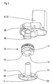
- Fig. 5 shows an exploded view of parts of the drive, with the third Drive housing part 22, part of the reduction gear 15 in the form of a Worm wheel and a mirror base 3, which is fixed to the body of a motor vehicle connected is.
- the reduction gear 15 is a two-stage worm gear that is self-locking.
- the worm wheel shown has locking means 13 in the form of Notches on the, in the assembled state between a driving and a Parking position with locking means 13 are engaged on the mirror base 3 in the form of locking cams.
- the locking means are provided on the sides with bevels, which act on the action of an external force Allow the locking means to snap out on the mirror.
- the guideway limiters 26 With bevels, they enable disengagement in one the stop positions, the driving or parking position.
- This relative movement is from Microswitch 9, which is designed as a push button switch, recognizable because it is only in the locked position State of the locking means between mirror base 3 and the worm wheel of Reduction gear 15 is acted upon by the mirror base 3.
- FIG. 6 shows an exterior rear view mirror 1 with a mirror glass 5, a mirror head 4 with which the drive 6 is firmly connected, while under the force of a compression spring 12 the mirror base 3 is locked.
- the exterior rearview mirror is motorized and by one of Force acting on the outside of the mirror head 4 can be pivoted about the pivot axis 7.
- the locking means 13 remain in the locked state while they are Action of an external force on the mirror head 4 due to the self-locking Disengage the reduction gear 15.
- the mirror head 4 shifts against the mirror base 3 against the force of the compression spring in the direction of Swivel axis and slides over the slopes of the locking means 13 and Travel limiter 26.
- the mirror base 3 is firmly connected to the motor vehicle 2.
- Fig. 7 shows the possible positions of the exterior rearview mirror.
- the motor can Move mirror head 4 between driving position F and parking position P. By a external force, the mirror head 4 can also have a position K in the direction of travel or a Reach intermediate position.
- the mirror glass 5 is usually by an additional drive adjustable about two perpendicular axes.
Landscapes
- Engineering & Computer Science (AREA)
- Multimedia (AREA)
- Mechanical Engineering (AREA)
- Rear-View Mirror Devices That Are Mounted On The Exterior Of The Vehicle (AREA)
Applications Claiming Priority (2)
| Application Number | Priority Date | Filing Date | Title |
|---|---|---|---|
| DE10006913 | 2000-02-16 | ||
| DE10006913A DE10006913B4 (de) | 2000-02-16 | 2000-02-16 | Außenrückblickspiegel für ein Kraftfahrzeug |
Publications (3)
| Publication Number | Publication Date |
|---|---|
| EP1125794A2 true EP1125794A2 (fr) | 2001-08-22 |
| EP1125794A3 EP1125794A3 (fr) | 2001-09-12 |
| EP1125794B1 EP1125794B1 (fr) | 2003-07-30 |
Family
ID=7631106
Family Applications (1)
| Application Number | Title | Priority Date | Filing Date |
|---|---|---|---|
| EP00120277A Expired - Lifetime EP1125794B1 (fr) | 2000-02-16 | 2000-09-28 | Rétroviseur pour véhicule |
Country Status (6)
| Country | Link |
|---|---|
| US (1) | US6543902B2 (fr) |
| EP (1) | EP1125794B1 (fr) |
| AT (1) | ATE246108T1 (fr) |
| DE (1) | DE10006913B4 (fr) |
| ES (1) | ES2204423T3 (fr) |
| WO (1) | WO2004074043A1 (fr) |
Cited By (1)
| Publication number | Priority date | Publication date | Assignee | Title |
|---|---|---|---|---|
| DE102010015785A1 (de) * | 2010-04-20 | 2011-10-20 | Autoliv Development Ab | Gurtaufroller mit einer mit einem Elektromotor antreibbaren Gurtwelle |
Families Citing this family (14)
| Publication number | Priority date | Publication date | Assignee | Title |
|---|---|---|---|---|
| WO2005068257A1 (fr) * | 2004-01-13 | 2005-07-28 | Truck-Lite Co., Inc. | Ensemble embrayage pour retroviseur liberable |
| ATE476320T1 (de) * | 2004-02-18 | 2010-08-15 | Smr Patents Sarl | Verschleissfeste halterung für klappspiegel |
| DE102006037660A1 (de) * | 2005-11-04 | 2007-07-19 | Continental Teves Ag & Co. Ohg | Hydraulische Fahrzeugbremse mit integrierter elektromotorisch betätigbarer Feststellbremse |
| NL1031808C2 (nl) * | 2006-05-12 | 2007-11-15 | Eaton Automotive Bv | Scharnierconstructie. |
| US20080253008A1 (en) * | 2007-04-10 | 2008-10-16 | Milo Tseng | Foldable Exterior Rearview Mirror For Motor Vehicle |
| AU2008203505B2 (en) * | 2008-08-05 | 2011-06-09 | Smr Patents S.A.R.L. | Vehicle mirror power fold mechanism |
| JP5173668B2 (ja) * | 2008-08-18 | 2013-04-03 | 株式会社ミツバ | 減速機構付モータ |
| NL2003061C2 (nl) * | 2009-06-22 | 2010-12-23 | Mci Mirror Controls Int Nl Bv | Spiegelverstelinrichting. |
| EP2439106B1 (fr) * | 2010-10-08 | 2012-12-05 | SMR Patents S.à.r.l. | Mécanisme escamotable à alimentation |
| JP6494371B2 (ja) * | 2015-03-31 | 2019-04-03 | 株式会社村上開明堂 | 車両用電動格納式視認装置 |
| DE102016102508B4 (de) * | 2016-02-12 | 2020-03-19 | Ficosa International Gmbh | Schwenkeinrichtung |
| DE102017200771A1 (de) | 2017-01-18 | 2018-07-19 | Mahle International Gmbh | Abgasturbolader mit Stelleinrichtung |
| DE102017006469B3 (de) | 2017-07-08 | 2018-11-22 | Audi Ag | Bedienvorrichtung zum Verstellen eines Kraftfahrzeugbauteils und Kraftfahrzeug |
| TR202013442A2 (tr) * | 2020-08-26 | 2020-12-21 | Feka Otomotiv Mamuelleri Sanayi Ve Ticaret Anonim Sirketi | Di̇ki̇z aynalari i̇çi̇n kullanilan bi̇r katlama mekani̇zmasi |
Family Cites Families (7)
| Publication number | Priority date | Publication date | Assignee | Title |
|---|---|---|---|---|
| NL8902300A (nl) | 1989-09-14 | 1991-04-02 | Iku Holding Montfoort Bv | Omklapmechanisme voor een spiegelhuis van een achteruitkijkspiegel voor een voertuig. |
| KR100198321B1 (ko) * | 1995-09-22 | 1999-06-15 | 모치마루 마모루 | 차량용 후시경의 위치결정장치 |
| NL1003144C2 (nl) * | 1996-05-15 | 1997-11-18 | Iku Holding Montfoort Bv | Elektrisch bedienbare scharnieractuator, en buitenspiegel met elektrisch bedienbaar scharniermechanisme. |
| DE69822701T2 (de) * | 1997-05-29 | 2005-01-13 | Schefenacker Vision Systems Australia Pty Ltd, Lonsdale | Betätigungsmechanismus für einen Rückblickspiegel |
| DE19833514B4 (de) | 1997-07-30 | 2005-04-28 | Buhler Motor Gmbh | Antrieb zum Abklappen eines Kraftfahrzeugrückblickspiegels |
| DE19813039B4 (de) * | 1998-03-25 | 2004-02-19 | Bühler Motor GmbH | Gehäuse, insbesondere eines Abklappantriebes für einen Kfz-Außenspiegel |
| DE10009670B4 (de) * | 2000-02-29 | 2005-08-04 | Bühler Motor GmbH | Außenrückblickspiegel für ein Kraftfahrzeug |
-
2000
- 2000-02-16 DE DE10006913A patent/DE10006913B4/de not_active Expired - Fee Related
- 2000-09-28 ES ES00120277T patent/ES2204423T3/es not_active Expired - Lifetime
- 2000-09-28 AT AT00120277T patent/ATE246108T1/de active
- 2000-09-28 EP EP00120277A patent/EP1125794B1/fr not_active Expired - Lifetime
-
2001
- 2001-02-15 US US09/926,338 patent/US6543902B2/en not_active Expired - Lifetime
- 2001-02-15 WO PCT/DE2001/000610 patent/WO2004074043A1/fr not_active Ceased
Non-Patent Citations (1)
| Title |
|---|
| None |
Cited By (2)
| Publication number | Priority date | Publication date | Assignee | Title |
|---|---|---|---|---|
| DE102010015785A1 (de) * | 2010-04-20 | 2011-10-20 | Autoliv Development Ab | Gurtaufroller mit einer mit einem Elektromotor antreibbaren Gurtwelle |
| DE102010015785B4 (de) | 2010-04-20 | 2023-07-13 | Autoliv Development Ab | Gurtaufroller mit einer mit einem Elektromotor antreibbaren Gurtwelle |
Also Published As
| Publication number | Publication date |
|---|---|
| EP1125794A3 (fr) | 2001-09-12 |
| EP1125794B1 (fr) | 2003-07-30 |
| DE10006913B4 (de) | 2005-12-22 |
| US20020141084A1 (en) | 2002-10-03 |
| US6543902B2 (en) | 2003-04-08 |
| ES2204423T3 (es) | 2004-05-01 |
| WO2004074043A1 (fr) | 2004-09-02 |
| ATE246108T1 (de) | 2003-08-15 |
| DE10006913A1 (de) | 2001-08-30 |
Similar Documents
| Publication | Publication Date | Title |
|---|---|---|
| EP1125794B1 (fr) | Rétroviseur pour véhicule | |
| DE68915925T2 (de) | Verriegelungsmechanismus für stecker- und sockelartigen elektrischen Verbinder. | |
| EP3867480B1 (fr) | Barrière de passage et procédé de production d'une barrière de passage | |
| DE102010008880B3 (de) | Antriebseinheit für einen Fahrzeugsitz | |
| DE102013101492B4 (de) | Verriegelungseinrichtung für eine Steckverbindung | |
| DE69223481T2 (de) | Elektrischer verbinder zur stromversorgung | |
| DE10033088B4 (de) | Aufschnappen des Spiegelantriebes | |
| DE102010061934B4 (de) | Ladeeinrichtung für ein Elektrofahrzeug | |
| DE19813039A1 (de) | Gehäuse, insbesondere eines Abklappantriebes für einen Kfz-Außenspiegel | |
| EP3408898B1 (fr) | Système de connexion électrique | |
| DE102021207229A1 (de) | Verbindungsvorrichtung zum Verbinden eines ersten elektrischen Kontakts mit einem zweiten elektrischen Kontakt für einen Elektromotor und Elektromotor | |
| EP1093969A2 (fr) | Asservissement, en particulier pour la commande de rétroviseurs de véhicules | |
| EP4078785B1 (fr) | Entraînement linéaire comprenant un boîtier de dispositif de commande | |
| EP1986281B1 (fr) | Procédé de fabrication d'une liaison électrique conductrice | |
| DE3926603A1 (de) | Vorrichtung mit haltewunschtaste | |
| EP0405196B1 (fr) | Commutateur avec plusieurs positions de commutation | |
| DE20313455U1 (de) | Umpolvorrichtung für elektromotorische Verstellantriebe | |
| EP1125795A2 (fr) | Dispositif d'entrainement pour un rétroviseur extérieur de véhicule | |
| EP4128445B1 (fr) | Système de connecteur enfichable | |
| DE19618589C1 (de) | Stößelschalter, insbesondere Bremslichtschalter, mit einer Schalterjustierung | |
| EP2095491A1 (fr) | Dispositif de connexion pour un mécanisme de commande auxiliaire d'un véhicule | |
| EP0297218A2 (fr) | Raccord enfichable | |
| DE102005005705A1 (de) | Kontaktierungsmittel für flexible elektrische Flachbandkabel | |
| DE273948C (fr) | ||
| DE10152813A1 (de) | Antriebsanordnung zum gesteuerten mehrachsigen Verstellen, insbesondere eines Kraftfahrzeug-Rückblickspiegels |
Legal Events
| Date | Code | Title | Description |
|---|---|---|---|
| PUAI | Public reference made under article 153(3) epc to a published international application that has entered the european phase |
Free format text: ORIGINAL CODE: 0009012 |
|
| PUAL | Search report despatched |
Free format text: ORIGINAL CODE: 0009013 |
|
| AK | Designated contracting states |
Kind code of ref document: A2 Designated state(s): AT BE CH CY DE DK ES FI FR GB GR IE IT LI LU MC NL PT SE Kind code of ref document: A2 Designated state(s): AT ES FR GB IT |
|
| AX | Request for extension of the european patent |
Free format text: AL;LT;LV;MK;RO;SI |
|
| AK | Designated contracting states |
Kind code of ref document: A3 Designated state(s): AT BE CH CY DE DK ES FI FR GB GR IE IT LI LU MC NL PT SE |
|
| AX | Request for extension of the european patent |
Free format text: AL;LT;LV;MK;RO;SI |
|
| 17P | Request for examination filed |
Effective date: 20010810 |
|
| AKX | Designation fees paid |
Free format text: AT ES FR GB IT |
|
| REG | Reference to a national code |
Ref country code: DE Ref legal event code: 8566 |
|
| GRAH | Despatch of communication of intention to grant a patent |
Free format text: ORIGINAL CODE: EPIDOS IGRA |
|
| GRAH | Despatch of communication of intention to grant a patent |
Free format text: ORIGINAL CODE: EPIDOS IGRA |
|
| GRAA | (expected) grant |
Free format text: ORIGINAL CODE: 0009210 |
|
| AK | Designated contracting states |
Designated state(s): AT ES FR GB IT |
|
| PG25 | Lapsed in a contracting state [announced via postgrant information from national office to epo] |
Ref country code: IT Free format text: LAPSE BECAUSE OF FAILURE TO SUBMIT A TRANSLATION OF THE DESCRIPTION OR TO PAY THE FEE WITHIN THE PRESCRIBED TIME-LIMIT;WARNING: LAPSES OF ITALIAN PATENTS WITH EFFECTIVE DATE BEFORE 2007 MAY HAVE OCCURRED AT ANY TIME BEFORE 2007. THE CORRECT EFFECTIVE DATE MAY BE DIFFERENT FROM THE ONE RECORDED. Effective date: 20030730 Ref country code: GB Free format text: LAPSE BECAUSE OF FAILURE TO SUBMIT A TRANSLATION OF THE DESCRIPTION OR TO PAY THE FEE WITHIN THE PRESCRIBED TIME-LIMIT Effective date: 20030730 Ref country code: FR Free format text: LAPSE BECAUSE OF FAILURE TO SUBMIT A TRANSLATION OF THE DESCRIPTION OR TO PAY THE FEE WITHIN THE PRESCRIBED TIME-LIMIT Effective date: 20030730 |
|
| REG | Reference to a national code |
Ref country code: GB Ref legal event code: FG4D Free format text: NOT ENGLISH |
|
| GBV | Gb: ep patent (uk) treated as always having been void in accordance with gb section 77(7)/1977 [no translation filed] |
Effective date: 20030730 |
|
| REG | Reference to a national code |
Ref country code: ES Ref legal event code: FG2A Ref document number: 2204423 Country of ref document: ES Kind code of ref document: T3 |
|
| PLBE | No opposition filed within time limit |
Free format text: ORIGINAL CODE: 0009261 |
|
| STAA | Information on the status of an ep patent application or granted ep patent |
Free format text: STATUS: NO OPPOSITION FILED WITHIN TIME LIMIT |
|
| 26N | No opposition filed |
Effective date: 20040504 |
|
| EN | Fr: translation not filed | ||
| PGFP | Annual fee paid to national office [announced via postgrant information from national office to epo] |
Ref country code: AT Payment date: 20130926 Year of fee payment: 14 |
|
| PGFP | Annual fee paid to national office [announced via postgrant information from national office to epo] |
Ref country code: ES Payment date: 20140730 Year of fee payment: 15 |
|
| REG | Reference to a national code |
Ref country code: AT Ref legal event code: MM01 Ref document number: 246108 Country of ref document: AT Kind code of ref document: T Effective date: 20140928 |
|
| PG25 | Lapsed in a contracting state [announced via postgrant information from national office to epo] |
Ref country code: AT Free format text: LAPSE BECAUSE OF NON-PAYMENT OF DUE FEES Effective date: 20140928 |
|
| REG | Reference to a national code |
Ref country code: ES Ref legal event code: FD2A Effective date: 20161028 |
|
| PG25 | Lapsed in a contracting state [announced via postgrant information from national office to epo] |
Ref country code: ES Free format text: LAPSE BECAUSE OF NON-PAYMENT OF DUE FEES Effective date: 20150929 |