EP1126192A2 - Automatisches Getriebe - Google Patents
Automatisches Getriebe Download PDFInfo
- Publication number
- EP1126192A2 EP1126192A2 EP01103330A EP01103330A EP1126192A2 EP 1126192 A2 EP1126192 A2 EP 1126192A2 EP 01103330 A EP01103330 A EP 01103330A EP 01103330 A EP01103330 A EP 01103330A EP 1126192 A2 EP1126192 A2 EP 1126192A2
- Authority
- EP
- European Patent Office
- Prior art keywords
- gear
- shaft
- automatic transmission
- clutch
- shift
- Prior art date
- Legal status (The legal status is an assumption and is not a legal conclusion. Google has not performed a legal analysis and makes no representation as to the accuracy of the status listed.)
- Withdrawn
Links
- 230000005540 biological transmission Effects 0.000 title claims abstract description 147
- 230000007246 mechanism Effects 0.000 claims abstract description 52
- 230000003247 decreasing effect Effects 0.000 claims description 9
- 238000011144 upstream manufacturing Methods 0.000 claims 1
- 238000010586 diagram Methods 0.000 description 18
- 230000002441 reversible effect Effects 0.000 description 13
- 230000007935 neutral effect Effects 0.000 description 10
- 230000008859 change Effects 0.000 description 6
- 230000004048 modification Effects 0.000 description 5
- 238000012986 modification Methods 0.000 description 5
- 230000001360 synchronised effect Effects 0.000 description 5
- 230000001276 controlling effect Effects 0.000 description 4
- 230000000694 effects Effects 0.000 description 4
- 230000035939 shock Effects 0.000 description 4
- 230000000670 limiting effect Effects 0.000 description 3
- 238000004519 manufacturing process Methods 0.000 description 3
- 230000000717 retained effect Effects 0.000 description 3
- 238000010276 construction Methods 0.000 description 2
- 230000008878 coupling Effects 0.000 description 2
- 238000010168 coupling process Methods 0.000 description 2
- 238000005859 coupling reaction Methods 0.000 description 2
- 230000000994 depressogenic effect Effects 0.000 description 2
- 239000012530 fluid Substances 0.000 description 2
- 239000000446 fuel Substances 0.000 description 2
- 238000000034 method Methods 0.000 description 2
- 230000008569 process Effects 0.000 description 2
- 230000009467 reduction Effects 0.000 description 2
- 230000001105 regulatory effect Effects 0.000 description 2
- 238000005299 abrasion Methods 0.000 description 1
- 230000004308 accommodation Effects 0.000 description 1
- 230000002829 reductive effect Effects 0.000 description 1
- 238000004513 sizing Methods 0.000 description 1
Images








Classifications
-
- F—MECHANICAL ENGINEERING; LIGHTING; HEATING; WEAPONS; BLASTING
- F16—ENGINEERING ELEMENTS AND UNITS; GENERAL MEASURES FOR PRODUCING AND MAINTAINING EFFECTIVE FUNCTIONING OF MACHINES OR INSTALLATIONS; THERMAL INSULATION IN GENERAL
- F16H—GEARING
- F16H3/00—Toothed gearings for conveying rotary motion with variable gear ratio or for reversing rotary motion
- F16H3/02—Toothed gearings for conveying rotary motion with variable gear ratio or for reversing rotary motion without gears having orbital motion
- F16H3/08—Toothed gearings for conveying rotary motion with variable gear ratio or for reversing rotary motion without gears having orbital motion exclusively or essentially with continuously meshing gears, that can be disengaged from their shafts
- F16H3/12—Toothed gearings for conveying rotary motion with variable gear ratio or for reversing rotary motion without gears having orbital motion exclusively or essentially with continuously meshing gears, that can be disengaged from their shafts with means for synchronisation not incorporated in the clutches
-
- F—MECHANICAL ENGINEERING; LIGHTING; HEATING; WEAPONS; BLASTING
- F16—ENGINEERING ELEMENTS AND UNITS; GENERAL MEASURES FOR PRODUCING AND MAINTAINING EFFECTIVE FUNCTIONING OF MACHINES OR INSTALLATIONS; THERMAL INSULATION IN GENERAL
- F16H—GEARING
- F16H61/00—Control functions within control units of change-speed- or reversing-gearings for conveying rotary motion ; Control of exclusively fluid gearing, friction gearing, gearings with endless flexible members or other particular types of gearing
- F16H61/04—Smoothing ratio shift
-
- F—MECHANICAL ENGINEERING; LIGHTING; HEATING; WEAPONS; BLASTING
- F16—ENGINEERING ELEMENTS AND UNITS; GENERAL MEASURES FOR PRODUCING AND MAINTAINING EFFECTIVE FUNCTIONING OF MACHINES OR INSTALLATIONS; THERMAL INSULATION IN GENERAL
- F16H—GEARING
- F16H61/00—Control functions within control units of change-speed- or reversing-gearings for conveying rotary motion ; Control of exclusively fluid gearing, friction gearing, gearings with endless flexible members or other particular types of gearing
- F16H61/04—Smoothing ratio shift
- F16H2061/0425—Bridging torque interruption
-
- F—MECHANICAL ENGINEERING; LIGHTING; HEATING; WEAPONS; BLASTING
- F16—ENGINEERING ELEMENTS AND UNITS; GENERAL MEASURES FOR PRODUCING AND MAINTAINING EFFECTIVE FUNCTIONING OF MACHINES OR INSTALLATIONS; THERMAL INSULATION IN GENERAL
- F16H—GEARING
- F16H61/00—Control functions within control units of change-speed- or reversing-gearings for conveying rotary motion ; Control of exclusively fluid gearing, friction gearing, gearings with endless flexible members or other particular types of gearing
- F16H61/04—Smoothing ratio shift
- F16H2061/0425—Bridging torque interruption
- F16H2061/0429—Bridging torque interruption by torque supply with a clutch in parallel torque path
-
- Y—GENERAL TAGGING OF NEW TECHNOLOGICAL DEVELOPMENTS; GENERAL TAGGING OF CROSS-SECTIONAL TECHNOLOGIES SPANNING OVER SEVERAL SECTIONS OF THE IPC; TECHNICAL SUBJECTS COVERED BY FORMER USPC CROSS-REFERENCE ART COLLECTIONS [XRACs] AND DIGESTS
- Y10—TECHNICAL SUBJECTS COVERED BY FORMER USPC
- Y10T—TECHNICAL SUBJECTS COVERED BY FORMER US CLASSIFICATION
- Y10T74/00—Machine element or mechanism
- Y10T74/19—Gearing
- Y10T74/19219—Interchangeably locked
- Y10T74/19233—Plurality of counter shafts
-
- Y—GENERAL TAGGING OF NEW TECHNOLOGICAL DEVELOPMENTS; GENERAL TAGGING OF CROSS-SECTIONAL TECHNOLOGIES SPANNING OVER SEVERAL SECTIONS OF THE IPC; TECHNICAL SUBJECTS COVERED BY FORMER USPC CROSS-REFERENCE ART COLLECTIONS [XRACs] AND DIGESTS
- Y10—TECHNICAL SUBJECTS COVERED BY FORMER USPC
- Y10T—TECHNICAL SUBJECTS COVERED BY FORMER US CLASSIFICATION
- Y10T74/00—Machine element or mechanism
- Y10T74/19—Gearing
- Y10T74/19219—Interchangeably locked
- Y10T74/19242—Combined gear and clutch
-
- Y—GENERAL TAGGING OF NEW TECHNOLOGICAL DEVELOPMENTS; GENERAL TAGGING OF CROSS-SECTIONAL TECHNOLOGIES SPANNING OVER SEVERAL SECTIONS OF THE IPC; TECHNICAL SUBJECTS COVERED BY FORMER USPC CROSS-REFERENCE ART COLLECTIONS [XRACs] AND DIGESTS
- Y10—TECHNICAL SUBJECTS COVERED BY FORMER USPC
- Y10T—TECHNICAL SUBJECTS COVERED BY FORMER US CLASSIFICATION
- Y10T74/00—Machine element or mechanism
- Y10T74/19—Gearing
- Y10T74/19219—Interchangeably locked
- Y10T74/19251—Control mechanism
-
- Y—GENERAL TAGGING OF NEW TECHNOLOGICAL DEVELOPMENTS; GENERAL TAGGING OF CROSS-SECTIONAL TECHNOLOGIES SPANNING OVER SEVERAL SECTIONS OF THE IPC; TECHNICAL SUBJECTS COVERED BY FORMER USPC CROSS-REFERENCE ART COLLECTIONS [XRACs] AND DIGESTS
- Y10—TECHNICAL SUBJECTS COVERED BY FORMER USPC
- Y10T—TECHNICAL SUBJECTS COVERED BY FORMER US CLASSIFICATION
- Y10T74/00—Machine element or mechanism
- Y10T74/19—Gearing
- Y10T74/19219—Interchangeably locked
- Y10T74/19377—Slidable keys or clutches
- Y10T74/19386—Multiple clutch shafts
- Y10T74/194—Selective
Definitions
- the present invention relates to an automatic transmission and more particularly to an automatic transmission whose gear mechanism is of a conventional manual transmission.
- the automatic transmission of this type has a plurality of gear trains arranged in an axial direction of the transmission and changeover mechanisms for changing gear trains. The shift change is performed by automatically controlling these changeover mechanisms by means of hydraulic pressure.
- This type automatic transmission has an excellent transmission efficiency of power, compared to a conventional automatic transmission primarily constituted by planetary gears, friction engagement elements (clutches, brakes) and the like. Further, since this type automatic transmission is constituted by a small number of components, it is easier to design a light weight and low cost transmission than a conventional type automatic transmission.
- Japanese Patent Application Laid-open No. Toku-Kai-Sho 63-2735 discloses a structure of an automatic transmission in which a sub clutch for preventing a "torque drop" at shifting gears is equipped in addition to a main clutch disposed between a crank shaft of an engine and an input shaft of the transmission. This sub clutch is disposed at an end of the input shaft of the transmission.
- the sub clutch is partially engaged by hydraulic pressure while the main clutch is held in full engagement, thereby an output torque during shifting gears is prevented from dropping abruptly and a shift shock at up-shift is alleviated.
- automatic transmissions having similar constructions are disclosed in Japanese Patent Application Laid open No. Toku-Kai-Sho 61-45163 and Japanese Patent No. 2703169.
- Japanese Patent Application No. Toku-Kai-Sho 58-149443 discloses a construction in which a sub clutch is disposed on an axis of a counter shaft provided in parallel with an input shaft and an output shaft of the transmission. Specifically, a drive gear of a second speed gear train and a drive gear of a fourth speed gear train are rotatably mounted on the counter shaft and a changeover mechanism is interposed between these drive gears. Further, driven gears of these gear trains are secured to the output shaft provided in parallel with the counter shaft. Further, the sub clutch is disposed at the end of the counter shaft corresponding to a mounting shaft of the shift gears (drive gears). The sub clutch is engaged or disengaged by hydraulic pressure on shifting gears.
- the sub clutch is disposed on the mounting shaft of the shift gears. Normally, a plurality of drive gears and a shift mechanism including changeover mechanisms and the like are disposed almost on allover the mounting shaft in an axial direction. Accordingly, in case where a sub clutch is mounted on the mounting shaft, in order to secure a space for accommodating the sub clutch on the mounting shaft, it is necessary to enlarge a longitudinal or axial size of the mounting shaft. Hence, an axial size of the transmission becomes larger than that of a prior type transmission. As a result, it becomes difficult to maintain the exchangeability with a prior type of a transmission (for example, manual transmission).
- an automatic transmission having an input shaft, an output shaft, a main clutch for transmitting a power of an engine to the input shaft, shift gear trains for producing a specified gear ratio and a plurality of changeover mechanisms for automatically changing over the shift gear trains at shifting gears, comprises a plurality of mounting shafts for mounting respective shift gears of the shift gear trains, an intermediate shaft disposed on an axis other than axes of the mounting shafts and a sub clutch mounting on the intermediate shaft for variably controlling a torque transmitted from the input shaft to the output shaft when shifting gears.
- Fig. 1 is a skeleton diagram showing an automatic transmission having five forward speed ratios and Fig. 2 is a sectional view of the transmission.
- This automatic transmission is a transaxle type transmission transversely mounted on a vehicle.
- an input shaft 1, an output shaft 2, an idler shaft 3 and an intermediate shaft 4 are disposed in parallel with each other.
- the intermediate shaft 4 is disposed at an axis different from an axis of the input shaft 1 and also from an axis of the output shaft 2.
- Torque inputted from an engine (not shown) is transmitted from the input shaft 1 to the output shaft 2 through a specific gear train.
- Amain clutch 5 (in this embodiment, single disc clutch) is engaged or disengaged by a hydraulic control to transmit a power of a crankshaft (not shown) of the engine to the input shaft 1 of the automatic transmission or to shut off the power.
- a flywheel 5a is directly connected with the crankshaft and a clutch disk 5c is provided between the flywheel 5a and a pressure plate 5b.
- the clutch disc 5c is spline-fitted over the input shaft 1 through a clutch hub provided on an inner periphery surface thereof .
- a release bearing 5d is slidably mounted on the input shaft 1.
- gear trains by which respective speed ratios are established from the 1st gear ratio to the 5th gear ratio between the input shaft 1 and the output shaft 2.
- a 1st speed gear train 6 and 7 With respect to forward gear trains, a 1st speed gear train 6 and 7, a 2nd speed gear train 8 and 9, a 3rd speed gear train 10 and 11, a 4th speed gear train 12 and 13, and a 5th speed gear train 14 and 15 are arranged from left to right in this order.
- a 1st speed drive gear 6 is fixedly mounted on the input shaft 1.
- a 1st speed driven gear 7 meshing with the drive gear 6 is rotatably mounted on the output shaft 2.
- a 2nd speed drive gear 8 is fixedly mounted on the input shaft 1 and a 2nd speed driven gear 9 meshing with the drive gear 8 is rotatably mounted on the output shaft 2.
- a 3rd speed drive gear 10 is rotatably mounted on the input shaft 1 and a 3rd speed driven gear 11 meshing with the drive gear 10 is fixedly mounted on the output shaft 2.
- a 4th speed drive gear 12 is rotatably mounted on the input shaft 1 and a 4th speed driven gear 13 meshing with the drive gear 12 is fixedly mounted on the output shaft 2.
- a 5th speed drive gear 14 is rotatably mounted on the input shaft 1 and a 5th speed driven gear 15 meshing with the drive gear 14 is fixedly mounted on the output shaft 2.
- the speed ratio of respective shift stages is determined by a gear ratio of the corresponding gear train.
- the changeover between the respective forward speed gear trains is performed by three synchromesh mechanism 16, 17 and 18.
- a first synchromesh mechanism 16 is provided on the output shaft 2 between the 1st speed driven gear 7 and the 2nd speed driven gear 9.
- a second synchromesh mechanism 17 is provided on the input shaft 1 between the 3rd speed drive gear 10 and the 4th speed drive gear 12.
- a third synchromesh mechanism 18 is provided on the input shaft 1 in the vicinity of the 5th speed drive gear.
- the structure of these synchromesh mechanisms 16, 17 and 18 is of a well-known type. As shown in Fig. 2, the shift of synchrosleeves 16a, 17a and 18a in an axial direction is automatically controlled by hydraulic pressure.
- this automatic control is accompanied by a synchronized control of a sub clutch 27 which will be described hereinafter.
- a sub clutch 27 Describing only the shift motion of the synchromesh mechanisms 16, 17 and 18, for example, in case where the gear ratio is set to the 1st speed ratio, the synchrosleeve 16a is shifted leftward by hydraulic pressure while the synchrosleeves 17a and 18a are held in a neutral position, respectively. As the shift amount of the synchrosleeve 16a increases, the rotation of the synchrosleeve 16a is synchronized with that of the 1st speed driven gear 7.
- an outer spline integrally formed with the 1st speed driven gear 7 is fitted to an inner spline of the sleeve 16a.
- the synchrosleeve 16a is constantly spline-fitted over a synchrohub 16b rotating integrally with the output shaft 2. Accordingly, the driving force of the input shaft 1 is transmitted to the output shaft 2 through the 1st speed gear train 6 and 7, the synchrosleeve 16a and the synchrohub 16b.
- the synchrosleeve 16a is shifted rightward by hydraulic pressure while the synchrosleeves 17a and 18a are retained in a neutral position, respectively.
- the synchrosleeve 17a is shifted with other synchrosleeves set in a neutral position and in order to set the gear ratio to a 5th speed ratio, the synchrosleeve 18a is shifted while other synchrosleeves is set in a neutral position.
- the driving force of the input shaft 1 is transmitted to the output shaft 2 through the gear train selected by either of the synchromesh mechanisms 16, 17 and 18. Further, the rotation speed of the output shaft 2 is reduced by a final reduction gear train 19 and then the driving force is transmitted to a differential 20. Thus, the driving force is transmitted to driving wheels 21 and the driving wheels rotate in the forward direction.
- first all synchromesh mechanisms 16, 17 and 18 are set to a neutral condition.
- a reverse driven gear 28 integrally mounted on the outer periphery of the synchrosleeve 16a and a reverse drive gear 25 fixedly mounted on the input shaft 1 are arranged on the same plane perpendicular to the input shaft 1.
- an idler gear 26 rotatably mounted on an idler shaft 3 slides in an axial direction on the idler shaft 3, the idler gear 26 meshes with both of the reverse drive gear 25 and the reverse driven gear 28.
- the driving force of the input shaft 1 is transmitted to the output shaft 2 through the reverse drive gear 25, the idler gear 26 and the reverese driven gear 28. Since the driving force is transmitted to the output shaft 2 via the idler gear 26, the output shaft 2 rotates reversely.
- the intermediate shaft 4 arranged below the input shaft 1 is provided with a sub clutch 27 composed of a hydraulically controlled multiple disc clutch.
- the sub clutch 27 has a pair of rotation members comprising a clutch drum 27a and a clutch hub 27b.
- a first intermediate gear 22 is fixedly mounted at an end of the input shaft 1 (on an opposite side of the main clutch 5) and meshes with a second intermediate gear 23 rotatably mounted on the intermediate shaft 4. This second intermediate gear 23 is integrally connected with the clutch drum 27a.
- the clutch hub 27b of the sub clutch 27 is integrally connected with a third intermediate gear 24 fixedly mounted on the intermediate shaft 4. Further, the third intermediate gear 24 meshes with the 5th speed driven gear 15 integrally mounted on the output shaft 2 through the 5th speed drive gear 14 rotatably mounted on the input shaft 1.
- the gear ratio of the gear train 22, 23 or the gear train 14, 24 is established on a speed increase side or a speed reduction side.
- the gear is changed from 1st to 2nd or from 2nd to 3rd, that is, when the gear change is performed on a low speed side, the shift shock due to a torque drop is relatively large.
- the gear is changed from 4th to 5th, that is, when the gear change is performed on a high speed side, the shift shock is not so large as a driver feels uncomfortable. Accordingly, an overall gear ratio including the input gear train 22 and 23 and the output gear train 24, 14 and 15 is established at a value corresponding to the 3rd to 4th gear position.
- the number of teeth is 20 for the first intermediate gear 22 and is 30 for the second intermediate gear 23. Accordingly, the gear ratio of the input gear train 22 and 23 is established at 1.5. Further, the number of teeth is 15 for the 5th speed driven gear 15 and is 24 for the third intermediate gear 24. Hence, the gear ratio on the output side is established at 0.75.
- the total gear ratio including the input gear train 22 and 23 and the output gear train 24, 14 and 15 is established at 1.125. This value corresponds to a speed ratio between the 3rd gear ratio (for example 1.3) and the 4th gear ratio (for example 1.0).
- a shift control section 31 of the system receives miscellaneous signals, such as engine speed Ne, accelerator pedal opening angle ⁇ (or throttle valve opening angle), vehicle speed V, revolution speed of the input shaft 1 Ni, selected gear position PG, position of a selector lever SL and the like. Then, based on these signals the shift control section 31 determines a gear position corresponding to the current traveling condition and outputs appropriate control signals to a hydraulic circuit 32.
- the hydraulic circuit 32 is constituted by an oil pump driven by an engine or an electric motor, an electromagnetic valve and the like and supplies a regulated hydraulic pressure to the main clutch 5, the sub clutch 27 and hydraulic actuators 33 respectively, according to the control signals from the shift control section 31.
- the hydraulic actuators 33 include miscellaneous actuators for sliding the synchrosleeves 16a, 17a and 18a and the idler gear 26.
- the main clutch 5, the sub clutch 27 and the synchromesh mechanisms 16, 17 and 18 are controlled in the following manner. First, when the selector position SL is established at a forward traveling range by operating a selector lever, the synchrosleeve 16a is shifted toward the first speed drive gear 6 to select the first gear position. Further, when the accelerator pedal is depressed, the main clutch 5 is engaged by hydraulic pressure fed from the hydraulic circuit 32 and the vehicle travels . Further, with an increase of the vehicle speed, the gear is up-shifted according to the shift schedule programmed in the shift control section 31.
- the sub clutch 27 starts engagement while the main clutch 5 is fully engaged and is held in a partially engaged state.
- two power delivery paths one is a path through the first speed gear train 6 and 7 and another is a path through the sub clutch 27, are formed. That is, as shown in Fig. 3, the power of the input shaft 1 is transmitted to the clutch drum 27a of the sub clutch 27 through the gear train 22, 23 which rotates integrally with the input shaft 1 (arrow mark a). Next, the power of the clutch drum 27a is transmitted to the clutch hub 27b according to the degree of engagement. Further, the power is transmitted to the output shaft 2 through the gear train 24, 14, 15 (arrow marks b, c). In this power delivery path, the fifth speed drive gear 14 acts as an idler gear.
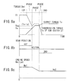
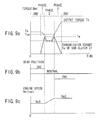
- Fig. 8 shows a transference of the transmission torque control of the sub clutch 27 when the gear is up-shifted from the 1st gear position to the 2nd gear position.
- the total gear ratio Ia of the input and output gear trains is established at 1.125 (corresponding to the speed ratio between 3rd gear position and the 4th gear position)
- a part of the torque of the input shaft 1 is delivered to the output shaft 2 through the sub clutch 27 according to the state of engagement of the sub clutch 27.
- the transmission torque Ta of the sub clutch 27 is equalized with the engine torque Te, in other words, when all engine torque Te is delivered through the sub clutch 27, the transmission torque T1 of the first speed gear train 6, 7 becomes substantially zero.
- the synchrosleeve 16a of the first synchromesh mechanism 16 is shifted to a neutral position (phase 1).
- the first synchromesh mechanism 16 comes into a neutral state.
- the transmission torque Ta of the sub clutch 27 goes up, the power delivered through the gear trains 22, 23, 24, 14, 15 is outputted to the output shaft 2.
- the sub clutch 27 can be accommodated in the transmission efficiently without increasing the axial or longitudinal size of the transmission.
- gear trains and shift mechanisms are mounted on almost allover the mounting shaft of shift gears in the axial direction
- the sub clutch 27 is mounted on the mounting shaft, it is necessary that the length of the mounting shaft is elongated by the accommodation space.
- the sub clutch 27 is mounted on the intermediate shaft 4 provided specially, separately from the input or output shaft. Accordingly, it is not necessary to elongate the length of the input and output shafts 1, 2.
- the transmission case has almost the same axial size as the manual transmission having identical numbers of gear positions, the exchangeability with other types of transmission can be secured when it is mounted on a vehicle.
- the layout of the automatic transmission it is not necessary to make a large modification of an original manual transmission on which the automatic transmission is based.
- the layout of components around the input and output shafts 1, 2 is identical to that of the manual transmission except for the first intermediate gear 22 newly added at the end of the input shaft 1.
- the input gear train 22, 23 is added but, with respect to the output gear train, the 5th speed gear train 14, 15 is employed. Accordingly, it is not necessary to add a new gear to the output shaft 2.
- the output gear train of the sub clutch 27 is constituted using the original gear train 14, 15, it is not necessary to make big modifications of the layout around the input and output shafts 1, 2. As a result, it is possible to share components or manufacturing facilities between automatic transmissions and manual transmissions.
- the automatic transmission according to this embodiment has a relatively small number of components compared to the ordinary automatic transmission, it is easy to reduce weight and manufacturing cost. Further, since the automatic transmission of this type has a high power transmission efficiency, it is possible to contribute to the realization of high fuel economy cars.
- Fig. 10 is a skeleton diagram showing a five forward speed automatic transmission according to a second embodiment.
- This is a transaxle type transmission longitudinally mounted on a vehicle.
- Reference numeral 41 denotes a front drive shaft for transmitting power to front wheels.
- the front drive shaft penetrates a hollow output shaft 2 in the axial direction and is rotatably mounted on the output shaft 2.
- reference numeral 42 denotes a rear drive shaft for transmitting power to rear wheels.
- the power transmitted to the output shaft 2 is distributed into the front drive shaft 41 and the rear drive shaft 42 through a planetary center differential 40.
- the power of the front drive shaft 41 is transmitted to left and right front wheels through a front differential 43.
- the power of the rear drive shaft 42 is transmitted to left and right rear wheels through a rear differential (not shown).
- a differential limiting mechanism 44 constituted by a multiple disc clutch is interposed between the planetary center differential 40 and the rear drive shaft 42. This differential limiting mechanism 44 is provided for obtaining good maneuverability.
- the engagement condition of the multiple disc clutch in the mechanism 44 is controlled according to vehicle traveling conditions (for example, a degree of tire slip, a steering angle).
- the sub clutch can be accommodated efficiently without increasing the axial size of the transmission, while the exchangeability with other types of transmission is retained.
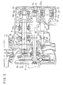
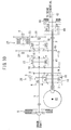
- Fig. 4 is a skeleton diagram showing a five forward speed automatic transmission according to a third embodiment and Fig. 5 is a sectional view of the transmission.
- This is a transaxle type transmission transversely mounted on a vehicle in the same manner as in the first embodiment.
- the third synchromesh mechanism 18 is mounted on the output shaft 2 and the 5th speed drive gear 14 is fixedly mounted on the input shaft 1. Further, the 5th speed driven gear meshing with this drive gear 14 is rotatably mounted on the output shaft 2.
- the synchrosleeve 18a is spline-fitted over the 5th speed driven gear , the power of the input shaft 1 is transmitted to the output shaft 2 through the gear train 14, 15, the synchrosleeve 18a and the synchro hub 18b.
- This automatic transmission has a second intermediate shaft 51 newly added in addition to the input shaft 1, the output shaft 2 and the intermediate shaft 4.
- a first intermediate gear 52 fixedly mounted on the intermediate shaft 4 (hereinafter referred to as a first intermediate shaft) meshes with the 5th speed drive gear 14 and at the same time is integrally connected with the clutch hub 27b of the sub clutch 27.
- a second intermediate gear 53 rotatably mounted on the first intermediate shaft 4 is integrally connected with the clutch drum 27a and meshes with a third intermediate gear 54 (idler gear) rotatably mounted on the second intermediate 51.
- the third intermediate gear 54 meshes with a fourth intermediate gear 55 fixedly mounted on the output shaft 2.
- the first intermediate shaft 4 on which the sub clutch 27 is mounted is provided on an axis different from the input and output shafts 1, 2.
- the gear ratio of the input gear train 14, 52 or the output gear train 53, 54 and 55 of the sub clutch 27 is established on a speed increasing side or on a speed decreasing side.
- the total gear ration of the input gear train 14, 52 and the output gear train 53, 54 and 55 is established at a value corresponding to the 3rd to 4th gear ratios.
- This embodiment has the same effect as in the first and second embodiments.
- the layout around the input and output shafts 1, 2 is the same as in the manual transmission except for a fourth intermediate gear 55 added at the end of the output shaft 2. That is, in order to constitute an output gear train of the sub clutch 27, the fourth intermediate gear 55 and the third intermediate gear 54 mounted on the second intermediate shaft 51 are added.
- the existing 5 th speed drive gear 14 is employed. Therefore, with respect to the input gear train, it is not necessary to add a new gear to the input shaft 1.
- the modification of the layout around the input and output shafts 1, 2 can be minimized.
- the gear of the 5th gear position is employed for the gear train of the sub clutch 27, however shift gears of other gear position may be used.
- Fig. 11 is a skeleton diagram showing a five forward speed automatic transmission according to a fourth embodiment of the present invention.
- This is an automatic transmission longitudinally mounted on a front engine rear drive (hereinafter referred to as "FR") vehicle.
- FR front engine rear drive
- the input shaft 1 is arranged coaxially with the output shaft 2.
- the intermediate shaft 4 is arranged on a different axis from the counter shaft 69 corresponding to one mounting shaft of transmission gears and also on a different axis from the output shaft 2 corresponding to the other mounting shaft of transmission gears.
- the power transmitted from an engine to the input shaft 1 is delivered to the counter shaft 69 through the 4th speed gear train 62, 63 and transmitted to the output shaft 2 through a specific gear train.
- the main clutch 5 of a single disc type serves as transmitting or shutting off the power of the crankshaft of the engine by a hydraulic control.
- shift gear trains each of which determines respective speed ratios from 1st to 5th between the input shaft 1, the output shaft 2 coaxially coupled with the input shaft 1 and the counter shaft 69.
- the 4th speed gear train 62, 63, the 3rd speed gear train 60, 61, the 2nd speed gear train 38, 39, the 1st speed gear train 36, 37 and the 5th speed gear train 64, 65 are disposed in the axial direction from left to right in this order.
- the 1 st speed drive gear 36 is fixedly mounted on the counter shaft 69. Further, the 1st speed driven gear 37 meshing with this drive gear 36 is rotatably mounted on the output shaft 2. Similarly, the 2nd speed drive gear 38 is fixedly mounted on the counter shaft 69 and the 2nd speed driven gear 39 meshing with the drive gear 38 is rotatably mounted on the output shaft 2. On the other hand, the 3rd speed drive gear 60 is fixedly mounted on the counter shaft 69 and the 3rd speed driven gear 61 meshing with the drive gear 60 is rotatably mounted on the output shaft 2. Further, a gear 62 is secured to the input shaft 1 and a synchromesh mechanism 17 directly engageable with this gear 62 is mounted on the output shaft 2.
- the 5th drive speed drive gear 64 is rotatably mounted on the counter shaft 69 and the 5th speed driven gear 45 meshing with this drive gear 64 is fixedly mounted on the output shaft 2.
- the speed ratio of respective gear positions is determined by the gear ratio of a corresponding shift gear train.
- the changeover of the respective forward shift gears is performed by operating three synchromesh mechanisms 16, 17 and 18 in the same way as described in the first embodiment.
- first all synchromesh mechanisms 16, 17 and 18 are set to a neutral condition.
- a reverse drive gear 70 fixedly mounted on the counter shaft 69 and a reveres driven gear 71 fixedly mounted on the are arranged on the same plane perpendicular to the counter shaft 69.
- an idler gear 72 rotatably mounted on an idler shaft 3 slides in an axial direction on the idler shaft 3, the idler gear 72 meshes with both of the reverse drive gear 70 and the reverse driven gear 71.
- the driving force of the counter shaft 69 is transmitted to the output shaft 2 through the reverse drive gear 70, the idler gear 72 and the reverese driven gear 71. Since the driving force is transmitted to the output shaft 2 via the idler gear 72, the output shaft 2 rotates reversely.
- the intermediate shaft 4 arranged below the counter shaft 69 is provided with a sub clutch 27 composed of a hydraulically controlled multiple disc clutch.
- the sub clutch 27 has a pair of rotation members comprising a clutch drum 27a and a clutch hub 27b.
- the sub clutch 27 is partially engaged, so a torque delivery path passing through a gear train 60, 73, the sub clutch 27,a gear train 74, 64 and 65, is established between the counter shaft 69 and the output shaft 2.
- a first intermediate gear 73 is rotatably mounted at an end of the intermediate shaft 4 and meshes with a 3rd speed drive gear 40 fixedly mounted on the counter shaft 69.
- This first intermediate gear 73 is integrally connected with the clutch drum 27a. Further, the clutch hub 27b of the sub clutch 27 is integrally connected with a second intermediate gear 74 fixedly mounted on the intermediate shaft 4. Further, the second intermediate gear 74 meshes with a fifth speed drive gear 64 rotatably mounted on the counter shaft 69. Accordingly, the power outputted from the sub clutch 27 (the power on the clutch hub side 27b) is transmitted to the output shaft 2 through the output gear train 74, 64 and 65.
- an overall gear ratio including the input gear train 60, 63 and the output gear train 74, 64 and 65 is established at a value corresponding to the 3rd to 4th gear position from the same view point as in the first embodiment.
- Fig. 12 is a skeleton diagram showing a five forward speed automatic transmission according to a fifth embodiment of the present invention.
- This transmission is a transaxle type transmission longitudinally mounted on a four wheel drive vehicle.
- Reference numeral 78 denotes a front drive shaft for transmitting power to front wheels.
- the front drive shaft 78 is rotatably fitted to a hollow counter shaft 69.
- reference numeral 79 denotes a rear drive shaft for transmitting power to rear wheels.
- the 4th speed gear train 62, 63, the 3rd speed gear train 60, 61, the 2nd speed gear train 38, 39, the 1st speed gear train 36, 37 and the 5th speed gear train 64, 65 are disposed in the axial direction from left to right in this order.
- the drive gears 36, 38, 60, 63 and 64 are fixedly mounted on the counter shaft 69 and the driven gears 37, 39, 61, 62 and 65 are rotatably mounted on the output shaft 2.
- the third synchromesh mechanism 18 is disposed on the output shaft 2 between the 5th speed driven gear 65 and the reverse driven gear 71.
- the power transmitted from the engine through the main clutch 5 of the input shaft 1 is delivered to the counter shaft 69 through the 4th gear train 62, 63.
- the power of the counter shaft 69 is transmitted to the output shaft 2 through a forward gear train selected by operating either of the synchromesh mechanisms 16, 17 and 18 and is distributed by a planetary center differential 80 into a front drive shaft 78 and a rear drive shaft 79.
- the power of the front drive shaft 78 is transmitted to the front wheels through a front differential 76 and the power of the rear drive shaft 29 is transmitted to the rear wheels through a rear differential (not shown).
- a differential limiting mechanism 30 constituted by a multiple disc clutch is interposed between a carrier of the center differential 80 and the rear drive shaft 79.
- the synchromesh mechanism 18 is changed over to a reverse driven gear 71 side with the synchmesh mechanisms 16, 17 retained in a neutral position.
- the power of the counter shaft 69 is transmitted to the output shaft 2 through the 1st speed drive gear 36, the idler gear 72 and the reverse driven gear 71.
- the rotational direction of the output shaft 2 is changed from forward to reverse due to the interposition of the idler gear 72.
- the sub clutch 27 is mounted on the intermediate shaft 4 arranged below the counter shaft 69.
- the sub clutch 27 controls transmission torque variably.
- a first intermediate gear 83 is rotatably mounted on the intermediate shaft 4 and meshes with the 3rd speed drive gear 60 which rotates integrally with the counter shaft 69.
- the first intermediate gear 83 is integrally connected with the clutch drum 27a of the sub clutch 27. Consequently, the power of the counter shaft 69 is delivered to the clutch drum 27a of the sub clutch 27 through the input gear train 60, 83.
- a second intermediate gear 84 integrally connected with the clutch hub 27b of the sub clutch 27 meshes with a third intermediate gear 85 rotatably mounted on the counter shaft 69.
- This third intermediate gear 85 meshes with a fourth intermediate gear 86 fixedly mounted on the output shaft 2. Accordingly, the power of the clutch hub 27b outputted according to the degree of engagement of the sub clutch 27 is transmitted to the output shaft 2 through the output gear train 84, 85 and 86.
- the layout around the mounting shafts 2, 69 of the shift gears is the same as the manual transmission except for the intermediate gears 85 and 86 added to the counter shaft 69 and the output shaft 2, respectively.
- the intermediate gears 85, 86 have been newly added in order to constitute the output gear train of the sub clutch 27.
- the existing 3rd speed drive gear 60 is employed. Therefore, it is not necessary to add a new gear to the counter shaft 69 for the input gear train.
- at least one gear constituting shift gear trains is employed for either of the input side or the output side of the sub clutch 27, it is possible to minimize the modification of the layout around the mounting shafts of shift gears. As a result, it becomes possible to share the components or manufacturing facilities between manual transmissions and automatic transmissions.
- Fig. 13 is a skeleton diagram showing a five forward speed automatic transmission according to a sixth embodiment of the present invention.
- This embodiment is a variation of the fourth embodiment, that is, the main clutch 5 of the fourth embodiment is replaced with a power transmission mechanism 90 comprising a multiple disc wet clutch 91, a fluid torque converter 92 and a lock-up clutch 93.
- the torque converter has a well-known structure, that is, an impeller 92a rotates integrally with a crankshaft and a turbine 92b rotates integrally with an input shaft 1 of the transmission. Further, a stator 92c has an one-way clutch 92d.
- the torque converter range in the condition where the rotational difference between the impeller 92a and the turbine 92b is large
- the power of an engine is transmitted to the turbine 92b while being increased by a torque increase effect of the torque converter 92.
- the coupling range in the condition where both turbine 92b and impeller 92a rotate at high speed and the stator 92c idles
- no such torque increase is produced.
- the lock-up clutch 93 is engaged, that is, connects the impeller 92a with the turbine 92b according to the vehicle traveling condition.
- the power transmitted to the turbine 92b of the torque converter 92 is delivered to the input shaft 1 through the main clutch 91 downstream of the turbine 92b.
- the main clutch 91 transmits the power of a clutch drum to the input shaft 1 or shuts off the power.
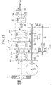
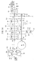
- the shift control is performed according to a shift control system illustrated in Fig. 16. Also in a seventh and eighth embodiments which will be described hereinafter, the same shift control system is applied.
- the main clutch 91, the sub clutch 27, the lock-up clutch 93 and the hydraulic actuators 33 are operated according to control signals from the shift control section 31.
- the main clutch 91, the sub clutch 27, the lock-up clutch 93 and the synchromesh mechanism 16, 17 and 18 are in the following engagement condition when a selector lever is positioned at D (forward traveling) range.
- the synchromesh mechanism 16 is shifted toward the 1st speed drive gear to select the 1st gear position.
- the main clutch 91 is engaged by hydraulic pressure fed from the hydraulic circuit 32 while the lock-up clutch 93 is released.
- the power of the engine is transmitted to the input shaft 1 through the torque converter 92, the main clutch 91 and the vehicle starts to travel.
- the gear is up-shifted successively according to the shift schedule programmed in the shift control section 31.
- the lock-up clutch 93 is engaged at a speed range higher than a specified vehicle speed.
- the torque of the sub clutch 27 is controlled in the same manner as described in the first and fourth embodiments. Also in the seventh and eighth embodiments, the sub clutch 27 is controlled similarly.
- the torque converter 92 is used as a power transmitting means connecting the engine and the automatic transmission, the torque amplifying effect of the torque converter 92 can be expected. That is, unless the torque converter is employed, in case where the vehicle starts on an upgrade while towing or tries to escape from rough roads, the main clutch is subjected to heat and abrasion repeatedly, and this leads to a problem of endurance of the clutch. Up-sizing of the main clutch produces an increase of inertia which provides overloads on the synchromesh mechanisms . On the other hand, if the torque converter is employed as in this embodiment, since the power of the engine is amplified by the torque converter, a large driving force can be secured, thereby good maneuverability is obtained.
- Fig. 14 is a skeleton diagram showing a five forward speed automatic transmission according to a seventh embodiment.
- This automatic transmission has the same structure as the transmission according to the fifth embodiment except for the power transmission mechanism 90. Further, the power transmission mechanism 90 has the same structure as the one described in the sixth embodiment. Accordingly, the automatic transmission of this embodiment has both effects and features described in the fifth and sixth embodiments.
- Fig. 15 is a skeleton diagram showing a five forward speed automatic transmission according to an eighth embodiment of the present invention.
- This transmission is the same as that described in the first embodiment excepting the main clutch 5.
- the main clutch 5 is replaced with the power transmission mechanism 90 described in the sixth embodiment. Accordingly, this automatic transmission has advantages of using a torque converter in addition to the advantages provided by the first embodiment.
Landscapes
- Engineering & Computer Science (AREA)
- General Engineering & Computer Science (AREA)
- Mechanical Engineering (AREA)
- Structure Of Transmissions (AREA)
- Control Of Transmission Device (AREA)
Applications Claiming Priority (6)
| Application Number | Priority Date | Filing Date | Title |
|---|---|---|---|
| JP2000034878A JP2001227599A (ja) | 2000-02-14 | 2000-02-14 | 自動変速機 |
| JP2000035066 | 2000-02-14 | ||
| JP2000034878 | 2000-02-14 | ||
| JP2000035066A JP2001227600A (ja) | 2000-02-14 | 2000-02-14 | 自動変速機 |
| JP2000045405 | 2000-02-23 | ||
| JP2000045405A JP2001234989A (ja) | 2000-02-23 | 2000-02-23 | 自動変速機 |
Publications (2)
| Publication Number | Publication Date |
|---|---|
| EP1126192A2 true EP1126192A2 (de) | 2001-08-22 |
| EP1126192A3 EP1126192A3 (de) | 2006-01-11 |
Family
ID=27342347
Family Applications (1)
| Application Number | Title | Priority Date | Filing Date |
|---|---|---|---|
| EP01103330A Withdrawn EP1126192A3 (de) | 2000-02-14 | 2001-02-13 | Automatisches Getriebe |
Country Status (2)
| Country | Link |
|---|---|
| US (1) | US6647817B2 (de) |
| EP (1) | EP1126192A3 (de) |
Cited By (1)
| Publication number | Priority date | Publication date | Assignee | Title |
|---|---|---|---|---|
| DE10313585B4 (de) * | 2002-03-27 | 2006-02-23 | Suzuki Motor Corp., Hamamatsu | Automatisches Schaltgetriebe |
Families Citing this family (16)
| Publication number | Priority date | Publication date | Assignee | Title |
|---|---|---|---|---|
| US7222551B2 (en) * | 2000-04-25 | 2007-05-29 | Hitachi, Ltd. | Automatic transmission |
| JP2001311466A (ja) * | 2000-04-28 | 2001-11-09 | Fuji Heavy Ind Ltd | 変速制御装置 |
| EP1190888A3 (de) | 2000-09-20 | 2006-02-15 | Fuji Jukogyo Kabushiki Kaisha | Fahrzeuggetriebesystem mit Antriebskupplung |
| JP2002206639A (ja) * | 2000-11-08 | 2002-07-26 | Hitachi Ltd | 自動変速機及び車両 |
| DE10120060A1 (de) * | 2001-04-24 | 2002-10-31 | Zahnradfabrik Friedrichshafen | Fahrzeuggetriebe |
| JP3891823B2 (ja) * | 2001-10-31 | 2007-03-14 | 本田技研工業株式会社 | 変速機 |
| JP2003278913A (ja) | 2002-03-27 | 2003-10-02 | Suzuki Motor Corp | 車両用自動変速装置 |
| JP2003278902A (ja) | 2002-03-27 | 2003-10-02 | Suzuki Motor Corp | 車両用自動変速制御装置 |
| JP2003278898A (ja) | 2002-03-27 | 2003-10-02 | Suzuki Motor Corp | 自動変速機 |
| KR100828673B1 (ko) * | 2005-12-21 | 2008-05-09 | 현대자동차주식회사 | 6속 수동 변속기 |
| JP5121654B2 (ja) * | 2008-10-06 | 2013-01-16 | ヤマハ発動機株式会社 | 変速制御システムおよび車両 |
| JP5501083B2 (ja) * | 2010-04-28 | 2014-05-21 | アイシン・エーアイ株式会社 | 車両の動力伝達制御装置 |
| CN109866613B (zh) * | 2017-12-04 | 2020-11-03 | 华为技术有限公司 | 减速器、电动汽车的驱动系统及其控制方法、电动汽车 |
| CN109723768A (zh) * | 2019-01-04 | 2019-05-07 | 清华大学苏州汽车研究院(吴江) | 基于一轴耦合电机实现amt变速箱动力换档系统及方法 |
| US11834998B2 (en) * | 2019-04-18 | 2023-12-05 | Hamilton Sundstrand Corporation | Transmission systems having clutch at output side |
| US11460093B2 (en) * | 2020-10-28 | 2022-10-04 | Dana Automotive Systems Group, Llc | Vehicle system with multi-speed transmission |
Citations (3)
| Publication number | Priority date | Publication date | Assignee | Title |
|---|---|---|---|---|
| JPS58149443A (ja) | 1982-02-27 | 1983-09-05 | Toyota Motor Corp | 歯車式変速機 |
| JPS6145163A (ja) | 1984-08-10 | 1986-03-05 | Hitachi Ltd | 自動変速システム |
| JP2703169B2 (ja) | 1993-08-27 | 1998-01-26 | 株式会社日立製作所 | 自動車の自動変速装置及び自動変速方法 |
Family Cites Families (7)
| Publication number | Priority date | Publication date | Assignee | Title |
|---|---|---|---|---|
| GB1349936A (en) * | 1970-09-23 | 1974-04-10 | Brown Gear Ind | Change-speed gear-boxes |
| US3916714A (en) * | 1973-08-27 | 1975-11-04 | Clark Equipment Co | Transmissions |
| JPS632735A (ja) * | 1986-06-20 | 1988-01-07 | Toyota Motor Corp | 車両用自動変速装置 |
| DE4236515A1 (en) * | 1991-11-11 | 1993-05-13 | Volkswagen Ag | Five speed gear box for vehicle - has arrangement of couplings to facilitate change-down during descent |
| JPH0914420A (ja) * | 1995-06-23 | 1997-01-14 | Aqueous Res:Kk | 自動変速機 |
| JP3660528B2 (ja) * | 1999-06-07 | 2005-06-15 | 本田技研工業株式会社 | 平行軸式変速機 |
| JP2001311466A (ja) * | 2000-04-28 | 2001-11-09 | Fuji Heavy Ind Ltd | 変速制御装置 |
-
2001
- 2001-02-09 US US09/780,181 patent/US6647817B2/en not_active Expired - Fee Related
- 2001-02-13 EP EP01103330A patent/EP1126192A3/de not_active Withdrawn
Patent Citations (3)
| Publication number | Priority date | Publication date | Assignee | Title |
|---|---|---|---|---|
| JPS58149443A (ja) | 1982-02-27 | 1983-09-05 | Toyota Motor Corp | 歯車式変速機 |
| JPS6145163A (ja) | 1984-08-10 | 1986-03-05 | Hitachi Ltd | 自動変速システム |
| JP2703169B2 (ja) | 1993-08-27 | 1998-01-26 | 株式会社日立製作所 | 自動車の自動変速装置及び自動変速方法 |
Cited By (1)
| Publication number | Priority date | Publication date | Assignee | Title |
|---|---|---|---|---|
| DE10313585B4 (de) * | 2002-03-27 | 2006-02-23 | Suzuki Motor Corp., Hamamatsu | Automatisches Schaltgetriebe |
Also Published As
| Publication number | Publication date |
|---|---|
| US6647817B2 (en) | 2003-11-18 |
| US20010013258A1 (en) | 2001-08-16 |
| EP1126192A3 (de) | 2006-01-11 |
Similar Documents
| Publication | Publication Date | Title |
|---|---|---|
| US6647817B2 (en) | Automatic transmission | |
| CN102083645B (zh) | 车辆驱动系统 | |
| EP2126411B1 (de) | Fahrzeuggetriebe mit mehrgang-doppelkupplung | |
| US5014566A (en) | Automatic transmission for a motor vehicle | |
| GB2443523A (en) | Transmission control method providing rock-cycling and blended gear shifts | |
| JP2007331654A (ja) | パーキングロック機能を備えた歯車変速装置 | |
| US9145928B2 (en) | Transmission with rear torque converter | |
| US6648795B2 (en) | Transmission system for vehicle | |
| US4960005A (en) | Automatic transmission for a motor vehicle | |
| US6655226B2 (en) | Automatic transmission | |
| EP0444497B1 (de) | Getriebe mit extrem niedrigem Geschwindigkeitbereich | |
| JP2007332991A (ja) | 歯車変速装置 | |
| EP0159141A2 (de) | Mehrgängiges Schaltgetriebe | |
| EP1347203B1 (de) | Schaltgetriebe für vierradgetriebenes Fahrzeug | |
| US20040266584A1 (en) | Method for controlling speed ratio changes in a layshaft automatic transmission having power-on shifting | |
| US9249882B2 (en) | Dual clutch transmission | |
| EP0034412A2 (de) | Getriebe für drehbare Leistung | |
| JP2001227599A (ja) | 自動変速機 | |
| JP2001234989A (ja) | 自動変速機 | |
| JP2001227600A (ja) | 自動変速機 | |
| US20260002579A1 (en) | Power-shift transmission for a motor vehicle transmission of the range change type | |
| JPH0546456B2 (de) | ||
| KR100992792B1 (ko) | 더블 클러치식 수동변속기 | |
| JP2009216114A (ja) | 四輪駆動車両の変速装置 | |
| JPS61274142A (ja) | 歯車式変速装置 |
Legal Events
| Date | Code | Title | Description |
|---|---|---|---|
| PUAI | Public reference made under article 153(3) epc to a published international application that has entered the european phase |
Free format text: ORIGINAL CODE: 0009012 |
|
| AK | Designated contracting states |
Kind code of ref document: A2 Designated state(s): AT BE CH CY DE DK ES FI FR GB GR IE IT LI LU MC NL PT SE TR |
|
| AX | Request for extension of the european patent |
Free format text: AL;LT;LV;MK;RO;SI |
|
| PUAL | Search report despatched |
Free format text: ORIGINAL CODE: 0009013 |
|
| AK | Designated contracting states |
Kind code of ref document: A3 Designated state(s): AT BE CH CY DE DK ES FI FR GB GR IE IT LI LU MC NL PT SE TR |
|
| AX | Request for extension of the european patent |
Extension state: AL LT LV MK RO SI |
|
| RIC1 | Information provided on ipc code assigned before grant |
Ipc: F16H 61/04 20060101ALI20051124BHEP Ipc: F16H 3/12 20060101AFI20010509BHEP |
|
| 17P | Request for examination filed |
Effective date: 20060324 |
|
| AKX | Designation fees paid |
Designated state(s): DE FR GB |
|
| 17Q | First examination report despatched |
Effective date: 20061123 |
|
| STAA | Information on the status of an ep patent application or granted ep patent |
Free format text: STATUS: THE APPLICATION HAS BEEN WITHDRAWN |
|
| 18W | Application withdrawn |
Effective date: 20070315 |