EP1126227A1 - Condenseur de vapeur - Google Patents
Condenseur de vapeur Download PDFInfo
- Publication number
- EP1126227A1 EP1126227A1 EP00810112A EP00810112A EP1126227A1 EP 1126227 A1 EP1126227 A1 EP 1126227A1 EP 00810112 A EP00810112 A EP 00810112A EP 00810112 A EP00810112 A EP 00810112A EP 1126227 A1 EP1126227 A1 EP 1126227A1
- Authority
- EP
- European Patent Office
- Prior art keywords
- steam
- condenser
- modules
- space
- neck
- Prior art date
- Legal status (The legal status is an assumption and is not a legal conclusion. Google has not performed a legal analysis and makes no representation as to the accuracy of the status listed.)
- Withdrawn
Links
- 238000001816 cooling Methods 0.000 claims abstract description 6
- XLYOFNOQVPJJNP-UHFFFAOYSA-N water Substances O XLYOFNOQVPJJNP-UHFFFAOYSA-N 0.000 claims description 13
- 239000000498 cooling water Substances 0.000 claims description 4
- 238000004519 manufacturing process Methods 0.000 description 5
- 238000005452 bending Methods 0.000 description 4
- 239000003990 capacitor Substances 0.000 description 4
- 230000007797 corrosion Effects 0.000 description 3
- 238000005260 corrosion Methods 0.000 description 3
- 230000003628 erosive effect Effects 0.000 description 3
- 230000000052 comparative effect Effects 0.000 description 1
- 238000010276 construction Methods 0.000 description 1
- 238000001704 evaporation Methods 0.000 description 1
- 230000008020 evaporation Effects 0.000 description 1
- 230000037431 insertion Effects 0.000 description 1
- 238000003780 insertion Methods 0.000 description 1
- 238000009434 installation Methods 0.000 description 1
- 230000001788 irregular Effects 0.000 description 1
- 239000000725 suspension Substances 0.000 description 1
- 238000011179 visual inspection Methods 0.000 description 1
Images


Classifications
-
- F—MECHANICAL ENGINEERING; LIGHTING; HEATING; WEAPONS; BLASTING
- F28—HEAT EXCHANGE IN GENERAL
- F28B—STEAM OR VAPOUR CONDENSERS
- F28B1/00—Condensers in which the steam or vapour is separate from the cooling medium by walls, e.g. surface condenser
- F28B1/02—Condensers in which the steam or vapour is separate from the cooling medium by walls, e.g. surface condenser using water or other liquid as the cooling medium
Definitions
- the invention relates to a steam condenser in a steam power plant or Combined system, which is arranged at ground level with the turbine and to which the Turbine steam flows in a horizontal direction through a condenser neck.
- the steam condenser has several elongated and horizontal stored tube bundles, each separated by a central aisle are spaced and through which the steam flows into the tube bundle.
- a device arranged for the introduction of steam, from the boiler of the power plant via a bypass line directly into the Condenser is passed.
- Such a steam condenser with horizontal steam inflow is described for example in EP 0 384 200. It has several elongated and horizontally arranged bundles of pipes through which the cooling water flows.
- the steam flows in from the turbine in a horizontal direction via the condenser neck into the Mittelgasse and from there into the interior of the tube bundle, where the steam condenses.
- the condensate that forms on the pipes flows down through condensate collecting plates into a hotwell in the area of the bottom of the condenser.
- such a steam condenser is of modular construction, with each module containing, for example, two tube bundles, between which there is a free space or a central lane through which the steam can reach the cooling tubes in the tube bundles.
- the modules are arranged one above the other, their central, horizontal module walls, which face an adjacent module, being connected to one another by assembly weld seams.
- the condensate that accumulates in the tube bundles of the upper module flows to an opening at the bottom of that module. From there it finally gets into the lower module and into the hotwell of the capacitor.
- the welded connection between the middle module walls bears the risk that a gap can occur along these module walls due to manufacturing tolerances. As a result, the contact areas there are irregular and there are uneven tensions. These can lead to leaks and create a risk of corrosion, especially in the area of the drain opening for the condensate from the upper to the lower module. Since the module walls lie directly on top of each other, this corrosion cannot be inspected visually and a repair can be arranged if necessary.
- a steam bypass station When starting up and shutting down a power plant and when shedding loads, steam from the boiler is fed directly to the condenser via a steam bypass station for operational safety and to reduce losses.
- a diversion station typically consists of two to three bypass lines that bypass the turbine and a steam introduction device in the condenser neck.
- the mass flows through the diversion station are often greater than the turbine steam flow during normal turbine operation, especially in combination systems. Since the cross-sections of the bypass lines are much smaller than the cross-section of the turbine evaporation nozzle, there are very highly concentrated steam flows in the bypass lines.
- the steam in the steam introduction device also flows at supersonic speeds, which can lead to erosion damage to components in the condenser.
- the space available at the condenser neck is partially restricted, since other systems must also be placed there.
- the pipeline planning for the bypass lines is therefore cumbersome, and the placement of the insertion device on the condenser neck is difficult to optimize with regard to the flow dynamics.
- a steam condenser according to claim 1.
- the stacked modules of the steam condenser are spaced from each other according to the invention by between the adjacent Modules there is a defined space, between the walls of the two modules facing each other are several connecting parts are arranged.
- the spacing of the modules provides one Facilitation of manufacture by manufacturing both or all modules identically and can be connected to each other by the connecting parts. Are there the number of necessary welds is also considerably reduced.
- the connecting parts serve both to define the space between the Modules as well as the support of the modules and thereby provide the advantage that the stress distribution in the middle module walls is defined as it were is. The tensions are no longer affected by the manufacturing tolerances influenced.
- the neighboring modules are also each through a connection channel connected in order to drain the condensate, which is in a top arranged module occurs through a condensate drain opening in the bottom of that Module flows into the module below.
- the space between the modules is below atmospheric pressure.
- the The space is enclosed by side walls and is connected to the Steam room under vacuum.
- the first execution of the space below Atmospheric pressure has the comparative advantage that the support of the Modules requires fewer components and is therefore easier to implement.
- the second version on the other hand, has the advantage of being a simpler one Drainage of the upper module without several individual connection channels enables.
- the middle ones are horizontal lying and facing module walls arranged at the height, so that they are level with the cylindrical walls of the water chambers lie.
- This arrangement carries the pressure forces from the Water chambers advantageous at. This prevents bending moments which otherwise from the pressure from the water chambers on the middle module walls arise. Tie rods or bracing ribs that are otherwise used for the intake such bending moments are no longer required, so Manufacturing and assembly costs can be saved.
- the connecting parts or tabs on openings used as transport hangers can be.
- the space is used for placement used by bypass lines.
- all bypass lines from same side of the capacitor in the space and from there to one Steam introduction device guided on the condenser neck.
- the gap thereby enables a greatly simplified line arrangement, whereby the Lines are shorter and similar flow conditions in all lines prevalence.
- the steam introduction device is arranged at the level of the gap. This has the advantage that the steam introduction device does not hinder the flow of turbine steam into the condenser, since it lies in a "dead" zone with respect to this steam flow.
- the steam introduction device has a perforated bypass manifold with a plurality of pipe pieces, which extends over the entire width of the condenser neck. A bypass line leads to each of these pipe sections. Each piece of pipe has several rows of openings or apertures through which the bypass steam enters the condenser neck.
- the perforated bypass manifold is on the one hand in the same direction as the cooling water pipes of the condenser, on the other hand at the level of the Intermediate space where there are no cooling tubes. Behind her So there is only the gap, so there are no negative eddies arise, which impede the turbine steam flow to the cooling tubes would.
- the multi-row aperture holes over the entire length of the Bypass manifold and so over the entire width of the condenser neck also has the advantage that the bypass steam is so relaxed that the Risk of erosion on components in the condenser and condenser neck the bypass steam is reduced.
- FIG. 1 shows a steam condenser 1 which is arranged at ground level with respect to a turbine 2 and is connected to it by a condenser neck 3.
- the steam condenser 1 is constructed from two or more identical modules arranged one above the other, two modules 4a, 4b being present in the exemplary embodiment shown.
- the modules 4a, 4b each have two elongated, horizontally oriented tube bundles 5, between which there is a central alley or Damfeinströmgasse.
- the steam space of each module 4a, 4b is enclosed by a steam jacket 6.
- the two modules 4a, 4b are spaced apart from one another by an intermediate space 7, connecting parts 8 being arranged between the two modules and connecting and supporting the middle module walls 9 of the modules 4a, 4b. This connection and support results in a defined stress distribution in these middle module walls 9.
- the water chambers and deflection chambers for the cooling water of each tube bundle are, for example, hemispherical. (You are not in this figure drawn in and described below in connection with FIG. 2.)
- the steam from the turbine 2 flows through the horizontal Condenser neck 3 to the steam condenser 1 and initially flows there into the Middle aisles of the two modules 4a, 4b and from there into the tube bundle 5, where it starts the tubes 10 condensed.
- the condensate in the module 4a accumulates, flows to the bottom of this module and there a condensate drain opening to, which opens into a connecting channel 11. This causes the condensate to get through finally into the module 4b below, where it is together with the there accumulating condensate is collected in Hotwell 12.
- Figure 2 shows the space 7 with the connecting parts 8 and Connection channel 11.
- the connecting parts 8 consist, for example, of several Individual pieces that are distributed across the width of the modules. They serve together with the connection channel 11 of the support of the upper module.
- the connecting parts 8 have openings or eyes 13 for transport purposes which are used in a crane suspension.
- Connecting parts have a double use, that of connection and support during operation and that of the transport and installation aid.
- the space 7 is in the embodiment shown here under atmospheric Print.
- the space is under vacuum, with the Interspace communicates with the steam room of the two modules.
- the connection of the two modules requires additional side walls, which are welded to the side walls of the modules. This variant enables a more direct drainage of the upper module without individual Connecting channels.
- water chambers 14 are with respect to the modules 4a and 4b arranged in this way (the module 4a is not here for better illustration shown) that the semi-cylindrical walls 15 of the water chambers 14th are at the same height as the middle walls 9 of the modules. That means the Jacket 15 of the semi-cylindrical water chambers 14 is in each case with the module 4b connected at the level of the middle module wall 9. This will make the Pressure forces emanating from the water chambers through the middle walls 9 added. In particular, none are created in the middle walls 9 Bending moments, so that no additional bracing ribs or tie rods must be installed to absorb these bending moments.
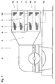
- FIG 3 shows in section the steam condenser 1 with two modules 4a, 4b are spaced from one another by the intermediate space 7.
- one or more bypass lines 20 are guided, of which in this section one of them can be seen.
- the bypass lines lead from (not shown) Bypassing the turbine bypassing the condenser neck 3 and there a steam introduction device 21.
- this is at the height of the intermediate space 7, that is to say positioned between the two modules 4a and 4b.
- the steam inflow 22 from the turbine 2 into the condenser 1 is through this Positioning of the steam introduction device 21 is not hindered. In the area the cooling pipes therefore do not create any negative eddies or so-called Karman Whirlwinds.
- the steam introduction device has one Steam collecting line 21, that is on its upper and lower side, that is on both sides of the gap 7, a variety of outflow or Has aperture openings 23.
- the bypass steam flow from the bypass lines 20 is relaxed in the manifolds 21 and then passes through the Openings 23 in the condenser neck 3.
- the outflow area 24 of the Bypass steam is indicated by dashed lines. He is compared to conventional steam introducers wider, which helps the inflow speed of the bypass steam is lower and the erosion is increased Components in the capacitor is reduced.
- the middle module walls 9 each have openings 25 which run into the drain of the condensate 26 from the upper module 4a through the connection channel 11 in the lower module 4b serve. From there the condensate gets together with the Finally, condensate from the lower module here into Hotwell 12.
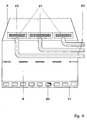
- FIG. 4 shows, in a further section through the intermediate space, the arrangement of three bypass lines 20. All lines lead from the same side of the capacitor through the intermediate space 7 into the condenser neck 3. This arrangement enables the use of shorter and similarly designed and therefore more cost-effective lines. The assembly of lines in this arrangement is also facilitated.
- three steam collecting lines 21 are arranged, which are arranged uniformly distributed over the width of the condenser neck 3.
- Each bypass line 20 leads to an associated steam manifold 21.
- Each manifold 21 has a number of rows of outflow openings 23 over its entire length, through which the bypass steam flows into the condenser neck. In the example shown, these are circular openings.
- the plurality of condensate drain openings 25 are arranged here, for example, over the entire width of the connecting channel 11.
Landscapes
- Engineering & Computer Science (AREA)
- Mechanical Engineering (AREA)
- General Engineering & Computer Science (AREA)
- Heat-Exchange Devices With Radiators And Conduit Assemblies (AREA)
- Details Of Heat-Exchange And Heat-Transfer (AREA)
Priority Applications (4)
| Application Number | Priority Date | Filing Date | Title |
|---|---|---|---|
| EP00810112A EP1126227A1 (fr) | 2000-02-09 | 2000-02-09 | Condenseur de vapeur |
| CA002334559A CA2334559A1 (fr) | 2000-02-09 | 2001-02-06 | Condenseur de vapeur |
| HU0100633A HUP0100633A2 (hu) | 2000-02-09 | 2001-02-08 | Gőzkondenzátor |
| US09/779,663 US6360543B2 (en) | 2000-02-09 | 2001-02-09 | Steam condenser |
Applications Claiming Priority (1)
| Application Number | Priority Date | Filing Date | Title |
|---|---|---|---|
| EP00810112A EP1126227A1 (fr) | 2000-02-09 | 2000-02-09 | Condenseur de vapeur |
Publications (1)
| Publication Number | Publication Date |
|---|---|
| EP1126227A1 true EP1126227A1 (fr) | 2001-08-22 |
Family
ID=8174545
Family Applications (1)
| Application Number | Title | Priority Date | Filing Date |
|---|---|---|---|
| EP00810112A Withdrawn EP1126227A1 (fr) | 2000-02-09 | 2000-02-09 | Condenseur de vapeur |
Country Status (4)
| Country | Link |
|---|---|
| US (1) | US6360543B2 (fr) |
| EP (1) | EP1126227A1 (fr) |
| CA (1) | CA2334559A1 (fr) |
| HU (1) | HUP0100633A2 (fr) |
Families Citing this family (7)
| Publication number | Priority date | Publication date | Assignee | Title |
|---|---|---|---|---|
| US7124580B2 (en) | 2004-06-22 | 2006-10-24 | Crown Iron Works Company | Sub-zero condensation vacuum system |
| US8286430B2 (en) * | 2009-05-28 | 2012-10-16 | General Electric Company | Steam turbine two flow low pressure configuration |
| US8813500B2 (en) * | 2011-08-03 | 2014-08-26 | Dresser-Rand Company | Combined heat exchanger expander mounting system |
| JP6221168B2 (ja) * | 2013-03-27 | 2017-11-01 | 三菱日立パワーシステムズ株式会社 | 復水器、及びこれを備える蒸気タービンプラント |
| WO2015111318A1 (fr) * | 2014-01-23 | 2015-07-30 | 三菱日立パワーシステムズ株式会社 | Condenseur |
| WO2017145404A1 (fr) * | 2016-02-25 | 2017-08-31 | 三菱日立パワーシステムズ株式会社 | Condenseur et installation de turbine à vapeur pourvue de celui-ci |
| CN113295019A (zh) * | 2021-05-11 | 2021-08-24 | 于都县正亿纸品纸业有限公司 | 一种蒸汽回收装置 |
Citations (7)
| Publication number | Priority date | Publication date | Assignee | Title |
|---|---|---|---|---|
| CH414682A (de) * | 1962-08-23 | 1966-06-15 | Ass Elect Ind | Dampfturbinenanlage |
| US4253516A (en) * | 1978-06-22 | 1981-03-03 | Westinghouse Electric Corp. | Modular heat exchanger |
| EP0128452A1 (fr) * | 1983-06-03 | 1984-12-19 | Delas-Weir | Faisceau tubulaire modulaire pour condenseur de vapeur et condenseur de vapeur en faisant application |
| EP0384200A1 (fr) | 1989-02-23 | 1990-08-29 | Asea Brown Boveri Ag | Condenseur à vapeur |
| EP0594499A1 (fr) * | 1992-10-21 | 1994-04-27 | Gec Alsthom Electromecanique Sa | Condenseur en béton pour turbine à vapeur à échappement axial avec montage simplifié des faisceaux |
| WO1998015720A1 (fr) * | 1996-10-08 | 1998-04-16 | Siemens Aktiengesellschaft | Systeme de turbine a vapeur |
| EP0957325A1 (fr) * | 1998-05-14 | 1999-11-17 | Asea Brown Boveri AG | Condenseur de vapeur |
Family Cites Families (4)
| Publication number | Priority date | Publication date | Assignee | Title |
|---|---|---|---|---|
| DE2107013A1 (de) * | 1971-02-13 | 1972-08-17 | Kraftwerk Union Ag | Kondensationsanlage für den Abdampf von Dampfkraftwerken |
| US3881548A (en) * | 1971-07-14 | 1975-05-06 | Westinghouse Electric Corp | Multi-temperature circulating water system for a steam turbine |
| US4059959A (en) * | 1976-11-05 | 1977-11-29 | Sperry Rand Corporation | Geothermal energy processing system with improved heat rejection |
| US4747360A (en) * | 1983-06-24 | 1988-05-31 | General Electric Company | Condenser integrated turbine support |
-
2000
- 2000-02-09 EP EP00810112A patent/EP1126227A1/fr not_active Withdrawn
-
2001
- 2001-02-06 CA CA002334559A patent/CA2334559A1/fr not_active Abandoned
- 2001-02-08 HU HU0100633A patent/HUP0100633A2/hu unknown
- 2001-02-09 US US09/779,663 patent/US6360543B2/en not_active Expired - Fee Related
Patent Citations (7)
| Publication number | Priority date | Publication date | Assignee | Title |
|---|---|---|---|---|
| CH414682A (de) * | 1962-08-23 | 1966-06-15 | Ass Elect Ind | Dampfturbinenanlage |
| US4253516A (en) * | 1978-06-22 | 1981-03-03 | Westinghouse Electric Corp. | Modular heat exchanger |
| EP0128452A1 (fr) * | 1983-06-03 | 1984-12-19 | Delas-Weir | Faisceau tubulaire modulaire pour condenseur de vapeur et condenseur de vapeur en faisant application |
| EP0384200A1 (fr) | 1989-02-23 | 1990-08-29 | Asea Brown Boveri Ag | Condenseur à vapeur |
| EP0594499A1 (fr) * | 1992-10-21 | 1994-04-27 | Gec Alsthom Electromecanique Sa | Condenseur en béton pour turbine à vapeur à échappement axial avec montage simplifié des faisceaux |
| WO1998015720A1 (fr) * | 1996-10-08 | 1998-04-16 | Siemens Aktiengesellschaft | Systeme de turbine a vapeur |
| EP0957325A1 (fr) * | 1998-05-14 | 1999-11-17 | Asea Brown Boveri AG | Condenseur de vapeur |
Also Published As
| Publication number | Publication date |
|---|---|
| US20010011458A1 (en) | 2001-08-09 |
| HU0100633D0 (en) | 2001-04-28 |
| HUP0100633A2 (hu) | 2002-07-29 |
| CA2334559A1 (fr) | 2001-08-09 |
| US6360543B2 (en) | 2002-03-26 |
Similar Documents
| Publication | Publication Date | Title |
|---|---|---|
| EP1642075B1 (fr) | Conduite de vapeur d'echappement pour dispositifs a vapeur | |
| EP3201550B1 (fr) | Installation pour la condensation de vapeur | |
| EP2304370A1 (fr) | Jeu d adaptation pour un échangeur de chaleur à faisceau tubulaire | |
| DE1501618C3 (de) | Wärmeübertrager | |
| DE1601127B2 (de) | Kühlanlage mit einem mit natürlichem Zug arbeitenden Kühlturm | |
| EP0768424A2 (fr) | Cylindre chauffant | |
| DE202014104666U1 (de) | Anlage zur Kondensation von Dampf | |
| EP0069262A1 (fr) | Dispositif, dans lequel la chaleur est transmise à travers des fibres creuses | |
| EP0619466B1 (fr) | Condenseur de vapeur | |
| DE1932027A1 (de) | Waermetauscher | |
| EP1189005A1 (fr) | Col de condensation entre une turbine a vapeur et une condensateur | |
| DE1939245C3 (de) | Luftgekühlter Kondensator für das Kopf produkt einer Destillier- oder Rektifizier-Kolonne | |
| DE1942433C3 (de) | Brennelement für Kernreaktoren | |
| EP3134676B1 (fr) | Échangeur de chaleur | |
| DE2711545C2 (de) | Wärmetauscher mit einer Vielzahl von Geradrohrbündeln | |
| DE2158920A1 (de) | Vorrichtung zur Dampftrocknung und -überhitzung | |
| DE1451270C3 (de) | Wärmeübertrager einer Kernreaktoranlage | |
| DE1514501B2 (de) | Kernreaktoranlage mit Dampferzeuger | |
| EP4235074B1 (fr) | Echangeur de chaleur | |
| DE2816293A1 (de) | Kuehlturm | |
| DE2541200A1 (de) | Brennelement fuer mit leicht- oder schwerwasser gekuehlte atomkernreaktoren | |
| EP0957325A1 (fr) | Condenseur de vapeur | |
| DE3621461C2 (fr) | ||
| DE2415137A1 (de) | Dampftrockner - ueberhitzer | |
| EP1174672A2 (fr) | Centrale combinée ou à vapeur |
Legal Events
| Date | Code | Title | Description |
|---|---|---|---|
| PUAI | Public reference made under article 153(3) epc to a published international application that has entered the european phase |
Free format text: ORIGINAL CODE: 0009012 |
|
| AK | Designated contracting states |
Kind code of ref document: A1 Designated state(s): AT BE CH CY DE DK ES FI FR GB GR IE IT LI LU MC NL PT SE |
|
| AX | Request for extension of the european patent |
Free format text: AL;LT;LV;MK;RO;SI |
|
| RAP1 | Party data changed (applicant data changed or rights of an application transferred) |
Owner name: ALSTOM (SWITZERLAND) LTD |
|
| 17P | Request for examination filed |
Effective date: 20020118 |
|
| RAP1 | Party data changed (applicant data changed or rights of an application transferred) |
Owner name: ALSTOM (SWITZERLAND) LTD |
|
| AKX | Designation fees paid |
Free format text: DE ES FR GB IT |
|
| STAA | Information on the status of an ep patent application or granted ep patent |
Free format text: STATUS: THE APPLICATION HAS BEEN WITHDRAWN |
|
| 18W | Application withdrawn |
Effective date: 20030613 |