EP0594499A1 - Condenseur en béton pour turbine à vapeur à échappement axial avec montage simplifié des faisceaux - Google Patents
Condenseur en béton pour turbine à vapeur à échappement axial avec montage simplifié des faisceaux Download PDFInfo
- Publication number
- EP0594499A1 EP0594499A1 EP93402568A EP93402568A EP0594499A1 EP 0594499 A1 EP0594499 A1 EP 0594499A1 EP 93402568 A EP93402568 A EP 93402568A EP 93402568 A EP93402568 A EP 93402568A EP 0594499 A1 EP0594499 A1 EP 0594499A1
- Authority
- EP
- European Patent Office
- Prior art keywords
- condenser
- plates
- concrete
- bundles
- walls
- Prior art date
- Legal status (The legal status is an assumption and is not a legal conclusion. Google has not performed a legal analysis and makes no representation as to the accuracy of the status listed.)
- Granted
Links
- 229910000831 Steel Inorganic materials 0.000 claims abstract description 6
- 239000010959 steel Substances 0.000 claims abstract description 6
- XLYOFNOQVPJJNP-UHFFFAOYSA-N water Substances O XLYOFNOQVPJJNP-UHFFFAOYSA-N 0.000 claims description 5
- 238000012423 maintenance Methods 0.000 abstract description 2
- 238000006073 displacement reaction Methods 0.000 description 2
- 230000000712 assembly Effects 0.000 description 1
- 238000000429 assembly Methods 0.000 description 1
Images
Classifications
-
- F—MECHANICAL ENGINEERING; LIGHTING; HEATING; WEAPONS; BLASTING
- F01—MACHINES OR ENGINES IN GENERAL; ENGINE PLANTS IN GENERAL; STEAM ENGINES
- F01K—STEAM ENGINE PLANTS; STEAM ACCUMULATORS; ENGINE PLANTS NOT OTHERWISE PROVIDED FOR; ENGINES USING SPECIAL WORKING FLUIDS OR CYCLES
- F01K11/00—Plants characterised by the engines being structurally combined with boilers or condensers
- F01K11/02—Plants characterised by the engines being structurally combined with boilers or condensers the engines being turbines
-
- F—MECHANICAL ENGINEERING; LIGHTING; HEATING; WEAPONS; BLASTING
- F28—HEAT EXCHANGE IN GENERAL
- F28B—STEAM OR VAPOUR CONDENSERS
- F28B1/00—Condensers in which the steam or vapour is separate from the cooling medium by walls, e.g. surface condenser
- F28B1/02—Condensers in which the steam or vapour is separate from the cooling medium by walls, e.g. surface condenser using water or other liquid as the cooling medium
-
- F—MECHANICAL ENGINEERING; LIGHTING; HEATING; WEAPONS; BLASTING
- F28—HEAT EXCHANGE IN GENERAL
- F28F—DETAILS OF HEAT-EXCHANGE AND HEAT-TRANSFER APPARATUS, OF GENERAL APPLICATION
- F28F9/00—Casings; Header boxes; Auxiliary supports for elements; Auxiliary members within casings
- F28F9/007—Auxiliary supports for elements
- F28F9/013—Auxiliary supports for elements for tubes or tube-assemblies
-
- Y—GENERAL TAGGING OF NEW TECHNOLOGICAL DEVELOPMENTS; GENERAL TAGGING OF CROSS-SECTIONAL TECHNOLOGIES SPANNING OVER SEVERAL SECTIONS OF THE IPC; TECHNICAL SUBJECTS COVERED BY FORMER USPC CROSS-REFERENCE ART COLLECTIONS [XRACs] AND DIGESTS
- Y10—TECHNICAL SUBJECTS COVERED BY FORMER USPC
- Y10S—TECHNICAL SUBJECTS COVERED BY FORMER USPC CROSS-REFERENCE ART COLLECTIONS [XRACs] AND DIGESTS
- Y10S165/00—Heat exchange
- Y10S165/051—Heat exchange having expansion and contraction relieving or absorbing means
- Y10S165/052—Heat exchange having expansion and contraction relieving or absorbing means for cylindrical heat exchanger
- Y10S165/053—Flexible or movable header or header element
- Y10S165/058—Movable tubesheet, e.g. floating tubesheet
- Y10S165/059—Tubesheet connected to enclosure by expansion joint
Definitions
- the present invention relates to a concrete condenser for an axial exhaust steam turbine carried by a concrete slab comprising several bundles of tubes.
- Such a condenser is known from document FR-A 2651276.
- the beams are mounted by means of vertical internal tie rods suspending the beams from the walls of the condenser. But the presence of these tie rods is very troublesome for the circulation of steam.
- the assemblies of the bundles according to the invention are made so as to make them largely independent of the enclosure of the condenser, which facilitates maintenance and in particular the complete change of the bundles.
- the condenser according to the invention is characterized in that it comprises on the one hand vertical tubular end plates connected by flexible seals to the walls of the condenser and intermediate vertical tubular plates, said plates being secured to each other by tie rods and supporting at free expansion, the bundle tubes, the intermediate plates near the end plates being supported by internal steel supports fixed to the walls of the condenser.
- One of the intermediate plates supported by an internal steel support is provided at its base with an elastic stud allowing a longitudinal displacement.
- the other plate is fixed on its internal steel support.
- the condenser comprises concrete piers internal to the condenser and carried by the slab supporting the intermediate plates of the bundles located near the slab.
- the bundles are self-supporting and freely expandable.
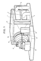
- the steam turbine 17 has an axial exhaust 18 forming part of the stator 19 (see Figure 1).
- a concrete condenser 23 is located in the extension of the exhaust 18. It comprises an enclosure 1, the bottom wall is formed by the raft 6.
- the front wall of the enclosure 1 corresponds to the connection sleeve of the turbine 17 with the condenser 23. It is in the form of a truncated pyramid.
- the side walls are provided with openings 2 to let the ends of several bundles of superimposed tubes pass. These bundles are provided with water boxes 12, 13 at each end.
- the tube bundles are located on either side of the extension of the axis of the turbine.
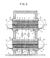
- the tubes 5 of the superposed bundles 4, 4 ′ are mounted for free expansion in vertical tubular plates 7 and in vertical tubular end plates 8.
- the bundles are located in the extension of the turbine so that the steam strikes after a medium straight stroke the bundles 4, 4 '.
- Walls of the enclosure 1 are provided below the openings 2 with steel supports 11 carrying the vertical tubular plates 7 close to the end plates 8.
- the periphery of the openings 2 is connected to the end plates 8 by a flexible seal 10 of U-shaped section.
- the water boxes 12, 13 are fixed to the end plates 8.
- Elastic pads 15 are arranged at the base of the plates 7 supported by the concrete piles 14, one of the plates 7 near one of the end plates is also provided at its base with an elastic pad 15.
- the other plate 7 is fixedly mounted on its support 11. Thanks to these elastic studs 15 the bundles 4 and 4 ′ can expand longitudinally
- 4 'of the tie rods 16 are arranged between plates 7 of the top beam 4' and the plates 7 of the bottom beam 4 to adjust the natural frequencies of the assembly.
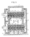
- the water boxes are made of concrete and are attached to the walls of the enclosure.
Landscapes
- Engineering & Computer Science (AREA)
- Mechanical Engineering (AREA)
- General Engineering & Computer Science (AREA)
- Chemical & Material Sciences (AREA)
- Combustion & Propulsion (AREA)
- Physics & Mathematics (AREA)
- Thermal Sciences (AREA)
- Details Of Heat-Exchange And Heat-Transfer (AREA)
Abstract
Description
- La présente invention concerne un condenseur en béton pour turbine à vapeur à échappement axial porté par un radier en béton comportant plusieurs faisceaux de tubes.
- Un tel condenseur est connu du document FR-A 2651276.
- Dans un tel condenseur les faisceaux sont montés grâce à des tirants intérieurs verticaux suspendant les faisceaux aux parois du condenseur. Mais la présence de ces tirants est très gênante pour la circulation de la vapeur.
- Le montage des faisceaux selon l'invention est fait de façon à les rendre en grande partie indépendants de l'enceinte du condenseur ce qui facilite la maintenance et en particulier le changement complet des faisceaux.
- Le condenseur selon l'invention est caractérisé en ce qu'il comporte d'une part des plaques tubulaires verticales d'extrémité reliées par des joints d'étanchéité souples aux parois du condenseur et des plaques tubulaires verticales intermédiaires, lesdites plaques étant solidarisées entre elles par des tirants et supportant à libre dilatation, les tubes des faisceaux, les plaques intermédiaires à proximité des plaques d'extrémité étant supportées par des supports internes en acier fixés sur les parois du condenseur.
- Une des plaques intermédiaires supporté par un support interne en acier est munie à sa base d'un plot élastique permettant un déplacement longitudinal. L'autre plaque est fixée sur son support interne en acier.
- Selon une réalisation préférentielle de l'invention le condenseur comporte des piles en béton internes au condenseur et portées par le radier supportant les plaques intermédiaires des faisceaux situés à proximité du radier.
- D'autre part ces plaques supportées par les piles en béton sont munies à leur base de plots élastiques permettant le déplacement longitudinal.
- Ainsi on réalise un appui et un guidage des faisceaux. Les faisceaux sont auto-porteurs et à libre dilatation.
- La présente invention sera mieux comprise à la lumière de la description qui va suivre dans laquelle:
- La figure 1 représente une turbine à échappement axial avec un condenseur en béton situé dans son prolongement.
- La figure 2 représente en coupe une première réalisation du condenseur selon l'invention.
- La figure 3 représente en coupe une deuxième réalisation du condenseur selon l'invention.
- La turbine à vapeur 17 comporte un échappement axial 18 faisant partie du stator 19 (voirfigure 1).
- Elle repose sur un radier en béton 6 par l'intermédiaire d'appuis ou d'appendices en béton 20, 21, 22. Un condenseur en béton 23 est situé dans le prolongement de l'échappement 18. Il comporte une enceinte 1 dont la paroi inférieure est constituée par le radier 6.
- La paroi avant de l'enceinte 1 correspond à la manchette de raccordement de la turbine 17 avec le condenseur 23. Elle est en forme de pyramide tronquée.
- Les parois latérales sont munies d'ouvertures 2 pour laisser passer les extrémités de plusieurs faisceaux de tubes superposés. Ces faisceaux sont munis de boites à eau 12, 13 à chaque extrémité. Les faisceaux de tubes sont situés de part et d'autre du prolongement de l'axe de la turbine.
- Dans le condenseur selon l'invention (voir figure 2) les tubes 5 des faisceaux 4, 4' superposés sont montés à libre dilatation dans des plaques verticales tubulaires 7 et dans des plaques verticales tubulaires d'extrémité 8. Les faisceaux sont situés dans le prolongement de la turbine si bien que la vapeur vient frapper après une course moyenne rectiligne les faisceaux 4, 4'.
- Les diverses plaques tubulaires 7 et 8 sont solidarisées par des tirants horizontaux 9.
- Des parois de l'enceinte 1 sont munies au-dessous des ouvertures 2 de supports en acier 11 portant les plaques tubulaires verticales 7 proches des plaques d'extrémité 8.
- Le pourtour des ouvertures 2 est relié aux plaques d'extrémité 8 par un joint d'étanchéité souple 10 de section en forme de U.
- Les boîtes à eau 12, 13 sont fixées sur les plaques d'extrémité 8.
- Pour supporter le faisceau du bas 4 on utilise en plus des piles en béton 14 internes à l'enceinte portées par le radier 6. Ces piles 14 supportent les plaques verticales 7 non supportées par les parois du condenseur.
- Des plots élastiques 15 sont disposés à la base des plaques 7 supportés par les piles en béton 14, une des plaques 7 proches d'une des plaques d'extrémités est munie également à sa base d'un plot élastique 15. L'autre plaque 7 est montée fixe sur son support 11. Grâce à ces plots élastiques 15 les faisceaux 4 et 4' peuvent se dilater longitudinalement
- Pour des faisceaux 4, 4' des tirants 16 sont disposés entre des plaques 7 du faisceau du haut 4' et les plaques 7 du faisceau du bas 4 pour régler les fréquences propres de l'ensemble.
- Selon la seconde réalisation représentée à la figure 3 les boîtes à eau sont faites en béton et sont rapportées sur les parois de l'enceinte.
- Ainsi l'eau entre dans le faisceau supérieur par la boîte avant supérieure 12' puis sort du faisceau supérieur 4' pour entrer dans le faisceau inférieur 4 à travers la boîte arrière 13 et finalement sort du faisceau inférieur 4 par la boîte avant inférieure 12".
Claims (5)
Applications Claiming Priority (2)
| Application Number | Priority Date | Filing Date | Title |
|---|---|---|---|
| FR9212581 | 1992-10-21 | ||
| FR9212581A FR2697053B1 (fr) | 1992-10-21 | 1992-10-21 | Condenseur en béton pour turbine à vapeur à échappement axial avec montage simplifié des faisceaux. |
Publications (2)
| Publication Number | Publication Date |
|---|---|
| EP0594499A1 true EP0594499A1 (fr) | 1994-04-27 |
| EP0594499B1 EP0594499B1 (fr) | 1997-01-22 |
Family
ID=9434730
Family Applications (1)
| Application Number | Title | Priority Date | Filing Date |
|---|---|---|---|
| EP93402568A Expired - Lifetime EP0594499B1 (fr) | 1992-10-21 | 1993-10-19 | Condenseur en béton pour turbine à vapeur à échappement axial avec montage simplifié des faisceaux |
Country Status (5)
| Country | Link |
|---|---|
| US (1) | US5522454A (fr) |
| EP (1) | EP0594499B1 (fr) |
| JP (1) | JPH06212908A (fr) |
| DE (1) | DE69307652T2 (fr) |
| FR (1) | FR2697053B1 (fr) |
Cited By (4)
| Publication number | Priority date | Publication date | Assignee | Title |
|---|---|---|---|---|
| DE19523923A1 (de) * | 1995-06-30 | 1997-01-02 | Abb Management Ag | Niederdruck-Dampfturbine |
| WO1998015720A1 (fr) * | 1996-10-08 | 1998-04-16 | Siemens Aktiengesellschaft | Systeme de turbine a vapeur |
| EP1126227A1 (fr) * | 2000-02-09 | 2001-08-22 | ALSTOM POWER (Schweiz) AG | Condenseur de vapeur |
| CN103742210A (zh) * | 2013-12-27 | 2014-04-23 | 陕西大唐新能电力设计有限公司 | 一种水泥生产线转动机械采用汽轮机拖动的方法 |
Families Citing this family (7)
| Publication number | Priority date | Publication date | Assignee | Title |
|---|---|---|---|---|
| US6796453B2 (en) | 2002-11-13 | 2004-09-28 | Stan A. Sanders | Cellular reservoir flexible pressure vessel, apparatus and method for making same |
| DE102006052990B4 (de) * | 2006-11-10 | 2008-11-13 | Atlas Copco Energas Gmbh | Anordnung mit einer Turbomaschine, einem Kühler und einem Tragrahmen |
| EP2085732B1 (fr) * | 2008-02-04 | 2014-04-09 | ATEC GmbH & Co. KG | Echangeur thermique en verre avec plaque tubulaire en plastique |
| CN103582743B (zh) * | 2011-03-01 | 2015-10-21 | 阿尔斯通技术有限公司 | 联合循环发电设备 |
| WO2012143751A2 (fr) * | 2011-04-21 | 2012-10-26 | Carrier Corporation | Condensateur/accumulateur et systèmes et procédés de commande |
| CN102692139A (zh) * | 2012-05-30 | 2012-09-26 | 深圳中兴新源环保股份有限公司 | 水膜蒸发凝汽器真空管箱 |
| US10156171B2 (en) | 2015-08-07 | 2018-12-18 | Cummins Emission Solutions Inc. | Mounting aftertreatment systems from service joints |
Citations (4)
| Publication number | Priority date | Publication date | Assignee | Title |
|---|---|---|---|---|
| GB121510A (en) * | 1917-12-15 | 1918-12-16 | Arthur Edwin Leigh Scanes | Improvements in or relating to Surface Condensers. |
| US1831454A (en) * | 1930-08-15 | 1931-11-10 | Ingersoll Rand Co | Condenser |
| GB1015052A (en) * | 1961-05-17 | 1965-12-31 | English Electric Co Ltd | Improvements in and relating to steam condensers |
| FR2651276A1 (fr) * | 1989-08-28 | 1991-03-01 | Alsthom Gec | Condenseur en beton pour turbine a echappement axial et turbine munie d'un tel condenseur. |
Family Cites Families (15)
| Publication number | Priority date | Publication date | Assignee | Title |
|---|---|---|---|---|
| US1536148A (en) * | 1918-11-25 | 1925-05-05 | Westinghouse Electric & Mfg Co | Condenser |
| DE492871C (de) * | 1927-03-22 | 1930-02-27 | Paul H Mueller Dr Ing | Oberflaechenkondensator mit gekruemmten, an beiden Seiten starr in den Rohrboeden befestigten Kuehlrohren |
| US1769963A (en) * | 1927-04-14 | 1930-07-08 | Griscom Russell Co | Gas-cooling apparatus |
| US1772806A (en) * | 1928-12-12 | 1930-08-12 | Worthington Pump & Mach Corp | Adjustable supporting plate for surface condensers |
| US1894279A (en) * | 1930-03-24 | 1933-01-17 | Westinghouse Electric & Mfg Co | Condenser |
| US2088931A (en) * | 1936-06-17 | 1937-08-03 | Superheater Co Ltd | Supporting means for economizers |
| US2181486A (en) * | 1938-03-19 | 1939-11-28 | Andale Co | Heat exchange equipment |
| US2237903A (en) * | 1940-01-25 | 1941-04-08 | Robert W Drake | Open type condenser |
| US2876975A (en) * | 1957-10-28 | 1959-03-10 | Aluminum Co Of America | Tube supporting means for fluidized heat exchange apparatus |
| US4183401A (en) * | 1977-09-28 | 1980-01-15 | Carrier Corporation | Combination tube sheet and baffle |
| FR2405451A1 (fr) * | 1977-10-07 | 1979-05-04 | Hamon | Echangeur de chaleur, notamment pour refrigerant atmospherique |
| US4619315A (en) * | 1985-04-10 | 1986-10-28 | Combustion Engineering, Inc. | Fluidized bed boiler in-bed tube support bracket |
| US4738310A (en) * | 1985-08-26 | 1988-04-19 | United Mcgill Corporation | Heat exchanger |
| FR2646470B1 (fr) * | 1989-04-26 | 1991-07-05 | Alsthom Gec | Systeme de supportage du rotor dans une turbine a echappement axial avec le palier cote echappement a raideur isotrope, directement flasque sur la fondation |
| FR2646469B1 (fr) * | 1989-04-28 | 1991-07-05 | Alsthom Gec | Systeme de supportage du rotor dans une turbine a echappement axial avec le palier cote echappement integre a la fondation |
-
1992
- 1992-10-21 FR FR9212581A patent/FR2697053B1/fr not_active Expired - Fee Related
-
1993
- 1993-10-19 EP EP93402568A patent/EP0594499B1/fr not_active Expired - Lifetime
- 1993-10-19 DE DE69307652T patent/DE69307652T2/de not_active Expired - Fee Related
- 1993-10-21 JP JP5263488A patent/JPH06212908A/ja active Pending
-
1995
- 1995-05-11 US US08/439,497 patent/US5522454A/en not_active Expired - Fee Related
Patent Citations (4)
| Publication number | Priority date | Publication date | Assignee | Title |
|---|---|---|---|---|
| GB121510A (en) * | 1917-12-15 | 1918-12-16 | Arthur Edwin Leigh Scanes | Improvements in or relating to Surface Condensers. |
| US1831454A (en) * | 1930-08-15 | 1931-11-10 | Ingersoll Rand Co | Condenser |
| GB1015052A (en) * | 1961-05-17 | 1965-12-31 | English Electric Co Ltd | Improvements in and relating to steam condensers |
| FR2651276A1 (fr) * | 1989-08-28 | 1991-03-01 | Alsthom Gec | Condenseur en beton pour turbine a echappement axial et turbine munie d'un tel condenseur. |
Cited By (7)
| Publication number | Priority date | Publication date | Assignee | Title |
|---|---|---|---|---|
| DE19523923A1 (de) * | 1995-06-30 | 1997-01-02 | Abb Management Ag | Niederdruck-Dampfturbine |
| US5779435A (en) * | 1995-06-30 | 1998-07-14 | Asea Brown Boveri Ag | Low-pressure steam turbine |
| DE19523923C2 (de) * | 1995-06-30 | 2003-09-18 | Alstom | Niederdruck-Dampfturbine |
| WO1998015720A1 (fr) * | 1996-10-08 | 1998-04-16 | Siemens Aktiengesellschaft | Systeme de turbine a vapeur |
| EP1126227A1 (fr) * | 2000-02-09 | 2001-08-22 | ALSTOM POWER (Schweiz) AG | Condenseur de vapeur |
| US6360543B2 (en) | 2000-02-09 | 2002-03-26 | Alstom (Schweiz) Ag | Steam condenser |
| CN103742210A (zh) * | 2013-12-27 | 2014-04-23 | 陕西大唐新能电力设计有限公司 | 一种水泥生产线转动机械采用汽轮机拖动的方法 |
Also Published As
| Publication number | Publication date |
|---|---|
| FR2697053A1 (fr) | 1994-04-22 |
| JPH06212908A (ja) | 1994-08-02 |
| EP0594499B1 (fr) | 1997-01-22 |
| DE69307652T2 (de) | 1997-05-15 |
| FR2697053B1 (fr) | 1994-12-09 |
| US5522454A (en) | 1996-06-04 |
| DE69307652D1 (de) | 1997-03-06 |
Similar Documents
| Publication | Publication Date | Title |
|---|---|---|
| EP0594499B1 (fr) | Condenseur en béton pour turbine à vapeur à échappement axial avec montage simplifié des faisceaux | |
| EP0415314A1 (fr) | Condenseur en béton pour turbine à échappement axial et turbine munie d'un tel condenseur | |
| CA1271377A (fr) | Faisceau tubulaire modulaire pour condenseur de vapeur et condenseur de vapeur en faisant application | |
| MX9301462A (es) | Calentador de agua de tubo 'u' con flama dirigida hacia abajo. | |
| EP0394899A1 (fr) | Système de supportage du rotor dans une turbine à échappement axial avec le palier côté échappement à raideur isotrope, directement flasqué sur la fondation | |
| US3884442A (en) | Two post insulator support for utility poles | |
| EP0395110B1 (fr) | Système de supportage du rotor dans une turbine à échappement axial avec le palier côté échappement intégré à la fondation | |
| CA2056135C (fr) | Element de signalisation temporaire pour voie publique ou analogue | |
| FR2737880A1 (fr) | Dispositif de guidage des gaz d'echappement et de l'air use sur des navires | |
| JP2006028899A (ja) | 鉄骨構造物の屋根受け部における柱梁継手構造 | |
| JPS61229723A (ja) | 積み換えブリツジ | |
| CA2319620A1 (fr) | Grille pour tube electronique a faisceau axial | |
| FR2763964B1 (fr) | Amelioration du flux gazeux dans un reacteur d'epitaxie | |
| EP0039870B1 (fr) | Dispositif de suspension d'une gaine de circulation de gaz | |
| FR2569668A1 (fr) | Piscine souple, a elevation autonome et rapide | |
| SU1746117A1 (ru) | Устройство дл креплени трубчатых змеевиков котла | |
| JP2894221B2 (ja) | 鋼管コンクリート柱とプレストレスト梁の仕口構造 | |
| FR2758578A1 (fr) | Dispositif pour stabiliser les pentes et les talus | |
| FR2568993A1 (fr) | Dispositif de solidarisation de troncons extremes adjacents d'un panneau de tubes horizontaux | |
| KR940007313A (ko) | 거푸집겸용 조립식 맨홀관체의 구조 | |
| RU2000124163A (ru) | Солнечный абсорбер | |
| JPH03132304A (ja) | 消波管の製造方法 | |
| CH571160A5 (en) | Construction of volume chamber for hydraulic turbine - for large scale power plants embedded in concrete uses circular cross sections | |
| FR2641848A1 (fr) | Faisceau de surchauffe pour separateur-surchauffeur de vapeur a tubes horizontaux | |
| KR200159561Y1 (ko) | 로봇 상하 이동장치 |
Legal Events
| Date | Code | Title | Description |
|---|---|---|---|
| PUAI | Public reference made under article 153(3) epc to a published international application that has entered the european phase |
Free format text: ORIGINAL CODE: 0009012 |
|
| AK | Designated contracting states |
Kind code of ref document: A1 Designated state(s): CH DE FR GB IT LI |
|
| 17P | Request for examination filed |
Effective date: 19940827 |
|
| 17Q | First examination report despatched |
Effective date: 19950926 |
|
| GRAG | Despatch of communication of intention to grant |
Free format text: ORIGINAL CODE: EPIDOS AGRA |
|
| GRAH | Despatch of communication of intention to grant a patent |
Free format text: ORIGINAL CODE: EPIDOS IGRA |
|
| GRAH | Despatch of communication of intention to grant a patent |
Free format text: ORIGINAL CODE: EPIDOS IGRA |
|
| GRAA | (expected) grant |
Free format text: ORIGINAL CODE: 0009210 |
|
| AK | Designated contracting states |
Kind code of ref document: B1 Designated state(s): CH DE FR GB IT LI |
|
| ITF | It: translation for a ep patent filed | ||
| REG | Reference to a national code |
Ref country code: CH Ref legal event code: NV Representative=s name: GEC ALSTHOM (SUISSE) S.A. DEPARTEMENT DES BREVETS Ref country code: CH Ref legal event code: EP |
|
| REF | Corresponds to: |
Ref document number: 69307652 Country of ref document: DE Date of ref document: 19970306 |
|
| GBT | Gb: translation of ep patent filed (gb section 77(6)(a)/1977) |
Effective date: 19970307 |
|
| PLBE | No opposition filed within time limit |
Free format text: ORIGINAL CODE: 0009261 |
|
| STAA | Information on the status of an ep patent application or granted ep patent |
Free format text: STATUS: NO OPPOSITION FILED WITHIN TIME LIMIT |
|
| 26N | No opposition filed | ||
| PGFP | Annual fee paid to national office [announced via postgrant information from national office to epo] |
Ref country code: FR Payment date: 19980923 Year of fee payment: 6 Ref country code: GB Payment date: 19980923 Year of fee payment: 6 |
|
| PGFP | Annual fee paid to national office [announced via postgrant information from national office to epo] |
Ref country code: DE Payment date: 19980928 Year of fee payment: 6 |
|
| PGFP | Annual fee paid to national office [announced via postgrant information from national office to epo] |
Ref country code: CH Payment date: 19981014 Year of fee payment: 6 |
|
| PG25 | Lapsed in a contracting state [announced via postgrant information from national office to epo] |
Ref country code: GB Free format text: LAPSE BECAUSE OF NON-PAYMENT OF DUE FEES Effective date: 19991019 |
|
| PG25 | Lapsed in a contracting state [announced via postgrant information from national office to epo] |
Ref country code: LI Free format text: LAPSE BECAUSE OF NON-PAYMENT OF DUE FEES Effective date: 19991031 Ref country code: CH Free format text: LAPSE BECAUSE OF NON-PAYMENT OF DUE FEES Effective date: 19991031 |
|
| GBPC | Gb: european patent ceased through non-payment of renewal fee |
Effective date: 19991019 |
|
| REG | Reference to a national code |
Ref country code: CH Ref legal event code: PL |
|
| PG25 | Lapsed in a contracting state [announced via postgrant information from national office to epo] |
Ref country code: FR Free format text: LAPSE BECAUSE OF NON-PAYMENT OF DUE FEES Effective date: 20000630 |
|
| PG25 | Lapsed in a contracting state [announced via postgrant information from national office to epo] |
Ref country code: DE Free format text: LAPSE BECAUSE OF NON-PAYMENT OF DUE FEES Effective date: 20000801 |
|
| REG | Reference to a national code |
Ref country code: FR Ref legal event code: ST |
|
| PG25 | Lapsed in a contracting state [announced via postgrant information from national office to epo] |
Ref country code: IT Free format text: LAPSE BECAUSE OF NON-PAYMENT OF DUE FEES;WARNING: LAPSES OF ITALIAN PATENTS WITH EFFECTIVE DATE BEFORE 2007 MAY HAVE OCCURRED AT ANY TIME BEFORE 2007. THE CORRECT EFFECTIVE DATE MAY BE DIFFERENT FROM THE ONE RECORDED. Effective date: 20051019 |