EP1127719A2 - Système avertisseur de pression insuffisante destiné aux pneumatiques - Google Patents
Système avertisseur de pression insuffisante destiné aux pneumatiques Download PDFInfo
- Publication number
- EP1127719A2 EP1127719A2 EP01103769A EP01103769A EP1127719A2 EP 1127719 A2 EP1127719 A2 EP 1127719A2 EP 01103769 A EP01103769 A EP 01103769A EP 01103769 A EP01103769 A EP 01103769A EP 1127719 A2 EP1127719 A2 EP 1127719A2
- Authority
- EP
- European Patent Office
- Prior art keywords
- tire
- whistle
- bladder
- rim
- tire assembly
- Prior art date
- Legal status (The legal status is an assumption and is not a legal conclusion. Google has not performed a legal analysis and makes no representation as to the accuracy of the status listed.)
- Withdrawn
Links
- 230000007246 mechanism Effects 0.000 claims description 12
- 230000007613 environmental effect Effects 0.000 claims description 9
- 238000009527 percussion Methods 0.000 claims description 4
- 239000000463 material Substances 0.000 description 7
- 230000000284 resting effect Effects 0.000 description 7
- 239000002184 metal Substances 0.000 description 6
- 230000010349 pulsation Effects 0.000 description 6
- 239000011324 bead Substances 0.000 description 5
- 238000010276 construction Methods 0.000 description 2
- 230000007797 corrosion Effects 0.000 description 2
- 238000005260 corrosion Methods 0.000 description 2
- 238000000034 method Methods 0.000 description 2
- 230000004044 response Effects 0.000 description 2
- 230000000007 visual effect Effects 0.000 description 2
- 229910000831 Steel Inorganic materials 0.000 description 1
- 230000004075 alteration Effects 0.000 description 1
- 230000008859 change Effects 0.000 description 1
- 239000002131 composite material Substances 0.000 description 1
- 230000006835 compression Effects 0.000 description 1
- 238000007906 compression Methods 0.000 description 1
- 230000005611 electricity Effects 0.000 description 1
- 238000005516 engineering process Methods 0.000 description 1
- 239000000945 filler Substances 0.000 description 1
- 238000001914 filtration Methods 0.000 description 1
- 239000000446 fuel Substances 0.000 description 1
- 230000004048 modification Effects 0.000 description 1
- 238000012986 modification Methods 0.000 description 1
- 208000001491 myopia Diseases 0.000 description 1
- 239000004033 plastic Substances 0.000 description 1
- 230000008569 process Effects 0.000 description 1
- 230000002035 prolonged effect Effects 0.000 description 1
- 230000008439 repair process Effects 0.000 description 1
- 230000003252 repetitive effect Effects 0.000 description 1
- 238000005096 rolling process Methods 0.000 description 1
- 239000007787 solid Substances 0.000 description 1
- 239000010959 steel Substances 0.000 description 1
Images



Classifications
-
- B—PERFORMING OPERATIONS; TRANSPORTING
- B60—VEHICLES IN GENERAL
- B60C—VEHICLE TYRES; TYRE INFLATION; TYRE CHANGING; CONNECTING VALVES TO INFLATABLE ELASTIC BODIES IN GENERAL; DEVICES OR ARRANGEMENTS RELATED TO TYRES
- B60C23/00—Devices for measuring, signalling, controlling, or distributing tyre pressure or temperature, specially adapted for mounting on vehicles; Arrangement of tyre inflating devices on vehicles, e.g. of pumps or of tanks; Tyre cooling arrangements
- B60C23/06—Signalling devices actuated by deformation of the tyre, e.g. tyre mounted deformation sensors or indirect determination of tyre deformation based on wheel speed, wheel-centre to ground distance or inclination of wheel axle
- B60C23/063—Generating directly an audible signal by deformation of the tyre
-
- B—PERFORMING OPERATIONS; TRANSPORTING
- B60—VEHICLES IN GENERAL
- B60C—VEHICLE TYRES; TYRE INFLATION; TYRE CHANGING; CONNECTING VALVES TO INFLATABLE ELASTIC BODIES IN GENERAL; DEVICES OR ARRANGEMENTS RELATED TO TYRES
- B60C19/00—Tyre parts or constructions not otherwise provided for
-
- B—PERFORMING OPERATIONS; TRANSPORTING
- B60—VEHICLES IN GENERAL
- B60C—VEHICLE TYRES; TYRE INFLATION; TYRE CHANGING; CONNECTING VALVES TO INFLATABLE ELASTIC BODIES IN GENERAL; DEVICES OR ARRANGEMENTS RELATED TO TYRES
- B60C19/00—Tyre parts or constructions not otherwise provided for
- B60C2019/006—Warning devices, e.g. devices generating noise due to flat or worn tyres
Definitions
- the present invention relates to a low pressure warning system for a pneumatic tire, and more particularly for a runflat tire.
- Loss of tire pressure can result from a variety of causes such as a deteriorated seal between the tire and rim or a tire puncture by a sharp object.
- Various methods have been devised for enabling the safe continued operation of deflated or under-inflated (flat) tires without damaging the tire further and without compromising vehicle handling while driving to where the tire can be changed.
- Tires designed for continued operation under deflated or under-inflated conditions are referred to as "extended mobility technology" tires or “EMT” tires. They are also called “runflat” tires, since they are capable of being driven when flat.
- the runflat tire's structure alone has sufficient strength to support the vehicle load when the tire is deflated.
- US-A- 4,111,249 discloses a runflat tire having an annular compression band (hoop) of solid high-strength metal or reinforced composite, located below the tread, either under or within the carcass.
- US-A-4,059,138 discloses a runflat tire having, around the metal hub, an elastomeric ring that supports the inner central portion of the carcass when the tire is deflated.
- inserts are fillers generally having a crescent shaped cross-section, located within the sidewall, which is the region in the tire experiencing the greatest flex under load.
- the inserts reinforce (stiffen) the sidewall to avoid sidewall buckling during runflat operation (i.e. while running under-inflated).
- a conventional (non-runflat) tire's sidewalls and tread continually buckle and flop as they rotate when driven while flat, so the driver can usually sense the existence of the flat through the resulting sounds he hears and the vibrations he feels.
- a runflat tire's sidewalls and tread do not collapse or buckle, unless they have been driven in runflat operation to the point of failure. Runflat inserts often operate so smoothly that the driver is unaware of a tire deflation and can continue to drive until the insert eventually fails.
- tire deflation indicators (or alarms) have been disclosed in the patent literature, although few of them particularly for a runflat tire. Many tire deflation indicators include a pressure sensor and radio frequency transmitter within the tire cavity and a receiver outside the tire cavity. These designs have the disadvantage of high cost and difficulty of conveying electric power to the components in the tire cavity. Other tire deflation indicators entail sensing the difference in rotational speeds between the vehicle's four tires. They are costly to implement and suffer from interferences. Other tire deflation indicators include an electronic pressure sensor attached to a valve stem or tube leading to the tire cavity. These have the difficulty of conveying electric power to the rotating components. Other tire deflation indicators include a mechanical pressure responsive mechanism attached to a valve stem or tube exiting the rim. These add complexity to the rim construction. Other tire deflation indicators have a "feeler" rod, connected to a switch, that activates the switch when it contacts the bulging tire sidewall or the road surface. These mechanisms are cumbersome and prone to breakage.
- tire deflation indicators are disposed within the tire cavity and do not require electric power.
- some tire deflation indicators have an insert (either in the sidewall or tire cavity) having nonuniform radius to cause wheel vibration in runflat operation to alert the driver.
- These designs can be costly and yield an uncomfortable runflat ride.
- US-A- 3,154,048 discloses a tire deflection warning device positioned within the tire's interior, having a metal knocker and a spring, both positioned between a wheel rim and belt around the rim. When the tire flexes inwardly, the knocker is brought suddenly against the steel rim with each tire rotation to create a loud noise.
- US-A- 4,476,455 discloses an inflation warning device in which a ball strikes the wall of a case upon each revolution when the tire is deflated.
- US-A- 4,487,154 and 4,201,147 disclose low pressure warning devices having a striker or hammer that strikes the wheel rim when the pressure is low.
- Other low tire pressure alarms are disclosed in US-A- 3,030,911; 4,353,322; 4,580,519; and 5,207,173. These designs are prohibitively costly, can degrade wheel balance, and have rotating metal junctions that can corrode or seize. Some of them depend on centrifugal force to work, which renders them inoperative at slow speeds.
- US-A- 1,195,883 discloses a "leak-alarm for pneumatic tires” having a whistle fitted to a rubber bulb that is vulcanized to, or made an integral part of, an inner tube. When the inner tube is deflated, the bulb is "compressed, forcing the air from the bulb through the whistle and sounding the alarm". This has the disadvantages of requiring a specially-made inner tube and causing tire imbalance. Even if the device is applied to a tubeless tire (which is not disclosed), it would require a specially-made tire and cause tire imbalance.
- US-A- 3,489,998; 3,659,264; 4,067,376 and 4,103,282 disclose various tire pressure warning systems entailing components mounted to vehicle wheel that, in response to low inflation, produce an acoustic (sonic or ultrasonic) vibration that is sensed by a receiver outside the tire, to generate a warning signal to the driver. These systems are not responsive to tread deflection.
- tread deflection alarm that is responsive to tread deflection so that it warns of heavy vehicle load along with low pressure. It is desirable to have a tread deflection alarm that is simple, low cost, light, not affecting tire balance, adaptable to standard tires and rims without alteration, out-of-sight (concealed within the tire), and not requiring electric power.
- a tire assembly comprises a tire (such as a runflat tire), a rim having a rim well ; and an alarm system.
- the tire assembly is characterized by the alarm system having a belt disposed tightly around the rim well and a first bladder attached to the belt.
- the alarm system can include a first whistle attached to the first bladder disposed within the tire cavity.
- the alarm system can have a second bladder with a second whistle attached to the belt on the opposite side of the rim well from the first bladder.
- the alarm system can have a counterweight attached to the belt on the opposite side of the rim well from the first bladder.
- Both the first and second whistles emit an audible whistle when air passes through them in either the inhale and/or exhale directions.
- the whistles can also emit an ultrasonic whistle at a distinct frequency; and the tire assembly also has, disposed outside the tire cavity, an electronic circuit that is sensitive to the distinct ultrasonic frequency and can distinguish the whistle of the whistle from environmental noise.
- the circuit can distinguish the whistle sound from environmental noise based on frequency and periodicity.
- the first bladder is connected to a percussion noise-making mechanism within the tire cavity.
- cross-sectional views presented herein may be in the form "near-sighted" cross-sectional views, omitting certain background lines that would otherwise be visible in a true cross-sectional view.
- FIGURE 1A is a partial perspective cutaway view of a tire assembly 100 according to the first embodiment of the present invention, as it would be when it is partially-deflated and resting on a road surface (or "ground") 104.
- the tire assembly 100 has a tire 110, a rim 112 and a tire deflection alarm system (“alarm system”) 114.
- the tire 110 has a tread area 116 (meant herein to include the tread and materials directly beneath the tread such as belts, plies and innerliner), two sidewalls 118 and two bead regions 120.
- the portion of the tread area 116 that contacts the ground 104 is called a footprint area 122.
- the rim 112 has a rim well 124 and two rim flanges 126 upon which the bead regions 120 are seated snuggly to form an airtight seal.
- a tire cavity 128 is bounded by the rim well 124 and inner surfaces of the tire 110.
- the alarm system 114 has a belt 130 disposed tightly around the rim well 124, a first bladder (or just “bladder”) 132a (having a first bladder opening 134a or just “bladder opening”, i.e. inlet) attached to the belt 130, a “first whistle” 136a (or just “whistle”) affixed to the first bladder opening 134a, and a counterweight 138 attached to the belt 130 on the opposite side of the rim 124 from the first bladder 132a and the first whistle 136a.
- the bladder 132a is constructed so that, when squeezed (under external force), air from within the bladder is blown through its opening 134a and out through the whistle 136a, and when the force is removed, the bladder automatically expands to self-inflate with air passing back through the alarm 136a.
- the bladder 132a can equally be in the form of a bellows that is spring-loaded to bias it open.
- the whistle 136a is any air activated noise maker or alarm, emitting a loud audible sound (i.e. "whistle") when air passes through it preferably whether in the inhale or exhale direction ("inhale” meaning toward the bladder 132a and "exhale” meaning away from the bladder). However, it is within the scope of the present invention for the whistle 136a to whistle upon only inhale or only exhale of air.
- the bladder 132a and the whistle 136a are preferably made of plastic to be low cost, light weight and corrosion resistant.
- the counterweight 138 is any mass of material that balances out the weight of the bladder 132a and the whistle 136a, to keep the alarm system 114, and hence the tire assembly 100, balanced.
- the counterweight 138 can be any suitable shape or size and of any suitable material.
- the belt can be constructed of any suitable design and material.
- US-A- 4,235,184 discloses a device for mounting a sensor on a tire rim, having metal strapping, a strapping seal and counterweight components.
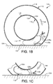
- FIGURE 1B is a cross-sectional side view, cut along the equatorial plane (plane perpendicular to the tire axis and passing through center of the tread), of the partially-deflated tire assembly 100 of FIGURE 1A, wherein the tire assembly is rotating and the bladder 132a is approaching the ground 104.
- FIGURE 1C is a cross-sectional side view, cut along the equatorial plane, of the partially-deflated tire assembly 100 of FIGURE 1B, wherein the tire assembly has rotated further and the bladder 132a is moving away from the ground 104.
- the reference numerals in FIGURES 1B and 1C match those of FIGURE 1A.
- the bladder 132a is not adjacent to the footprint area 122, it is self-inflated.
- FIGURE 1B as the tire assembly 100 rotates (as illustrated by arrow 140), bringing the bladder 132a adjacent to the footprint area 122, the bladder 132a is squeezed between the rim well 124 and the footprint area 122, causing the bladder to exhale air out its opening 134a and through the whistle 136a (as illustrated by arrows 142), causing it to whistle.
- the bladder 132a whistles twice per tire revolution, powered from repetitive pneumatic pulsations (inhale and exhale) from the bladder 132a as the tire assembly 100 rotates.
- the exhaled whistle and the inhaled whistle being in rapid succession, may be perceived as one whistle per revolution. If the whistle 136a is the type that only whistles upon exhale or only upon inhale, then it will whistle only once per tire revolution. The audible whistles alert the driver to the deflated condition.
- the alarm assembly 114 is designed such that, when the tire 110 is inflated above some threshold inflation, the bladder 132a is not squeezed between the footprint area 122 and the rim 112, or at least not squeezed enough to produce an audible whistle.
- the bladder size is selected such that, below the threshold inflation (typically 1 bar), the alarm system 114' will whistle with each revolution, and above the threshold inflation, it will not whistle.
- FIGURE 1D is a cross-sectional side view of a tire assembly 100' of a second embodiment of the present invention, as it would be when partially-deflated and resting on a road surface 104.
- the tire assembly 100' is identical to the tire assembly 100 of the first embodiment of FIGURES 1A-1C, except that the tire assembly 100' has an alarm system 114' that has, in place of the counterweight (140 in FIGURES 1A-1C), a second bladder 132b (having a second opening 134b) and a second whistle 136b.
- the reference numbers in FIGURE 1D correspond to those in FIGURES 1A-1C.
- the alarm system 114' of the second embodiment works in the same way as the alarm system 114 of the first embodiment, except that, by having two whistles 136a,136b, it whistles twice as many times per tire revolution. Whereas, in the first embodiment, the first bladder 132a and first whistle 136a are counterbalanced by the weight 138, in the second embodiment, the first bladder 132a and first whistle 136a are counterbalanced by the second bladder 132b and the second whistle 136b.
- FIGURE 2 is a partially-diagrammatic and partially cross-sectional (cut along the equitorial plane) side view of a tire assembly 200 according to a third embodiment of the present invention.
- the pneumatic pulsations when the tire is deflated
- the whistle is ultrasonic (typically inaudible) and is sensed by an electronic circuit disposed outside the tire cavity, which then informs the driver of the deflated condition via an audible alarm or visual display inside the vehicle.
- the tire assembly 200 mounted on a vehicle (not shown), has a tire 210 (identical to the tire 110 of FIGURES 1A-1D), a rim 212 (identical the rim 112 of FIGURES 1A-1D) and a tire deflection alarm system ("alarm system") 214.
- the tire 210 includes a tread area 216, two sidewalls (not shown) and two bead regions (not shown). The portion of the tread area 216 that contacts the ground 204 is called a footprint area 222.
- the rim 212 includes a rim well 224 and two rim flanges (not shown) upon which the bead regions are seated snuggly to form an airtight seal.
- a tire cavity 228 is bounded by the rim well 224 and inner surfaces of the tire 210.
- the alarm system 214 has a belt 230 disposed tightly around the rim well 224, a bladder 232 (having a bladder opening 234) attached to the belt 230, a whistle 236 connected to the bladder opening 234, and a counterweight attached to the belt 230 on the opposite side of the rim well 224 as the bladder 232 and the whistle 236.
- the whistle 236 whistles at a distinct preselected ultrasonic frequency each time air is exhaled (or alternatively inhaled, or both) by the bladder 232.
- the alarm system 214 also has, disposed outside the tire cavity 228, an electronic circuit 250 that can sense the ultrasonic whistle of the whistle 236 via a microphone 252 (or any suitable means of sensing the ultrasonic whistle) disposed outside and near the tire 210 and has filtering capability to distinguish the distinct ultrasonic whistle from environmental noise, and an audible alarm 254 inside the vehicle to inform the driver of a deflated condition.
- an electronic circuit 250 that can sense the ultrasonic whistle of the whistle 236 via a microphone 252 (or any suitable means of sensing the ultrasonic whistle) disposed outside and near the tire 210 and has filtering capability to distinguish the distinct ultrasonic whistle from environmental noise, and an audible alarm 254 inside the vehicle to inform the driver of a deflated condition.
- the alarm system 214 In operation, when the tire assembly 200 of FIGURE 2 is deflated, as the tire assembly 200 rotates, the alarm system 214 emits one distinct ultrasonic whistle per tire revolution by the same mechanism as the alarm 114 emitted audible whistles in the first embodiment.
- the ultrasonic whistles are picked up by the microphone 252 and processed by the circuitry 250, distinguishing the whistles from other, environmental, noise by their distinct frequency and their periodicity (time between whistles).
- the circuitry 250 alerts the driver of the deflated condition by means of the audible alarm 254 or visual display inside the vehicle.
- the circuitry 250 can distinguish the whistles emitted by the whistle 236 from environmental noise of the same frequency through several means. For example, if the circuitry 250 senses whistles of the correct frequency (i.e. the distinct frequency of the whistle 236) whose period is shorter than 0.01 second, the circuit can conclude that those whistles are too frequent to be emanating from the tire assembly 200 (and must be environmental noise). Additionally, if the period of the sensed whistles change significantly from one whistle to the next, the circuit can conclude that it is changing too quickly to be emanating from the tire assembly 200 (and must be environmental noise). To even more precisely distinguish the whistles from environmental noise, the circuit 252 can be connected to (and communicate with) the vehicle's speedometer to check whether the periodicity of the sensed whistle is reasonable in light of the vehicle speed.
- the correct frequency i.e. the distinct frequency of the whistle 2366
- the size of the bladder 232 is designed such that, when the tire is inflated beyond a preselected threshold (such as 1 bar), the footprint 222 is too far from the rim well 224 to squeeze the bladder 232 to produce a whistle.
- a preselected threshold such as 1 bar
- the alarm systems of the present invention are suited for non-runflat tires, they are most advantageous for runflat tires, whose deflated condition is not as easily sensed by the driver.
- the tire deflation alarm systems of the present invention have the following advantages relative to the prior art: They are relatively light, low cost, corrosion resistant, balanced around the rim, can work with any standard rim and tire, do not require a specially-modified rim or tire, do not require conveying electric power into the tire cavity, and work even at low speeds (because their mechanism is not based on centrifugal force).
- FIGURE 3 is an embodiment of the present invention, as it would be when partially-deflated and resting on a road surface (ground) 304.
- the fourth embodiment is identical to the first embodiment (FIGURE 1A-1C), except that the whistle (132a in FIGURES 1A-1C) is replaced by a percussion noise maker like a gong mechanism.
- the tire assembly 300 has a tire 310 and a rim 312 (having a rim well 324) identical to the tire 110,210 and the rim 112,212 of the three previous embodiments.
- the tire assembly 300 also has an alarm system 314 within a tire cavity 328 bounded by the rim well 324 and the inside surfaces of the tire 310.
- the alarm system 314 has a belt 330 disposed tightly around the rim well 324, a bladder 332 (identical in placement and function as the bladders 132a,132b,232 of the previous three embodiments), and a gong mechanism 360.
- the gong mechanism 360 is connected to an opening 334 of the bladder 332 by a tube 362.
- the gong mechanism 360 has a bellows 364 (affixed to either the bladder 332, the belt 330 or the rim well 324 by means any suitable means, not shown), a hammer 366 (or “clapper”) and a metal block 368 affixed to the rim 312.
- Air exiting the bladder 332 when the tire is deflated (in the process described in the first embodiment), passes through the tube 362 and inflates the bellows 364 to push the hammer 366 to strike the block 368 which vibrates the rim 312 to produce repeated clang sounds (one clang per tire revolution) to alert the driver of a flat tire.
- the pneumatic pulsations can be used to activate other mechanisms, either electronic or mechanical.
- an electric buzzer inside the tire cavity 128 can be activated by an air flow switch that conducts electricity in response to air flow.
Landscapes
- Engineering & Computer Science (AREA)
- Mechanical Engineering (AREA)
- Measuring Fluid Pressure (AREA)
Applications Claiming Priority (2)
| Application Number | Priority Date | Filing Date | Title |
|---|---|---|---|
| US09/515,076 US6367528B1 (en) | 2000-02-28 | 2000-02-28 | Tire deflection alarm |
| US515076 | 2000-02-28 |
Publications (2)
| Publication Number | Publication Date |
|---|---|
| EP1127719A2 true EP1127719A2 (fr) | 2001-08-29 |
| EP1127719A3 EP1127719A3 (fr) | 2003-11-26 |
Family
ID=24049869
Family Applications (1)
| Application Number | Title | Priority Date | Filing Date |
|---|---|---|---|
| EP01103769A Withdrawn EP1127719A3 (fr) | 2000-02-28 | 2001-02-15 | Système avertisseur de pression insuffisante destiné aux pneumatiques |
Country Status (2)
| Country | Link |
|---|---|
| US (1) | US6367528B1 (fr) |
| EP (1) | EP1127719A3 (fr) |
Families Citing this family (6)
| Publication number | Priority date | Publication date | Assignee | Title |
|---|---|---|---|---|
| US8266465B2 (en) | 2000-07-26 | 2012-09-11 | Bridgestone Americas Tire Operation, LLC | System for conserving battery life in a battery operated device |
| US7161476B2 (en) | 2000-07-26 | 2007-01-09 | Bridgestone Firestone North American Tire, Llc | Electronic tire management system |
| US20040263324A1 (en) * | 2003-06-24 | 2004-12-30 | Sanchez Ramon A. | Tire pressure sensor body and installation method |
| US7314072B2 (en) * | 2004-07-28 | 2008-01-01 | Grant Bunker | Integral pressure regulation system for tires and other vessels containing compressible fluids |
| FR2990897B1 (fr) * | 2012-05-24 | 2014-05-09 | Michelin & Cie | Pneumatique pliable, procede, utilisation |
| US12194786B2 (en) * | 2022-09-13 | 2025-01-14 | Adam Awad | Flat tire airbag system |
Citations (10)
| Publication number | Priority date | Publication date | Assignee | Title |
|---|---|---|---|---|
| US3030911A (en) | 1961-01-05 | 1962-04-24 | Dilts Fred | Vehicle tire low pressure warning device |
| US3154048A (en) | 1964-03-12 | 1964-10-27 | Wallace I Neu | Vehicle tire deflection warning device |
| US4059138A (en) | 1972-08-11 | 1977-11-22 | Uniroyal, S.A. | Run-flat tire and hub therefor |
| US4111249A (en) | 1976-11-08 | 1978-09-05 | Grumman Aerospace Corporation | Band reinforced radial tire |
| US4201147A (en) | 1977-12-26 | 1980-05-06 | Bridgestone Tire Company Limited | Tire pressure drop warning apparatus |
| US4353322A (en) | 1979-07-23 | 1982-10-12 | Rockcor, Inc. | Low inflation warning device for pneumatic tires |
| US4476455A (en) | 1980-12-26 | 1984-10-09 | Sumitomo Rubber Industries, Ltd. | Tire deflation warning device |
| US4487154A (en) | 1982-10-15 | 1984-12-11 | Rockcor, Inc. | Pressure-activated low pressure warning device |
| US4580519A (en) | 1980-10-29 | 1986-04-08 | Brewer Howell K | Low tire pressure warning device |
| US5207173A (en) | 1992-10-27 | 1993-05-04 | Sadri Frederick F | Low pressure tire alarm indicator |
Family Cites Families (29)
| Publication number | Priority date | Publication date | Assignee | Title |
|---|---|---|---|---|
| US1195883A (en) * | 1916-08-22 | George w | ||
| US1038433A (en) | 1912-01-27 | 1912-09-10 | Joseph B Polo | Tire-alarm. |
| US1144239A (en) | 1915-02-23 | 1915-06-22 | Reinforced Inner Tube Company | Inner tube for pneumatic tires. |
| US1364300A (en) | 1919-05-03 | 1921-01-04 | Parr James Edmund | Tire-alarm |
| US1445043A (en) | 1920-06-22 | 1923-02-13 | Willis G Sampson | Pneumatic-tire pressure gauge and signal |
| US1488861A (en) | 1922-10-05 | 1924-04-01 | Brown Harold | Alarm device |
| FR670363A (fr) * | 1929-02-27 | 1929-11-28 | Dispositif avertisseur de dégonflement pour pneumatiques | |
| US2713372A (en) | 1950-04-20 | 1955-07-19 | Firestone Tire & Rubber Co | Tubeless tire and safety diaphragm combination |
| US2884983A (en) | 1952-09-06 | 1959-05-05 | Cuesta Francisco Gonzalez | Safety pneumatic tire wheel |
| US2754876A (en) | 1953-05-05 | 1956-07-17 | Firestone Tire & Rubber Co | Safety tire |
| US2723700A (en) | 1954-03-18 | 1955-11-15 | Caldwell William Addison | Relief valve and pressure signal for pneumatic tires |
| US3085615A (en) | 1960-04-04 | 1963-04-16 | Goodyear Tire & Rubber | Flat tire warning device |
| US3111930A (en) | 1960-04-04 | 1963-11-26 | Walter J Zipper | Tire pressure indicator |
| US3055998A (en) | 1960-05-10 | 1962-09-25 | Jerry L Collins | Tire deflation indicator |
| FR1378047A (fr) | 1963-06-04 | 1964-11-13 | Michelin & Cie | Perfectionnements aux enveloppes de pneumatiques |
| US3489998A (en) | 1965-06-25 | 1970-01-13 | James C O Neal | Pressure warning apparatus for a pneumatic tire |
| US3413598A (en) | 1966-03-21 | 1968-11-26 | Joseph H. Uphoff | Low tire pressure warning system |
| US3533063A (en) | 1966-12-09 | 1970-10-06 | George E Garcia | Low pressure pneumatic tire transmitter |
| US3472197A (en) | 1968-01-25 | 1969-10-14 | Ford Motor Co | Low tire pressure warning device |
| US3496903A (en) | 1968-03-22 | 1970-02-24 | Ford Motor Co | Low tire pressure warning device |
| US3659264A (en) | 1970-07-20 | 1972-04-25 | Safety Res & Eng | Tire pressure alarm system |
| US3719159A (en) | 1971-12-30 | 1973-03-06 | Gen Tire & Rubber Co | Fluid pressure condition warning device |
| US3934223A (en) | 1973-12-04 | 1976-01-20 | Safety Research & Engineering Corporation | Tire pressure warning system |
| US3835808A (en) | 1973-12-18 | 1974-09-17 | Raymond Lee Organization Inc | Low pressure warning system for a tire |
| US4103282A (en) | 1975-11-03 | 1978-07-25 | Safety Research & Engineering Corporation | Acoustical tire pressure valve |
| US4235184A (en) | 1979-03-23 | 1980-11-25 | Sharon Steel Corporation | Strapping, seal and counterweight device for mounting tire pressure warning system sensors on tire rims |
| US4262724A (en) | 1979-05-03 | 1981-04-21 | Uniroyal, Inc. | Low pressure and run-flat warning system for a pneumatic tire |
| US4814744A (en) | 1987-12-01 | 1989-03-21 | Collins Design Company, Inc. | Low tire-pressure warning system |
| JPH02182507A (ja) * | 1989-01-05 | 1990-07-17 | Sumitomo Rubber Ind Ltd | ラジアルタイヤとリムの組立体 |
-
2000
- 2000-02-28 US US09/515,076 patent/US6367528B1/en not_active Expired - Fee Related
-
2001
- 2001-02-15 EP EP01103769A patent/EP1127719A3/fr not_active Withdrawn
Patent Citations (10)
| Publication number | Priority date | Publication date | Assignee | Title |
|---|---|---|---|---|
| US3030911A (en) | 1961-01-05 | 1962-04-24 | Dilts Fred | Vehicle tire low pressure warning device |
| US3154048A (en) | 1964-03-12 | 1964-10-27 | Wallace I Neu | Vehicle tire deflection warning device |
| US4059138A (en) | 1972-08-11 | 1977-11-22 | Uniroyal, S.A. | Run-flat tire and hub therefor |
| US4111249A (en) | 1976-11-08 | 1978-09-05 | Grumman Aerospace Corporation | Band reinforced radial tire |
| US4201147A (en) | 1977-12-26 | 1980-05-06 | Bridgestone Tire Company Limited | Tire pressure drop warning apparatus |
| US4353322A (en) | 1979-07-23 | 1982-10-12 | Rockcor, Inc. | Low inflation warning device for pneumatic tires |
| US4580519A (en) | 1980-10-29 | 1986-04-08 | Brewer Howell K | Low tire pressure warning device |
| US4476455A (en) | 1980-12-26 | 1984-10-09 | Sumitomo Rubber Industries, Ltd. | Tire deflation warning device |
| US4487154A (en) | 1982-10-15 | 1984-12-11 | Rockcor, Inc. | Pressure-activated low pressure warning device |
| US5207173A (en) | 1992-10-27 | 1993-05-04 | Sadri Frederick F | Low pressure tire alarm indicator |
Also Published As
| Publication number | Publication date |
|---|---|
| EP1127719A3 (fr) | 2003-11-26 |
| US6367528B1 (en) | 2002-04-09 |
Similar Documents
| Publication | Publication Date | Title |
|---|---|---|
| US6252498B1 (en) | Tire pressure detecting system for a vehicle | |
| US4476455A (en) | Tire deflation warning device | |
| US7116218B2 (en) | Vehicle-tire-state detection/communication apparatus and tire-data communication apparatus | |
| US5289161A (en) | Tire pressure indicator | |
| GB1603226A (en) | Tyre condition sensing apparatus | |
| US7271709B2 (en) | Robust method and system for the automatic detection of a detached remote tire pressure sensor of a tire pressure monitoring system | |
| US6367528B1 (en) | Tire deflection alarm | |
| JP2003267006A (ja) | 自動車輌タイヤのタイヤ圧検出装置 | |
| US3719159A (en) | Fluid pressure condition warning device | |
| US6829926B2 (en) | System for checking the air pressure in the tires of a motor vehicle | |
| US4103282A (en) | Acoustical tire pressure valve | |
| CN208053006U (zh) | 一种具有刺穿报警功能的轮胎 | |
| EP1181162B1 (fr) | Systeme permettant de verifier la pression de l'air dans les pneumatiques d'un vehicule a moteur | |
| US4814744A (en) | Low tire-pressure warning system | |
| US3993114A (en) | Pneumatic tire | |
| US6837104B2 (en) | Tire safety system | |
| US4487154A (en) | Pressure-activated low pressure warning device | |
| JPH07228111A (ja) | 自動車用タイヤ | |
| US20050051249A1 (en) | Run-flat tire | |
| US2469300A (en) | Tire | |
| EP4574469A1 (fr) | Dispositif antivol pour une roue de véhicule | |
| JPH0565004A (ja) | 中子車輪を内装した安全タイヤ及びランフラツト警告 方法 | |
| JP2005007928A (ja) | サポートリング、該サポートリングを用いたタイヤ組立体及び車両 | |
| US1359098A (en) | Deflation-alarm for pneumatic-tired wheels | |
| JPH06297922A (ja) | 空気入りタイヤ組立体および空気入りタイヤ用中子組立体 |
Legal Events
| Date | Code | Title | Description |
|---|---|---|---|
| PUAI | Public reference made under article 153(3) epc to a published international application that has entered the european phase |
Free format text: ORIGINAL CODE: 0009012 |
|
| AK | Designated contracting states |
Kind code of ref document: A2 Designated state(s): AT BE CH CY DE DK ES FI FR GB GR IE IT LI LU MC NL PT SE TR |
|
| AX | Request for extension of the european patent |
Free format text: AL;LT;LV;MK;RO;SI |
|
| PUAL | Search report despatched |
Free format text: ORIGINAL CODE: 0009013 |
|
| AK | Designated contracting states |
Kind code of ref document: A3 Designated state(s): AT BE CH CY DE DK ES FI FR GB GR IE IT LI LU MC NL PT SE TR |
|
| AX | Request for extension of the european patent |
Extension state: AL LT LV MK RO SI |
|
| RIC1 | Information provided on ipc code assigned before grant |
Ipc: 7B 60C 23/06 B Ipc: 7B 60C 23/04 B Ipc: 7B 60C 17/00 A |
|
| 17P | Request for examination filed |
Effective date: 20040526 |
|
| AKX | Designation fees paid |
Designated state(s): DE FR GB |
|
| STAA | Information on the status of an ep patent application or granted ep patent |
Free format text: STATUS: THE APPLICATION HAS BEEN WITHDRAWN |
|
| 18W | Application withdrawn |
Effective date: 20050218 |