EP1127783A2 - Kabelverbindungsvorrichtung für ein Fahrrad - Google Patents
Kabelverbindungsvorrichtung für ein Fahrrad Download PDFInfo
- Publication number
- EP1127783A2 EP1127783A2 EP01104313A EP01104313A EP1127783A2 EP 1127783 A2 EP1127783 A2 EP 1127783A2 EP 01104313 A EP01104313 A EP 01104313A EP 01104313 A EP01104313 A EP 01104313A EP 1127783 A2 EP1127783 A2 EP 1127783A2
- Authority
- EP
- European Patent Office
- Prior art keywords
- connecting member
- side wall
- outer casing
- retaining structure
- guiding projection
- Prior art date
- Legal status (The legal status is an assumption and is not a legal conclusion. Google has not performed a legal analysis and makes no representation as to the accuracy of the status listed.)
- Granted
Links
- 230000005540 biological transmission Effects 0.000 claims description 5
- 230000008878 coupling Effects 0.000 claims description 5
- 238000010168 coupling process Methods 0.000 claims description 5
- 238000005859 coupling reaction Methods 0.000 claims description 5
- 230000002093 peripheral effect Effects 0.000 claims description 5
- 238000000034 method Methods 0.000 description 3
- 230000000712 assembly Effects 0.000 description 2
- 238000000429 assembly Methods 0.000 description 2
- 230000008859 change Effects 0.000 description 1
- 230000000295 complement effect Effects 0.000 description 1
- 230000004048 modification Effects 0.000 description 1
- 238000012986 modification Methods 0.000 description 1
Images




Classifications
-
- F—MECHANICAL ENGINEERING; LIGHTING; HEATING; WEAPONS; BLASTING
- F16—ENGINEERING ELEMENTS AND UNITS; GENERAL MEASURES FOR PRODUCING AND MAINTAINING EFFECTIVE FUNCTIONING OF MACHINES OR INSTALLATIONS; THERMAL INSULATION IN GENERAL
- F16C—SHAFTS; FLEXIBLE SHAFTS; ELEMENTS OR CRANKSHAFT MECHANISMS; ROTARY BODIES OTHER THAN GEARING ELEMENTS; BEARINGS
- F16C1/00—Flexible shafts; Mechanical means for transmitting movement in a flexible sheathing
- F16C1/10—Means for transmitting linear movement in a flexible sheathing, e.g. "Bowden-mechanisms"
- F16C1/102—Arrangements to mount end fittings of the sheathings to support walls or brackets
- F16C1/105—Arrangements to mount end fittings of the sheathings to support walls or brackets to a slot in the bracket
-
- B—PERFORMING OPERATIONS; TRANSPORTING
- B62—LAND VEHICLES FOR TRAVELLING OTHERWISE THAN ON RAILS
- B62M—RIDER PROPULSION OF WHEELED VEHICLES OR SLEDGES; POWERED PROPULSION OF SLEDGES OR SINGLE-TRACK CYCLES; TRANSMISSIONS SPECIALLY ADAPTED FOR SUCH VEHICLES
- B62M25/00—Actuators for gearing speed-change mechanisms specially adapted for cycles
- B62M25/02—Actuators for gearing speed-change mechanisms specially adapted for cycles with mechanical transmitting systems, e.g. cables, levers
-
- F—MECHANICAL ENGINEERING; LIGHTING; HEATING; WEAPONS; BLASTING
- F16—ENGINEERING ELEMENTS AND UNITS; GENERAL MEASURES FOR PRODUCING AND MAINTAINING EFFECTIVE FUNCTIONING OF MACHINES OR INSTALLATIONS; THERMAL INSULATION IN GENERAL
- F16C—SHAFTS; FLEXIBLE SHAFTS; ELEMENTS OR CRANKSHAFT MECHANISMS; ROTARY BODIES OTHER THAN GEARING ELEMENTS; BEARINGS
- F16C1/00—Flexible shafts; Mechanical means for transmitting movement in a flexible sheathing
- F16C1/26—Construction of guiding-sheathings or guiding-tubes
- F16C1/262—End fittings; Attachment thereof to the sheathing or tube
-
- F—MECHANICAL ENGINEERING; LIGHTING; HEATING; WEAPONS; BLASTING
- F16—ENGINEERING ELEMENTS AND UNITS; GENERAL MEASURES FOR PRODUCING AND MAINTAINING EFFECTIVE FUNCTIONING OF MACHINES OR INSTALLATIONS; THERMAL INSULATION IN GENERAL
- F16C—SHAFTS; FLEXIBLE SHAFTS; ELEMENTS OR CRANKSHAFT MECHANISMS; ROTARY BODIES OTHER THAN GEARING ELEMENTS; BEARINGS
- F16C2326/00—Articles relating to transporting
- F16C2326/20—Land vehicles
- F16C2326/28—Bicycle propulsion, e.g. crankshaft and its support
-
- Y—GENERAL TAGGING OF NEW TECHNOLOGICAL DEVELOPMENTS; GENERAL TAGGING OF CROSS-SECTIONAL TECHNOLOGIES SPANNING OVER SEVERAL SECTIONS OF THE IPC; TECHNICAL SUBJECTS COVERED BY FORMER USPC CROSS-REFERENCE ART COLLECTIONS [XRACs] AND DIGESTS
- Y10—TECHNICAL SUBJECTS COVERED BY FORMER USPC
- Y10T—TECHNICAL SUBJECTS COVERED BY FORMER US CLASSIFICATION
- Y10T403/00—Joints and connections
- Y10T403/57—Distinct end coupler
- Y10T403/5761—Interrupted periphery, e.g., split or segmental, etc.
-
- Y—GENERAL TAGGING OF NEW TECHNOLOGICAL DEVELOPMENTS; GENERAL TAGGING OF CROSS-SECTIONAL TECHNOLOGIES SPANNING OVER SEVERAL SECTIONS OF THE IPC; TECHNICAL SUBJECTS COVERED BY FORMER USPC CROSS-REFERENCE ART COLLECTIONS [XRACs] AND DIGESTS
- Y10—TECHNICAL SUBJECTS COVERED BY FORMER USPC
- Y10T—TECHNICAL SUBJECTS COVERED BY FORMER US CLASSIFICATION
- Y10T74/00—Machine element or mechanism
- Y10T74/20—Control lever and linkage systems
- Y10T74/20396—Hand operated
- Y10T74/20402—Flexible transmitter [e.g., Bowden cable]
- Y10T74/20462—Specific cable connector or guide
Definitions
- the present invention is directed to cable connecting devices and, more particularly, to a locking bicycle cable connecting apparatus.
- connectors are used to connect one cable to another.
- More complicated cable assemblies such as Bowden cable assemblies where an inner wire slides within an outer casing, it is sometimes necessary to connect the entire cable assembly to another cable assembly or to connect the outer casing to another tubular member while the inner wire is connected to some other structure.
- An example of the latter is disclosed in U.S. Patent No. 4,833,937. That patent discloses a connector having a first portion for terminating the outer casing of a Bowden cable and a threaded second portion that screws into another structure. While such a connector reliably connects the outer casing to the other structure, the connector must be unscrewed several turns before the cable assembly can be disconnected from the other structure. The same is true when the outer casing is to be connected to the other structure.
- a cable connector that allows the outer casing of a Bowden cable assembly to be quickly connected to and disconnected from another structure.
- a first connecting member includes an outer casing support portion having a first end and a second end, wherein the first end has a casing support opening for supporting the outer casing of the control cable.
- a wire guiding projection extends from the second end of the outer casing support portion along a first connecting member axis.
- the wire guiding projection includes a first side wall extending in the direction of the first connecting member axis, a second side wall extending in the direction of the first connecting member axis and opposite the first side wall, a third side wall extending in a direction of the first connecting member axis, a fourth side wall extending in a direction of the first connecting member axis and opposite the third side wall, and an inner wire passage for receiving the inner wire therethrough.
- a distance between the first side wall and the second side wall is less than a distance between the third side wall and the fourth side wall.
- At least one of the outer casing support portion and the wire guiding projection is continuous in a circumferential direction.
- a first abutment is formed at a junction of the second end of the outer casing support portion and wire guiding projection and faces at least in part in a direction of the first connecting member axis away from the first end, and a retaining structure different from the first side wall and the second side wall is immovably disposed at the first abutment.
- the retaining structure rotates with the first connecting member and forms a second abutment facing at least in part in a circumferential direction.
- a connecting member in another embodiment, includes an outer casing support portion having a first end and a second end, wherein the first end has a casing support opening for supporting the outer casing of the control cable.
- a wire guiding projection extends from the second end of the outer casing support portion along a first connecting member axis, wherein the wire guiding projection includes an inner wire passage for receiving the inner wire therethrough.
- the wire guiding projection includes a radially extending locking member outside the inner wire passage, wherein the locking member forms a first abutment facing at least in part in a direction of the first connecting member axis toward the first end.
- a second abutment is formed at a junction of the second end of the outer casing support and wire guiding projection and faces at least in part in a direction of the first connecting member axis away from the first end.
- a retaining structure is immovably disposed on one of the second end of the outer casing support and the wire guiding projection. The retaining structure rotates with the first connecting member, forms a third abutment facing at least in part in a circumferential direction, and is spaced apart in the direction of the first connecting member axis from one of the first abutment and the second abutment.
- a connecting member in still another embodiment, includes an outer casing support portion having a first end and a second end, wherein the first end has a casing support opening for supporting the outer casing of the control cable.
- a wire guiding projection extends from the second end of the outer casing support portion along a first connecting member axis.
- the wire guiding projection includes an unthreaded outer peripheral surface along its entire length in the direction of the first connecting member axis and an inner wire passage for receiving the inner wire therethrough.
- at least one of the outer casing support portion and the wire guiding projection is continuous in a circumferential direction.
- a first abutment is formed at a junction of the second end of the outer casing support and wire guiding projection and faces at least in part in a direction of the first connecting member axis away from the first end.
- a retaining structure is immovably disposed at the first abutment, wherein the retaining structure rotates with the first connecting member and forms a second abutment facing at least in part in a circumferential direction.
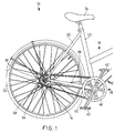
- Fig. 1 is a side view of a rear portion of a bicycle 10 that incorporates a particular embodiment of a locking bicycle cable connecting apparatus 14 according to the present invention.
- the rear portion of bicycle 10 includes a frame 18 with a seat tube 22 supporting a saddle 24, a pair of conventional chain stays 26, and a pair of conventional seat stays 30.
- a wheel 34 is rotatably supported by frame 18 around an axle 36 at the intersection of chain stays 26 and seat stays 30, and a crank assembly 38 having pedals 42 and a chain ring 46 is rotatably supported at the intersection of seat tube 22 and chain stays 26.
- a chain 50 engages chain ring 46 and wraps around a sprocket 54 that rotatably drives a conventional internal hub transmission 58 around axle 36.
- a Bowden-type control cable 62 is used to change speed stages of internal hub transmission 58 in a known manner.
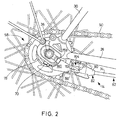
- Fig. 2 is a more detailed view of cable connecting apparatus 14.
- Bowden cable 62 includes an inner wire 70 that slides within an outer casing 74.
- Inner wire 70 connects directly to a conventional hub transmission clutch actuating ring 78, whereas outer casing 74 is terminated at an outer casing terminating member 82 (which functions as a first cable connecting member) which, in turn, is connected to a cable support 86 (which functions as a second cable connecting member) that also rotatably supports actuating ring 78.
- outer casing terminating member 82 includes an outer casing support portion 90 and a wire guiding projection 94 that is unthreaded along its entire length.
- Outer casing support portion 90 has the form of a generally convex casing support tube with a first end 96 and a second end 100.
- First end 96 has a casing support opening 104 (Fig. 5) for supporting outer casing 74 of Bowden cable 62.
- Casing support opening 104 also functions as a wire receiving passage that allows inner wire 70 to pass completely through outer casing support portion 90.
- casing support opening 104 extends into wire guiding projection.
- a finger operating member in the form of a finger operating tab 108 extends radially outwardly from outer casing support portion 90.
- Second end 100 of outer casing support portion 90 forms an abutment 112, and wire guiding projection 94 extends as one piece from abutment 112 along a first connecting member axis X which is coaxial with inner wire 70.
- Abutment 112 faces at least in part in a direction of first connecting member axis X away from first end 96.
- Wire guiding projection 94 is a generally tubular member that includes an inner wire passage 116 for receiving inner wire 70 therethrough, and a radially outwardly extending locking member 120 forming an abutment 124 facing at least in part in a direction of first connecting member axis X toward first end 96 of outer casing support portion 90.
- a stopper member 128 extends from locking member 120 in a circumferential direction for reasons discussed below.
- wire guiding projection 94 includes a straight first side wall 130 extending in the direction of first connecting member axis X, a straight second side wall 134 extending in the direction of first connecting member axis X parallel to first side wall 130, a third side wall 136 extending in a direction of first connecting member axis X, and a fourth side wall 138 extending in a direction of first connecting member axis X and opposite third side wall 136.
- a distance dl between first side wall 130 and second side wall 134 is less than a distance d2 between third side wall 136 and fourth side wall 138 for reasons discussed below.
- a retaining projection 150 immovably extends as one piece from abutment 112 of outer casing support portion 90 in a direction of first connecting member axis X, wherein retaining projection 150 is disposed radially outwardly from wire guiding projection 94 and terminates before wire guiding projection 94 in the direction of first connecting member axis X.
- retaining projection 150 forms an abutment 154 facing in a circumferential direction, an end wall 155 facing in the direction of first connecting member axis X, and a cam wall 156 facing in the circumferential direction and inclined relative to abutments 112 and 154.
- retaining projection 150 is spaced apart in the direction of first connecting member axis X from one of abutment 112 and abutment 124, in this case abutment 124. If desired, retaining projection 150 also may be radially spaced apart from wire guiding projection 94.
- a slot 155 extends through outer casing support portion 90 and wire guiding projection 94.
- outer casing terminating member 82 may be attached to cable 62 by placing inner wire 70 through slot 155 and then fitting outer casing 74 into casing support opening 104.
- cable support 86 includes a tubular portion 164 on one end defining a first connecting member opening 168 for receiving wire guiding projection 94 therethrough.
- Tubular portion 164 has a first tubular portion side wall 172 extending along a second connecting member axis Y, a second tubular portion side wall 178 substantially perpendicular to second connecting member axis Y, and a third tubular portion side wall 184 substantially perpendicular to second connecting member axis Y and opposite second tubular portion side wall 178.
- first connecting member axis X is coaxial with second connecting member axis Y when outer casing terminating member 82 is coupled to cable support 86 as shown in Fig. 2.
- First tubular portion side wall 172 defines a first passage 176 having a width W (Fig. 8) for passing locking member 120 in the direction of second connecting member axis Y away from first connecting member opening 168.
- Width W is greater than or equal to diameter dl but less than diameter d2 of wire guiding projection 94 for reasons discussed below.
- Second tubular portion side wall 178 forms a second passage 180 extending from first passage 176 in a circumferential direction.
- Third tubular portion side wall 184 includes a retaining recess 190 that has a shape complementary to retaining projection 150.
- retaining recess 190 forms an abutment 194 facing in a circumferential direction, a bottom wall 195 facing in the direction of second connecting member axis Y, and a cam wall 196 facing in the circumferential direction and inclined relative to abutment 194.
- a plate-shaped intermediate portion 160 extends from tubular portion 164 and terminates at an annular frame coupling member 159.
- Annular frame coupling member 159 has a central axis Z oriented substantially perpendicular to second connecting member axis Y.
- Annular frame coupling member 159 surrounds axle 36 of hub transmission 58 and rotatably supports actuating ring 78 in a known manner.
- Figs. 2 and 7 show cable connecting apparatus 14 in a locked state.
- abutment 112 abuts against third tubular portion side wall 184
- retaining projection 150 engages retaining recess 190 to inhibit rotation of outer casing terminating member 82 relative to cable support 86
- abutment 124 of locking member 120 abuts against second tubular portion side wall 178 to prevent outer casing terminating member 82 from moving away from cable support 86
- stopper member 128 abuts against a side wall 161 of intermediate portion 160 to further prevent rotation of outer casing terminating member 82 relative to cable support 86.
- outer casing terminating member 82 is rotated in the direction of the arrow shown in Fig. 9 with the help of finger operating tab 108.
- the force of such manual rotation is sufficient to cause cam wall 156 of retaining projection 150 to slide against cam wall 196 of retaining recess 190 until first side wall 130 and second side wall 134 of wire guiding projection 94 align with passage 176. Since the distance dl between first side wall 130 and second side wall 134 is less than or equal to the width W of passage 176, wire guiding projection 94 may be moved out of passage 176 to decouple outer casing terminating member 82 from cable support 86 as shown in Figs. 10 and 11. Outer casing terminating member 82 may be coupled to cable support 86 by reversing the procedure.
- Figs. 12-15 are oblique views of alternative embodiments of outer casing terminating member 82, represented by the reference numbers 82A-82D, respectively.
- locking member 120 is omitted.
- Such an omission is satisfactory when outer casing 74 of Bowden cable 62 exerts a sufficient biasing force against outer casing terminating members 82A-82D to prevent outer casing terminating members 82A-82D from moving away from cable support 86.
- finger operating tab 108 and slot 155 have been omitted in each embodiment. Omission of slot 155 allows the outer casing support portion and wire guiding projection in each embodiment to be circumferentially continuous.
- outer casing terminating member 82A in Fig. 12 is identical to outer casing terminating member 82 in the first embodiment except for the omission of finger operating tab 108, locking member 120 and slot 155.
- Outer casing terminating member 82B shown in Fig. 13 is substantially the same as outer casing terminating member 82A shown in Fig. 12 except that retaining projection 150 has been replaced by a retaining groove 200.
- Retaining groove 200 cooperates with a retaining projection 201 that replaces retaining groove 190 on a cable support 86'. Otherwise, this embodiment operates in the same manner as described for the first embodiment.
- Outer casing terminating member 82C shown in Fig. 14 is substantially the same as outer casing terminating member 82A in Fig. 12 except that an outer casing support portion 90C has a square shape.
- outer casing terminating member 82D shown in Fig. 15 is substantially the same as outer casing terminating member 82C in Fig. 14 except that a wire guiding projection 94D has a square shape.
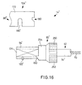
- Figs. 16-24 are views of an alternative embodiment of a cable connecting apparatus 14' according to the present invention, where structures that are the same as the structures in the first embodiment are numbered the same. Thus, it can be assumed that cable connecting apparatus 14' has the same structure as cable connecting apparatus 14 except where noted.
- an outer casing terminating member 82' includes a large diameter portion 250 for terminating outer casing 74 of Bowden cable 62 and a small diameter portion 254 that contains retaining projection 150.
- Large diameter portion 250 has a knurled outer peripheral surface 252 to facilitate gripping and rotation of outer casing terminating member 82'.
- a locking member 120' in the form of a locking pin extends radially outwardly from an intermediate portion of wire guiding projection 94'. Locking member 120' functions substantially the same as locking member 120 in the first embodiment.
- Tubular portion 164' of cable support 86'' differs from tubular portion 164 in the first embodiment in that passage 180 of the first embodiment is formed as a slot 180'.
- the assembly procedure for cable connecting apparatus 14' is the same as the assembly procedure of cable connecting apparatus 14.
- wire guiding projection 94' initially is inserted through passage 176 as shown in Fig. 17, and then outer casing terminating member 82' is rotated as shown in Fig. 18 until retaining projection 150 engages retaining recess 190 and locking member 120' is disposed in slot 180' as shown in Figs. 19-21.
- outer casing terminating member 82' is rotated in the direction of the arrow shown in Fig. 22 with the help of the knurled surface 252.
Landscapes
- Engineering & Computer Science (AREA)
- General Engineering & Computer Science (AREA)
- Mechanical Engineering (AREA)
- Health & Medical Sciences (AREA)
- Oral & Maxillofacial Surgery (AREA)
- Chemical & Material Sciences (AREA)
- Combustion & Propulsion (AREA)
- Transportation (AREA)
- Flexible Shafts (AREA)
- Motorcycle And Bicycle Frame (AREA)
- Axle Suspensions And Sidecars For Cycles (AREA)
Applications Claiming Priority (2)
| Application Number | Priority Date | Filing Date | Title |
|---|---|---|---|
| US514758 | 2000-02-28 | ||
| US09/514,758 US6324938B1 (en) | 2000-02-28 | 2000-02-28 | Locking bicycle cable connecting apparatus |
Publications (3)
| Publication Number | Publication Date |
|---|---|
| EP1127783A2 true EP1127783A2 (de) | 2001-08-29 |
| EP1127783A3 EP1127783A3 (de) | 2004-05-26 |
| EP1127783B1 EP1127783B1 (de) | 2005-07-27 |
Family
ID=24048564
Family Applications (1)
| Application Number | Title | Priority Date | Filing Date |
|---|---|---|---|
| EP01104313A Expired - Lifetime EP1127783B1 (de) | 2000-02-28 | 2001-02-22 | Kabelverbindungsvorrichtung für ein Fahrrad |
Country Status (7)
| Country | Link |
|---|---|
| US (1) | US6324938B1 (de) |
| EP (1) | EP1127783B1 (de) |
| JP (2) | JP2001271824A (de) |
| CN (2) | CN1118409C (de) |
| AT (1) | ATE300465T1 (de) |
| DE (1) | DE60112144T2 (de) |
| TW (1) | TW487666B (de) |
Cited By (1)
| Publication number | Priority date | Publication date | Assignee | Title |
|---|---|---|---|---|
| WO2022064252A1 (en) * | 2020-09-24 | 2022-03-31 | Johnson Electric Private Limited | Cable leveller device, headlamp leveller, and method of securing a cable thereto |
Families Citing this family (15)
| Publication number | Priority date | Publication date | Assignee | Title |
|---|---|---|---|---|
| US6349614B1 (en) * | 1998-11-06 | 2002-02-26 | Shimano, Inc. | Bicycle cable connector for splicing two cables in series |
| EP1388491B1 (de) * | 2002-08-08 | 2009-09-30 | SRAM Deutschland GmbH | Seilzugverbindung |
| DE10250435A1 (de) * | 2002-10-30 | 2004-05-19 | Sram Deutschland Gmbh | Nachstellvorrichtung |
| ITTO20030496A1 (it) * | 2003-06-30 | 2005-01-01 | Sila Holding Industriale Spa | Dispositivo di collegamento per un'estremita' di un cavo di azionamento. |
| DE10341037B4 (de) * | 2003-09-03 | 2006-11-09 | GM Global Technology Operations, Inc., Detroit | Bowdenzug für ein Kraftfahrzeug |
| US7152498B2 (en) * | 2003-12-03 | 2006-12-26 | Shimano Inc. | Bicycle control cable fixing device |
| CN102182748A (zh) * | 2011-04-27 | 2011-09-14 | 奇瑞汽车股份有限公司 | 一种拉线卡接头固定结构 |
| US9651138B2 (en) | 2011-09-30 | 2017-05-16 | Mtd Products Inc. | Speed control assembly for a self-propelled walk-behind lawn mower |
| CN103122920B (zh) * | 2011-11-21 | 2016-04-27 | 中国航空工业集团公司沈阳发动机设计研究所 | 一种带铜质内套的过隔板式反馈钢索结构 |
| ITMI20121057A1 (it) * | 2012-06-18 | 2013-12-19 | Campagnolo Srl | Guidacavo per un manubrio di bicicletta e manubrio provvisto di guidacavo |
| CN103847922A (zh) * | 2012-12-07 | 2014-06-11 | 捷安特(昆山)有限公司 | 自行车变速器引线导向机构 |
| USD808306S1 (en) * | 2015-07-07 | 2018-01-23 | Yuan-Hung WEN | Bicycle cable |
| US10473186B2 (en) * | 2015-10-12 | 2019-11-12 | Hi-Lex Corporation | Coupling structure |
| EP3267054B1 (de) | 2016-07-07 | 2019-02-20 | Goodrich Actuation Systems Limited | Steuerkabelschnellanschluss |
| IT201700042443A1 (it) * | 2017-04-18 | 2018-10-18 | Magneti Marelli Spa | Dispositivo per il collegamento di un cavo bowden ad una leva di azionamento di una frizione servoassistita |
Citations (1)
| Publication number | Priority date | Publication date | Assignee | Title |
|---|---|---|---|---|
| US4833937A (en) | 1985-04-22 | 1989-05-30 | Shimano Industrial Company Limited | Adjusting device for a control cable for a bicycle |
Family Cites Families (33)
| Publication number | Priority date | Publication date | Assignee | Title |
|---|---|---|---|---|
| US3020778A (en) | 1954-08-05 | 1962-02-13 | Frithjof C Davidson | Bicycle gear shift control |
| GB956168A (en) * | 1962-01-24 | 1964-04-22 | Cyclo Gear Co Ltd | Improvements relating to gear and cable combinations |
| JPS5432089Y2 (de) * | 1975-08-05 | 1979-10-05 | ||
| JPS5639776Y2 (de) * | 1978-03-16 | 1981-09-17 | ||
| JPS55104179U (de) * | 1979-01-18 | 1980-07-21 | ||
| JPS6020823Y2 (ja) * | 1980-03-29 | 1985-06-21 | 日本ケ−ブル・システム株式会社 | コントロ−ルケ−ブルの係止金具 |
| DE3233433A1 (de) | 1982-09-09 | 1984-03-15 | Fichtel & Sachs Ag | Verbindungseinrichtung fuer einen betaetigungsschaltzug |
| JPS6137508A (ja) | 1984-07-31 | 1986-02-22 | Mazda Motor Corp | 自動車のリヤサスペンシヨン装置 |
| JPS6145614A (ja) | 1984-08-09 | 1986-03-05 | Olympus Optical Co Ltd | 自動増幅率制御回路 |
| JPH0674075B2 (ja) * | 1985-04-22 | 1994-09-21 | 島野工業株式会社 | 自転車用操作索の調整装置 |
| JPS6240327A (ja) | 1985-08-14 | 1987-02-21 | Agency Of Ind Science & Technol | イオン分離法 |
| JPS62117192U (de) * | 1985-08-22 | 1987-07-25 | ||
| JPH026252Y2 (de) * | 1985-11-15 | 1990-02-15 | ||
| JPS6380315A (ja) | 1986-09-25 | 1988-04-11 | Hitachi Ltd | 端末装置 |
| JP2784580B2 (ja) | 1988-11-22 | 1998-08-06 | ジーイー横河メディカルシステム株式会社 | ピント合せ機構 |
| JPH02271035A (ja) * | 1989-04-13 | 1990-11-06 | Nifco Inc | アクセルケーブルの接続装置 |
| US5156064A (en) * | 1991-05-21 | 1992-10-20 | Handy & Harman Automotive Group, Inc. | Cable length adjustment device |
| US5222411A (en) * | 1991-05-21 | 1993-06-29 | Handy & Harmon Automotive Group | Miniature core adjust device |
| JP2546463Y2 (ja) | 1991-06-12 | 1997-09-03 | 株式会社シマノ | 自転車用の操作ワイヤ固定用構造 |
| JPH0532820A (ja) | 1991-07-31 | 1993-02-09 | Mitsui Eng & Shipbuild Co Ltd | 制振方法 |
| US5706706A (en) * | 1992-04-06 | 1998-01-13 | Hnk Spring Co., Ltd. | Length-adjusting device for control cable |
| JPH06147215A (ja) * | 1992-10-31 | 1994-05-27 | Nhk Spring Co Ltd | コントロールケーブルの長さ調整装置 |
| EP0606653A1 (de) | 1993-01-04 | 1994-07-20 | Texas Instruments Incorporated | Verteilter Feld-programmierbarer Speicherprozessor |
| US5564311A (en) | 1995-01-27 | 1996-10-15 | Chen; Tse-Min | Fastening seat of bicycle brake lever |
| US5809840A (en) * | 1995-02-14 | 1998-09-22 | Shimano, Inc. | Protective cap system for bicycle cable |
| US5613406A (en) * | 1995-10-26 | 1997-03-25 | Teleflex Incorporated | Rotating slide-n-snap |
| US5615584A (en) * | 1995-11-21 | 1997-04-01 | Teleflex Incorporated | Slide n' snap with living hinge lock |
| IT1286286B1 (it) * | 1996-03-29 | 1998-07-08 | Roltra Morse Spa | Dispositivo di fissaggio per un tirante di azionamento. |
| US5875687A (en) * | 1996-04-10 | 1999-03-02 | Shimano, Inc. | Protective cap system for bicycle cable |
| US5674142A (en) * | 1996-04-16 | 1997-10-07 | Sram Corporation | Control cable adjustment device |
| DE29608010U1 (de) | 1996-05-03 | 1996-07-25 | Fichtel & Sachs Ag | Gehäuse für einen Betätigungszug zum Schalten der Gangstufen eines Fahrradgetriebes |
| BE1010904A6 (nl) * | 1997-02-05 | 1999-03-02 | Drijbooms Wilfried Frieda Albe | Op een fiets gemonteerde versnellingskabeloverbrenging en daarbij gebruikte eindconstructies. |
| JP3142247B2 (ja) * | 1997-05-08 | 2001-03-07 | 株式会社シマノ | 自転車用内装変速ハブ |
-
2000
- 2000-02-28 US US09/514,758 patent/US6324938B1/en not_active Expired - Fee Related
- 2000-11-29 TW TW089125373A patent/TW487666B/zh not_active IP Right Cessation
- 2000-12-15 CN CN00135974A patent/CN1118409C/zh not_active Expired - Fee Related
-
2001
- 2001-02-22 DE DE60112144T patent/DE60112144T2/de not_active Expired - Fee Related
- 2001-02-22 AT AT01104313T patent/ATE300465T1/de not_active IP Right Cessation
- 2001-02-22 EP EP01104313A patent/EP1127783B1/de not_active Expired - Lifetime
- 2001-02-26 JP JP2001050714A patent/JP2001271824A/ja active Pending
-
2003
- 2003-01-08 CN CN03100976A patent/CN1441173A/zh active Pending
-
2005
- 2005-10-03 JP JP2005290537A patent/JP2006077992A/ja active Pending
Patent Citations (1)
| Publication number | Priority date | Publication date | Assignee | Title |
|---|---|---|---|---|
| US4833937A (en) | 1985-04-22 | 1989-05-30 | Shimano Industrial Company Limited | Adjusting device for a control cable for a bicycle |
Cited By (1)
| Publication number | Priority date | Publication date | Assignee | Title |
|---|---|---|---|---|
| WO2022064252A1 (en) * | 2020-09-24 | 2022-03-31 | Johnson Electric Private Limited | Cable leveller device, headlamp leveller, and method of securing a cable thereto |
Also Published As
| Publication number | Publication date |
|---|---|
| CN1441173A (zh) | 2003-09-10 |
| EP1127783B1 (de) | 2005-07-27 |
| CN1311131A (zh) | 2001-09-05 |
| US6324938B1 (en) | 2001-12-04 |
| JP2001271824A (ja) | 2001-10-05 |
| ATE300465T1 (de) | 2005-08-15 |
| EP1127783A3 (de) | 2004-05-26 |
| DE60112144T2 (de) | 2006-05-24 |
| JP2006077992A (ja) | 2006-03-23 |
| CN1118409C (zh) | 2003-08-20 |
| DE60112144D1 (de) | 2005-09-01 |
| TW487666B (en) | 2002-05-21 |
Similar Documents
| Publication | Publication Date | Title |
|---|---|---|
| EP1127783A2 (de) | Kabelverbindungsvorrichtung für ein Fahrrad | |
| US6510760B2 (en) | Bicycle cable connector for splicing two cables in series | |
| US8042427B2 (en) | Bicycle shifter | |
| EP1106496A2 (de) | Schalteinrichtung für ein Fahrradgetriebe | |
| US6866604B2 (en) | Multiple level sprocket support for a bicycle | |
| US7240585B2 (en) | Drive mechanism for a bicycle transmission assist mechanism | |
| RU2220067C2 (ru) | Механизм переключения передач велосипеда (варианты) | |
| US8770061B2 (en) | Crank assembly for a bicycle bottom bracket assembly, shaft and crank arm thereof | |
| CN114104184B (zh) | 用于具有链式换挡装置的自行车的多层小齿轮组件和后轮组件 | |
| US20040014541A1 (en) | Actuator for a bicycle gear-shift | |
| US11591043B2 (en) | Sprocket-carrying body and sub-assembly of sprocket-carrying body and cogset for a bicycle rear wheel | |
| FR2513208A1 (fr) | Pedalier pour une bicyclette | |
| US6364334B1 (en) | Bicycle frame | |
| US11592097B2 (en) | Sub-assembly sprocket-carrying body and cogset for a bicycle rear wheel, ring nut for fixing such a sub-assembly and method for fixing a cogset to a sprocket-carrying body | |
| CN104512520A (zh) | 拨链器 | |
| CN100577499C (zh) | 自行车部件安装结构 | |
| TW200827239A (en) | Bicycle rear derailleur | |
| EP1792819A1 (de) | Tretkurbellager-Anordnung | |
| EP3341279A2 (de) | Übertragungselement zur übertragung eines drehmomentes von einem kettenrad an eine radnabe | |
| EP1657153A2 (de) | Kurbeldeckelvorrichtung für ein Fahrrad | |
| TWI585002B (zh) | 撥鏈器 | |
| EP1747912A2 (de) | Fixierungsvorrichtung für Fahrradnabe | |
| US7401535B2 (en) | Twist-grip bicycle shifter | |
| EP1642817B1 (de) | Schwingenstruktur in Zwei- und Dreirädern mit Motor | |
| JPH03208786A (ja) | 自動二輪車のハンドル装置 |
Legal Events
| Date | Code | Title | Description |
|---|---|---|---|
| PUAI | Public reference made under article 153(3) epc to a published international application that has entered the european phase |
Free format text: ORIGINAL CODE: 0009012 |
|
| AK | Designated contracting states |
Kind code of ref document: A2 Designated state(s): AT BE CH CY DE DK ES FI FR GB GR IE IT LI LU MC NL PT SE TR |
|
| AX | Request for extension of the european patent |
Free format text: AL;LT;LV;MK;RO;SI |
|
| PUAL | Search report despatched |
Free format text: ORIGINAL CODE: 0009013 |
|
| RIC1 | Information provided on ipc code assigned before grant |
Ipc: 7F 16C 1/22 B Ipc: 7F 16C 1/26 B Ipc: 7B 62M 25/02 A |
|
| AK | Designated contracting states |
Kind code of ref document: A3 Designated state(s): AT BE CH CY DE DK ES FI FR GB GR IE IT LI LU MC NL PT SE TR |
|
| AX | Request for extension of the european patent |
Extension state: AL LT LV MK RO SI |
|
| 17P | Request for examination filed |
Effective date: 20040630 |
|
| 17Q | First examination report despatched |
Effective date: 20040730 |
|
| GRAP | Despatch of communication of intention to grant a patent |
Free format text: ORIGINAL CODE: EPIDOSNIGR1 |
|
| AKX | Designation fees paid |
Designated state(s): AT BE CH CY DE DK ES FI FR GB GR IE IT LI LU MC NL PT SE TR |
|
| GRAS | Grant fee paid |
Free format text: ORIGINAL CODE: EPIDOSNIGR3 |
|
| GRAA | (expected) grant |
Free format text: ORIGINAL CODE: 0009210 |
|
| AK | Designated contracting states |
Kind code of ref document: B1 Designated state(s): AT BE CH CY DE DK ES FI FR GB GR IE IT LI LU MC NL PT SE TR |
|
| PG25 | Lapsed in a contracting state [announced via postgrant information from national office to epo] |
Ref country code: LI Free format text: LAPSE BECAUSE OF FAILURE TO SUBMIT A TRANSLATION OF THE DESCRIPTION OR TO PAY THE FEE WITHIN THE PRESCRIBED TIME-LIMIT Effective date: 20050727 Ref country code: CH Free format text: LAPSE BECAUSE OF FAILURE TO SUBMIT A TRANSLATION OF THE DESCRIPTION OR TO PAY THE FEE WITHIN THE PRESCRIBED TIME-LIMIT Effective date: 20050727 Ref country code: BE Free format text: LAPSE BECAUSE OF FAILURE TO SUBMIT A TRANSLATION OF THE DESCRIPTION OR TO PAY THE FEE WITHIN THE PRESCRIBED TIME-LIMIT Effective date: 20050727 Ref country code: AT Free format text: LAPSE BECAUSE OF FAILURE TO SUBMIT A TRANSLATION OF THE DESCRIPTION OR TO PAY THE FEE WITHIN THE PRESCRIBED TIME-LIMIT Effective date: 20050727 Ref country code: TR Free format text: LAPSE BECAUSE OF FAILURE TO SUBMIT A TRANSLATION OF THE DESCRIPTION OR TO PAY THE FEE WITHIN THE PRESCRIBED TIME-LIMIT Effective date: 20050727 Ref country code: FI Free format text: LAPSE BECAUSE OF FAILURE TO SUBMIT A TRANSLATION OF THE DESCRIPTION OR TO PAY THE FEE WITHIN THE PRESCRIBED TIME-LIMIT Effective date: 20050727 |
|
| REG | Reference to a national code |
Ref country code: GB Ref legal event code: FG4D |
|
| REG | Reference to a national code |
Ref country code: CH Ref legal event code: EP |
|
| REG | Reference to a national code |
Ref country code: IE Ref legal event code: FG4D |
|
| REF | Corresponds to: |
Ref document number: 60112144 Country of ref document: DE Date of ref document: 20050901 Kind code of ref document: P |
|
| PG25 | Lapsed in a contracting state [announced via postgrant information from national office to epo] |
Ref country code: GR Free format text: LAPSE BECAUSE OF FAILURE TO SUBMIT A TRANSLATION OF THE DESCRIPTION OR TO PAY THE FEE WITHIN THE PRESCRIBED TIME-LIMIT Effective date: 20051027 Ref country code: DK Free format text: LAPSE BECAUSE OF FAILURE TO SUBMIT A TRANSLATION OF THE DESCRIPTION OR TO PAY THE FEE WITHIN THE PRESCRIBED TIME-LIMIT Effective date: 20051027 Ref country code: SE Free format text: LAPSE BECAUSE OF FAILURE TO SUBMIT A TRANSLATION OF THE DESCRIPTION OR TO PAY THE FEE WITHIN THE PRESCRIBED TIME-LIMIT Effective date: 20051027 |
|
| PG25 | Lapsed in a contracting state [announced via postgrant information from national office to epo] |
Ref country code: ES Free format text: LAPSE BECAUSE OF FAILURE TO SUBMIT A TRANSLATION OF THE DESCRIPTION OR TO PAY THE FEE WITHIN THE PRESCRIBED TIME-LIMIT Effective date: 20051107 |
|
| PG25 | Lapsed in a contracting state [announced via postgrant information from national office to epo] |
Ref country code: PT Free format text: LAPSE BECAUSE OF FAILURE TO SUBMIT A TRANSLATION OF THE DESCRIPTION OR TO PAY THE FEE WITHIN THE PRESCRIBED TIME-LIMIT Effective date: 20051227 |
|
| REG | Reference to a national code |
Ref country code: CH Ref legal event code: PL |
|
| PGFP | Annual fee paid to national office [announced via postgrant information from national office to epo] |
Ref country code: FR Payment date: 20060215 Year of fee payment: 6 Ref country code: NL Payment date: 20060215 Year of fee payment: 6 |
|
| PGFP | Annual fee paid to national office [announced via postgrant information from national office to epo] |
Ref country code: IE Payment date: 20060223 Year of fee payment: 6 |
|
| PG25 | Lapsed in a contracting state [announced via postgrant information from national office to epo] |
Ref country code: MC Free format text: LAPSE BECAUSE OF NON-PAYMENT OF DUE FEES Effective date: 20060228 Ref country code: LU Free format text: LAPSE BECAUSE OF NON-PAYMENT OF DUE FEES Effective date: 20060228 |
|
| PGFP | Annual fee paid to national office [announced via postgrant information from national office to epo] |
Ref country code: IT Payment date: 20060228 Year of fee payment: 6 |
|
| PGFP | Annual fee paid to national office [announced via postgrant information from national office to epo] |
Ref country code: DE Payment date: 20060425 Year of fee payment: 6 |
|
| ET | Fr: translation filed | ||
| PLBE | No opposition filed within time limit |
Free format text: ORIGINAL CODE: 0009261 |
|
| STAA | Information on the status of an ep patent application or granted ep patent |
Free format text: STATUS: NO OPPOSITION FILED WITHIN TIME LIMIT |
|
| 26N | No opposition filed |
Effective date: 20060428 |
|
| GBPC | Gb: european patent ceased through non-payment of renewal fee |
Effective date: 20070222 |
|
| NLV4 | Nl: lapsed or anulled due to non-payment of the annual fee |
Effective date: 20070901 |
|
| REG | Reference to a national code |
Ref country code: IE Ref legal event code: MM4A |
|
| REG | Reference to a national code |
Ref country code: FR Ref legal event code: ST Effective date: 20071030 |
|
| PG25 | Lapsed in a contracting state [announced via postgrant information from national office to epo] |
Ref country code: NL Free format text: LAPSE BECAUSE OF NON-PAYMENT OF DUE FEES Effective date: 20070901 Ref country code: IE Free format text: LAPSE BECAUSE OF NON-PAYMENT OF DUE FEES Effective date: 20070222 Ref country code: DE Free format text: LAPSE BECAUSE OF NON-PAYMENT OF DUE FEES Effective date: 20070901 |
|
| PG25 | Lapsed in a contracting state [announced via postgrant information from national office to epo] |
Ref country code: FR Free format text: LAPSE BECAUSE OF NON-PAYMENT OF DUE FEES Effective date: 20070228 Ref country code: GB Free format text: LAPSE BECAUSE OF NON-PAYMENT OF DUE FEES Effective date: 20070222 |
|
| PGFP | Annual fee paid to national office [announced via postgrant information from national office to epo] |
Ref country code: GB Payment date: 20060221 Year of fee payment: 6 |
|
| PG25 | Lapsed in a contracting state [announced via postgrant information from national office to epo] |
Ref country code: CY Free format text: LAPSE BECAUSE OF FAILURE TO SUBMIT A TRANSLATION OF THE DESCRIPTION OR TO PAY THE FEE WITHIN THE PRESCRIBED TIME-LIMIT Effective date: 20050727 |
|
| PG25 | Lapsed in a contracting state [announced via postgrant information from national office to epo] |
Ref country code: IT Free format text: LAPSE BECAUSE OF NON-PAYMENT OF DUE FEES Effective date: 20070222 |