EP1127985A2 - Machine de construction, en particulier excavatrice - Google Patents
Machine de construction, en particulier excavatrice Download PDFInfo
- Publication number
- EP1127985A2 EP1127985A2 EP01104120A EP01104120A EP1127985A2 EP 1127985 A2 EP1127985 A2 EP 1127985A2 EP 01104120 A EP01104120 A EP 01104120A EP 01104120 A EP01104120 A EP 01104120A EP 1127985 A2 EP1127985 A2 EP 1127985A2
- Authority
- EP
- European Patent Office
- Prior art keywords
- working
- machine according
- working machine
- arm
- cylinders
- Prior art date
- Legal status (The legal status is an assumption and is not a legal conclusion. Google has not performed a legal analysis and makes no representation as to the accuracy of the status listed.)
- Withdrawn
Links
- 239000007787 solid Substances 0.000 claims 1
- 230000007246 mechanism Effects 0.000 description 9
- 230000008859 change Effects 0.000 description 2
- 230000003319 supportive effect Effects 0.000 description 2
- 230000002411 adverse Effects 0.000 description 1
- 238000009412 basement excavation Methods 0.000 description 1
- 238000005452 bending Methods 0.000 description 1
- 230000005540 biological transmission Effects 0.000 description 1
- 230000015572 biosynthetic process Effects 0.000 description 1
- 230000007613 environmental effect Effects 0.000 description 1
- 230000003993 interaction Effects 0.000 description 1
- 230000008439 repair process Effects 0.000 description 1
Images

Classifications
-
- E—FIXED CONSTRUCTIONS
- E02—HYDRAULIC ENGINEERING; FOUNDATIONS; SOIL SHIFTING
- E02F—DREDGING; SOIL-SHIFTING
- E02F3/00—Dredgers; Soil-shifting machines
- E02F3/04—Dredgers; Soil-shifting machines mechanically-driven
- E02F3/96—Dredgers; Soil-shifting machines mechanically-driven with arrangements for alternate or simultaneous use of different digging elements
- E02F3/966—Dredgers; Soil-shifting machines mechanically-driven with arrangements for alternate or simultaneous use of different digging elements of hammer-type tools
-
- E—FIXED CONSTRUCTIONS
- E02—HYDRAULIC ENGINEERING; FOUNDATIONS; SOIL SHIFTING
- E02F—DREDGING; SOIL-SHIFTING
- E02F3/00—Dredgers; Soil-shifting machines
- E02F3/04—Dredgers; Soil-shifting machines mechanically-driven
- E02F3/28—Dredgers; Soil-shifting machines mechanically-driven with digging tools mounted on a dipper- or bucket-arm, i.e. there is either one arm or a pair of arms, e.g. dippers, buckets
- E02F3/30—Dredgers; Soil-shifting machines mechanically-driven with digging tools mounted on a dipper- or bucket-arm, i.e. there is either one arm or a pair of arms, e.g. dippers, buckets with a dipper-arm pivoted on a cantilever beam, i.e. boom
- E02F3/304—Dredgers; Soil-shifting machines mechanically-driven with digging tools mounted on a dipper- or bucket-arm, i.e. there is either one arm or a pair of arms, e.g. dippers, buckets with a dipper-arm pivoted on a cantilever beam, i.e. boom with the dipper-arm slidably mounted on the boom
Definitions
- the invention relates to a work machine, in particular an excavator, the is preferably used as an excavator and for general cargo handling.
- a variety of different machines are known, which are designed either as excavators or for general cargo handling. Although it is possible in principle to use such a machine designed for one purpose for the other purpose, there is the problem that an excavator is designed for powerful, tearing use, the excavator operation, and not for fast lifting of loads.
- hydraulic cylinders are usually arranged on a working arm, which have a large oil column, for the mostly short but powerful pulling movements of the excavator bucket.
- the small oil column of the hydraulic cylinders is intended for a lifting movement of the excavator bucket. There is therefore only a limited force available for this lifting movement. As a result, the movements of an excavator cannot be used for effective general cargo handling.
- the invention has for its object to propose a machine that is equally suitable for excavator operations as well as for general cargo handling and can do both jobs efficiently.
- the telescope is at least three-part telescope is formed.
- the telescope is automatically in the respective position is designed to be lockable.
- each of the two cylinders for a particular purpose is provided and the other cylinder then as a push rod and / or pull rod serves. It is also conceivable for both cylinders to work together in certain cases Movements of the working arm.
- the Working tool arranged from the end of the working arm remote from the machine is designed to be interchangeable.
- a further development of the invention also teaches as very advantageous that the Tool is designed to be folded away.
- the tool is simple and requires little effort from the Removable working position; the tool is secure on the working arm in one Quiet location housed.
- Tool is designed to be retractable into the working arm.
- a further development of the invention is that at least one other Tool is arranged on the working arm.
- Tools on the working arm are arranged so that when retracting or extending the Telescope of the working arm the tools are changed.
- the tool unit is designed to be exchangeable, foldable or displaceable overall.
- Telescopic cylinders with at least two push / pull rods are provided.
- Lever devices on the working arm engage at least two cylinders, one of which at least one for each of at least two applications of the Work arm are provided.
- An advantageous development of the invention is also that cylinders in Working arm are arranged.
- cylinders are arranged within the unit of tool and actuators.
- Another advantageous embodiment of the invention is that on the Machine away end of the working arm a support element, preferably removable, foldable or slidable, is arranged.
- Such a support element is mainly used in difficult terrain; around itself moving out of a swampy hole with an excavator is extremely helpful if you can support yourself with the working arm.
- an example Plate conceivable as a support element. Because the support element is removable, can be folded away or pushed away, it prevents normal Use of the machine is not.
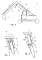
- FIG. 1 denotes a work machine with a work arm 2.
- a Tool 3 On from Drive of the working machine 1 facing away from the end of the working arm 2 is a Tool 3 arranged, which is designed as an excavator shovel in this illustration.
- the working arm 2 is in a lower main arm 4 and an upper boom 5 divided, which are interconnected via a joint 6.
- the inclination of the Main arm 4 can be changed via a hydraulic mechanism, not shown become.
- the boom 5 is relative to the main arm 4 by a on the main arm 4th arranged hydraulic cylinder 7 moves.
- the rod 8 of the cylinder 7 shows in Direction of the boom 5, whereby the lowering, i.e.
- pulling movement of the Boom 5 corresponds to the large oil column of the hydraulic cylinder 7, whereby again a greater power yield can be achieved with pulling movement.
- At the Boom 5 is also at least one in the vicinity of the tool 3 Hydraulic cylinder 9 attached to the tool in the direction of the boom can swing. This arrangement represents that of a typical excavator.
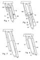
- a part of a work machine is shown, the main arm 14 of the Working arm 12 as a telescope with an outer part 15 and one in this outer part 15 inserted inner part 16 is equipped.
- On the outer part 15 is a Locking mechanism 17 attached, which fixes the inner part 16 in the outer part 15 and prevents accidental shifting.
- the Force transfer between outer part 15 and inner part 16 improved.
- On the top and Bottom of the main arm 14 cylinders 18 and 19 are arranged.
- the cylinder 18th attacks via a receptacle 30 on the inner part 16.
- the cylinder 19 is slidable in a rail 31 mounted on the outer part 15 and is in its working position over a Locking system, not shown, locked.
- the cylinder 19 can the cylinder 18 support in excavator operation and vice versa, the cylinder 18 can the cylinder 19 support with general cargo handling.
- a cylinder 18 is provided on the upper side of the main arm 14, whereas two cylinders 191 and 192 are arranged for general cargo handling, which are connected to one another via a lever 22, which has one end is rotatably mounted on the outer part 15.
- a lever 22 which has one end is rotatably mounted on the outer part 15.
- a telescopic cylinder 32 To push or pull the Inner part 16 from or into the outer part 15 is a telescopic cylinder 32 below the Cylinder 18 attached.
- the telescopic cylinder 32 also changes the position of the Point of attack of the cylinder 18 on the outer part 15.
- FIGS. 6 and 7 the cylinders 18 and 19 are each as Telescopic cylinder formed, each as in Fig. 2 and 3 on the upper or Bottom of the main arm are attached
- the cylinder 18 is another Cylinder 181 assigned longitudinally, which supports the cylinder 18 and any Length compensation.
- the working arm 2 in FIGS. 8 and 9 shows yet another arrangement of the Hydraulic cylinder 18 and 19.
- the rod 23 of the cylinder 19 is on the outer part 15 of the Main arm 14 attached.
- the first cylinder is - like cylinder 7 from FIG. 1 - for pulling movement of the boom 5 is provided, whereas the second cylinder for lifting movements of the boom 5 is formed when handling general cargo.
- the second cylinder also acts with its when the boom 5 is lifting large oil column, which also results in a large power yield.
- the second The cylinder remains in a defined position when the excavator is used whereas the first cylinder when using the work machine 1 for General cargo handling remains in a defined position. If the inner part 16 pulled out of the outer part 15 as far as possible, so the first cylinder is up to a defined position extended around the larger radius of the main arm 14 compensate. Now only the second cylinder works for lifting movements the boom 5.
- first and second cylinders engage a lever that is rotatably supported at one end on the outer part 15. If the inner part is 16 pushed as far as possible into the outer part 15, so the first cylinder is supported additionally directly from the outer part 15, which causes the large forces that occur when excavator operation of work machine 1 is particularly good from the first cylinder to the Main arm 14 are transmitted. The lever is thereby in the excavator operation relieved. Due to the inner part 16 pushed into the outer part 15 Main arm 14 extremely stable against bending stress. If the inner part 16 pushed as far as possible out of the outer part 15 and with the Locking mechanism 17 locked, so the inner part 16 can be released from the outer part 15 of the locking mechanism 17.
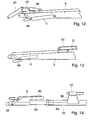
- the tool 3 is on the boom 5 of the working arm 4 by means of a joint 39 attached.
- the hydraulic cylinder 9 acts in the embodiment of FIG. 10 via a Lever arrangement 41 on the tool 3, not shown here.
- the cylinder 9 is also attached laterally to the boom around another tool holder 42, the on a rail arrangement 43 on the top of the boom 5 is stored to make room.
- the tool holder 42 is in its end positions lockable to prevent accidental movement of the tool holder 42 to prevent on the rail assembly 43.
- 11 shows the tool holder 42 in their working position.
- a chain mechanism 44 is indicated, which to move the tool holder between the working position and the rest position can
- FIG. 12 Another tool holder 45 shown in FIG. 12 is provided with a Hydraulic cylinder 46 equipped, which acts on a lever 47.
- This lever 47 capable of an excavator shovel used as tool 3, not shown here Act.
- the hydraulic cylinder 9 acts in this embodiment on the Lever arrangement 48 acting on the underside of the boom 5.
- the hydraulic cylinder 9 is in the Boom 5 arranged.
- the movements of the cylinder 9 are over a Lever arrangement 49 led out of the boom 5.
- On the top of Boom 5 is in a displaceable tool holder 50 parallel to Hydraulic cylinder 51 aligned sliding direction.
- FIG. 14 shows a boom 52, the one for receiving Tool 3 provided joint 39 is provided on an inner telescopic part 53. This inner part can be pushed into its outer part 54. On the inner part 53 of the telescope also the hydraulic cylinder 9 mounted in a receptacle 55. The boom 52 will by a longitudinally displaceable carriage 56 which includes another Tool holder 57 includes.
- a support plate 58 is attached to the end of the telescopic inner part 53, which it enables the working machine with the help of the boom 52 on loose ground can be supported. This is especially helpful when the work machine is on difficult terrain, such as moving on slopes or in wetlands must become.
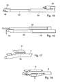
- a telescopic cylinder 59 is on the tool holder Top of the boom 52 is provided, which over the end of the telescopic inner part 53rd protrude and with a catch 60 at this end of the telescopic inner part 53 can support, as shown in Fig. 16. This will Telescopic cylinder 59 stiffened laterally to its direction of movement. 16 is also shown a further support plate 61, with which it is also possible to Anchor bracket 52 pulling to anchor in the ground.
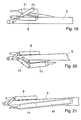
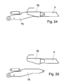
- a boom 5 of a working arm 4 is shown, on the upper side one Chisel device 71 is arranged foldable.
- the chisel device is included Folded onto the boom 5 with the help of an intermediate piece.
- the chisel device 71 shown in FIG. 18 is on the underside of the Boom 5 slidably attached.
- the chisel device 71 is used shifted forward into the working position, where this prevents accidental Moving is secured.
- On the top of the boom 5 is the Hydraulic cylinder 9 for actuating other tools 3, not shown appropriate.
- the chisel device 71 has a Lever mechanism 73 mounted on the top of the boom 5, the Chisel device is folded over the hydraulic cylinder 9.
- FIG. 20 The embodiment in FIG. 20 is similar to that in FIG. 19. Here, however, the Chisel device 71 via a lever mechanism 74 on the underside of the Boom 5 folded into a rest position.
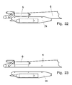
- FIGS. 22 and 23 Another embodiment uses a docked on the bottom of the boom 5 Chisel unit 74, which includes a longitudinally displaceable chisel device 71.
- This Chisel unit 74 can be used to reduce weight when not in use for a long time Boom 5 can be removed from the boom 5, as shown in FIGS. 22 and 23 is shown.
Landscapes
- Engineering & Computer Science (AREA)
- Mechanical Engineering (AREA)
- Mining & Mineral Resources (AREA)
- Civil Engineering (AREA)
- General Engineering & Computer Science (AREA)
- Structural Engineering (AREA)
- Shovels (AREA)
- Earth Drilling (AREA)
- Jib Cranes (AREA)
Applications Claiming Priority (4)
| Application Number | Priority Date | Filing Date | Title |
|---|---|---|---|
| DE10008112 | 2000-02-22 | ||
| DE10008112 | 2000-02-22 | ||
| DE2000144729 DE10044729A1 (de) | 2000-09-08 | 2000-09-08 | Arbeitsmaschine, insbesondere Bagger |
| DE10044729 | 2000-09-08 |
Publications (2)
| Publication Number | Publication Date |
|---|---|
| EP1127985A2 true EP1127985A2 (fr) | 2001-08-29 |
| EP1127985A3 EP1127985A3 (fr) | 2003-02-05 |
Family
ID=26004463
Family Applications (1)
| Application Number | Title | Priority Date | Filing Date |
|---|---|---|---|
| EP01104120A Withdrawn EP1127985A3 (fr) | 2000-02-22 | 2001-02-21 | Machine de construction, en particulier excavatrice |
Country Status (1)
| Country | Link |
|---|---|
| EP (1) | EP1127985A3 (fr) |
Cited By (1)
| Publication number | Priority date | Publication date | Assignee | Title |
|---|---|---|---|---|
| DE102008026173A1 (de) * | 2008-06-01 | 2009-12-03 | Technische Universität Dresden | Arbeitsausleger für ein Vielzweckfahrzeug |
Family Cites Families (3)
| Publication number | Priority date | Publication date | Assignee | Title |
|---|---|---|---|---|
| US3670910A (en) * | 1970-07-23 | 1972-06-20 | Donald George Shaw | Mobile load handling or lifting machines |
| US3977547A (en) * | 1971-06-07 | 1976-08-31 | Holopainen Vaino J | Material handling apparatus |
| DE69213215T2 (de) * | 1992-05-04 | 1997-01-23 | Manitou Costr Ind Srl | Beweglicher Mehrzweck-Frontlader und Bagger |
-
2001
- 2001-02-21 EP EP01104120A patent/EP1127985A3/fr not_active Withdrawn
Cited By (1)
| Publication number | Priority date | Publication date | Assignee | Title |
|---|---|---|---|---|
| DE102008026173A1 (de) * | 2008-06-01 | 2009-12-03 | Technische Universität Dresden | Arbeitsausleger für ein Vielzweckfahrzeug |
Also Published As
| Publication number | Publication date |
|---|---|
| EP1127985A3 (fr) | 2003-02-05 |
Similar Documents
| Publication | Publication Date | Title |
|---|---|---|
| EP1950353B1 (fr) | Dispositif d'excavation du sol | |
| DE10297276T5 (de) | Aufsatzkopplungsvorrichtung für Schwermaschinen | |
| DE102021105851A1 (de) | Steuereinheitsanordnung mit einstellbarer breite | |
| DE69203917T2 (de) | Werkzeugwechselvorrichtung einer Erdbaumaschine. | |
| EP3401444A1 (fr) | Dispositif d'excavation de tranchée et procédé de fabrication de tranchées dans le sol | |
| DE2542305C3 (de) | Bodenaushubgerät | |
| DE202016008567U1 (de) | Mit einer Verankerungsvorrichtung versehene Bohrmaschine | |
| DE102017113099B4 (de) | Kupplungsbolzenentnahmevorrichtung und mit dieser versehene arbeitsmaschine | |
| WO2018007433A1 (fr) | Grue comprenant un dispositif de déplacement de contrepoids et procédé de déplacement d'un contrepoids sur une grue | |
| EP2808289B1 (fr) | Mécanisme d'inclinaison d'un porte-fourche | |
| EP4311881B1 (fr) | Roue de fraisage pour une fraise pour rideaux souterrains et procédé de transformation d'une roue de fraisage | |
| DE602005002511T2 (de) | Hydraulische Bohrvorrichtung um in beengte Räumlichkeiten zu arbeiten | |
| DE10044729A1 (de) | Arbeitsmaschine, insbesondere Bagger | |
| DE19806057C2 (de) | Baumaschinenadapter | |
| DE2723858C2 (de) | Baggergerät zum Ausheben von Material | |
| DE102004033886B4 (de) | Halteanordnung für Container | |
| DE60008967T2 (de) | Montagevorrichtung | |
| EP0960981A2 (fr) | Engin mobile de travail et kit d'assemblage pour un bras de travail pour un engin mobile de travail | |
| EP0878118B1 (fr) | Herse rotative repliable à cylindres de repliage intégrés | |
| EP4311909B1 (fr) | Appareil de travail avec mêche | |
| DE102008026173A1 (de) | Arbeitsausleger für ein Vielzweckfahrzeug | |
| DE19525387C2 (de) | Vorrichtung zum lösbaren Befestigen eines Werkzeuges an einem Arm einer Baumschine | |
| DE102024115384A1 (de) | System und Bolzenzieheinrichtung zum manuellen Stecken / Ziehen von Bolzen | |
| DE202024103549U1 (de) | Tisch mit Tischplattenerweiterung | |
| DE19539945B4 (de) | Flurförderzeug mit einer aus mindestens zwei Gabelzinken gebildeten Gabel |
Legal Events
| Date | Code | Title | Description |
|---|---|---|---|
| PUAI | Public reference made under article 153(3) epc to a published international application that has entered the european phase |
Free format text: ORIGINAL CODE: 0009012 |
|
| AK | Designated contracting states |
Kind code of ref document: A2 Designated state(s): AT BE CH CY DE DK ES FI FR GB GR IE IT LI LU MC NL PT SE TR |
|
| AX | Request for extension of the european patent |
Free format text: AL;LT;LV;MK;RO;SI |
|
| PUAL | Search report despatched |
Free format text: ORIGINAL CODE: 0009013 |
|
| AK | Designated contracting states |
Designated state(s): AT BE CH CY DE DK ES FI FR GB GR IE IT LI LU MC NL PT SE TR |
|
| AX | Request for extension of the european patent |
Extension state: AL LT LV MK RO SI |
|
| AKX | Designation fees paid | ||
| REG | Reference to a national code |
Ref country code: DE Ref legal event code: 8566 |
|
| STAA | Information on the status of an ep patent application or granted ep patent |
Free format text: STATUS: THE APPLICATION IS DEEMED TO BE WITHDRAWN |
|
| 18D | Application deemed to be withdrawn |
Effective date: 20030806 |