EP1128041A2 - Appareil et procédé de purification des émissions de gaz d'échappement pour un moteur à combustion interne - Google Patents
Appareil et procédé de purification des émissions de gaz d'échappement pour un moteur à combustion interne Download PDFInfo
- Publication number
- EP1128041A2 EP1128041A2 EP00118230A EP00118230A EP1128041A2 EP 1128041 A2 EP1128041 A2 EP 1128041A2 EP 00118230 A EP00118230 A EP 00118230A EP 00118230 A EP00118230 A EP 00118230A EP 1128041 A2 EP1128041 A2 EP 1128041A2
- Authority
- EP
- European Patent Office
- Prior art keywords
- combustion engine
- internal combustion
- nox
- air
- exhaust gas
- Prior art date
- Legal status (The legal status is an assumption and is not a legal conclusion. Google has not performed a legal analysis and makes no representation as to the accuracy of the status listed.)
- Granted
Links
Images


Classifications
-
- B—PERFORMING OPERATIONS; TRANSPORTING
- B01—PHYSICAL OR CHEMICAL PROCESSES OR APPARATUS IN GENERAL
- B01D—SEPARATION
- B01D53/00—Separation of gases or vapours; Recovering vapours of volatile solvents from gases; Chemical or biological purification of waste gases, e.g. engine exhaust gases, smoke, fumes, flue gases, aerosols
- B01D53/34—Chemical or biological purification of waste gases
- B01D53/92—Chemical or biological purification of waste gases of engine exhaust gases
- B01D53/94—Chemical or biological purification of waste gases of engine exhaust gases by catalytic processes
- B01D53/9404—Removing only nitrogen compounds
- B01D53/9409—Nitrogen oxides
- B01D53/9431—Processes characterised by a specific device
-
- B—PERFORMING OPERATIONS; TRANSPORTING
- B60—VEHICLES IN GENERAL
- B60W—CONJOINT CONTROL OF VEHICLE SUB-UNITS OF DIFFERENT TYPE OR DIFFERENT FUNCTION; CONTROL SYSTEMS SPECIALLY ADAPTED FOR HYBRID VEHICLES; ROAD VEHICLE DRIVE CONTROL SYSTEMS FOR PURPOSES NOT RELATED TO THE CONTROL OF A PARTICULAR SUB-UNIT
- B60W20/00—Control systems specially adapted for hybrid vehicles
- B60W20/10—Controlling the power contribution of each of the prime movers to meet required power demand
- B60W20/15—Control strategies specially adapted for achieving a particular effect
-
- F—MECHANICAL ENGINEERING; LIGHTING; HEATING; WEAPONS; BLASTING
- F01—MACHINES OR ENGINES IN GENERAL; ENGINE PLANTS IN GENERAL; STEAM ENGINES
- F01N—GAS-FLOW SILENCERS OR EXHAUST APPARATUS FOR MACHINES OR ENGINES IN GENERAL; GAS-FLOW SILENCERS OR EXHAUST APPARATUS FOR INTERNAL-COMBUSTION ENGINES
- F01N3/00—Exhaust or silencing apparatus having means for purifying, rendering innocuous, or otherwise treating exhaust
- F01N3/08—Exhaust or silencing apparatus having means for purifying, rendering innocuous, or otherwise treating exhaust for rendering innocuous
- F01N3/10—Exhaust or silencing apparatus having means for purifying, rendering innocuous, or otherwise treating exhaust for rendering innocuous by thermal or catalytic conversion of noxious components of exhaust
-
- B—PERFORMING OPERATIONS; TRANSPORTING
- B01—PHYSICAL OR CHEMICAL PROCESSES OR APPARATUS IN GENERAL
- B01D—SEPARATION
- B01D53/00—Separation of gases or vapours; Recovering vapours of volatile solvents from gases; Chemical or biological purification of waste gases, e.g. engine exhaust gases, smoke, fumes, flue gases, aerosols
- B01D53/34—Chemical or biological purification of waste gases
- B01D53/92—Chemical or biological purification of waste gases of engine exhaust gases
- B01D53/94—Chemical or biological purification of waste gases of engine exhaust gases by catalytic processes
- B01D53/9495—Controlling the catalytic process
-
- B—PERFORMING OPERATIONS; TRANSPORTING
- B60—VEHICLES IN GENERAL
- B60K—ARRANGEMENT OR MOUNTING OF PROPULSION UNITS OR OF TRANSMISSIONS IN VEHICLES; ARRANGEMENT OR MOUNTING OF PLURAL DIVERSE PRIME-MOVERS IN VEHICLES; AUXILIARY DRIVES FOR VEHICLES; INSTRUMENTATION OR DASHBOARDS FOR VEHICLES; ARRANGEMENTS IN CONNECTION WITH COOLING, AIR INTAKE, GAS EXHAUST OR FUEL SUPPLY OF PROPULSION UNITS IN VEHICLES
- B60K6/00—Arrangement or mounting of plural diverse prime-movers for mutual or common propulsion, e.g. hybrid propulsion systems comprising electric motors and internal combustion engines
- B60K6/20—Arrangement or mounting of plural diverse prime-movers for mutual or common propulsion, e.g. hybrid propulsion systems comprising electric motors and internal combustion engines the prime-movers consisting of electric motors and internal combustion engines, e.g. HEVs
- B60K6/42—Arrangement or mounting of plural diverse prime-movers for mutual or common propulsion, e.g. hybrid propulsion systems comprising electric motors and internal combustion engines the prime-movers consisting of electric motors and internal combustion engines, e.g. HEVs characterised by the architecture of the hybrid electric vehicle
- B60K6/48—Parallel type
-
- B—PERFORMING OPERATIONS; TRANSPORTING
- B60—VEHICLES IN GENERAL
- B60K—ARRANGEMENT OR MOUNTING OF PROPULSION UNITS OR OF TRANSMISSIONS IN VEHICLES; ARRANGEMENT OR MOUNTING OF PLURAL DIVERSE PRIME-MOVERS IN VEHICLES; AUXILIARY DRIVES FOR VEHICLES; INSTRUMENTATION OR DASHBOARDS FOR VEHICLES; ARRANGEMENTS IN CONNECTION WITH COOLING, AIR INTAKE, GAS EXHAUST OR FUEL SUPPLY OF PROPULSION UNITS IN VEHICLES
- B60K6/00—Arrangement or mounting of plural diverse prime-movers for mutual or common propulsion, e.g. hybrid propulsion systems comprising electric motors and internal combustion engines
- B60K6/20—Arrangement or mounting of plural diverse prime-movers for mutual or common propulsion, e.g. hybrid propulsion systems comprising electric motors and internal combustion engines the prime-movers consisting of electric motors and internal combustion engines, e.g. HEVs
- B60K6/50—Architecture of the driveline characterised by arrangement or kind of transmission units
- B60K6/54—Transmission for changing ratio
- B60K6/543—Transmission for changing ratio the transmission being a continuously variable transmission
-
- B—PERFORMING OPERATIONS; TRANSPORTING
- B60—VEHICLES IN GENERAL
- B60W—CONJOINT CONTROL OF VEHICLE SUB-UNITS OF DIFFERENT TYPE OR DIFFERENT FUNCTION; CONTROL SYSTEMS SPECIALLY ADAPTED FOR HYBRID VEHICLES; ROAD VEHICLE DRIVE CONTROL SYSTEMS FOR PURPOSES NOT RELATED TO THE CONTROL OF A PARTICULAR SUB-UNIT
- B60W10/00—Conjoint control of vehicle sub-units of different type or different function
- B60W10/02—Conjoint control of vehicle sub-units of different type or different function including control of driveline clutches
-
- B—PERFORMING OPERATIONS; TRANSPORTING
- B60—VEHICLES IN GENERAL
- B60W—CONJOINT CONTROL OF VEHICLE SUB-UNITS OF DIFFERENT TYPE OR DIFFERENT FUNCTION; CONTROL SYSTEMS SPECIALLY ADAPTED FOR HYBRID VEHICLES; ROAD VEHICLE DRIVE CONTROL SYSTEMS FOR PURPOSES NOT RELATED TO THE CONTROL OF A PARTICULAR SUB-UNIT
- B60W10/00—Conjoint control of vehicle sub-units of different type or different function
- B60W10/04—Conjoint control of vehicle sub-units of different type or different function including control of propulsion units
- B60W10/06—Conjoint control of vehicle sub-units of different type or different function including control of propulsion units including control of combustion engines
-
- F—MECHANICAL ENGINEERING; LIGHTING; HEATING; WEAPONS; BLASTING
- F01—MACHINES OR ENGINES IN GENERAL; ENGINE PLANTS IN GENERAL; STEAM ENGINES
- F01N—GAS-FLOW SILENCERS OR EXHAUST APPARATUS FOR MACHINES OR ENGINES IN GENERAL; GAS-FLOW SILENCERS OR EXHAUST APPARATUS FOR INTERNAL-COMBUSTION ENGINES
- F01N13/00—Exhaust or silencing apparatus characterised by constructional features
- F01N13/009—Exhaust or silencing apparatus characterised by constructional features having two or more separate purifying devices arranged in series
-
- F—MECHANICAL ENGINEERING; LIGHTING; HEATING; WEAPONS; BLASTING
- F01—MACHINES OR ENGINES IN GENERAL; ENGINE PLANTS IN GENERAL; STEAM ENGINES
- F01N—GAS-FLOW SILENCERS OR EXHAUST APPARATUS FOR MACHINES OR ENGINES IN GENERAL; GAS-FLOW SILENCERS OR EXHAUST APPARATUS FOR INTERNAL-COMBUSTION ENGINES
- F01N3/00—Exhaust or silencing apparatus having means for purifying, rendering innocuous, or otherwise treating exhaust
- F01N3/08—Exhaust or silencing apparatus having means for purifying, rendering innocuous, or otherwise treating exhaust for rendering innocuous
- F01N3/0807—Exhaust or silencing apparatus having means for purifying, rendering innocuous, or otherwise treating exhaust for rendering innocuous by using absorbents or adsorbents
- F01N3/0828—Exhaust or silencing apparatus having means for purifying, rendering innocuous, or otherwise treating exhaust for rendering innocuous by using absorbents or adsorbents characterised by the absorbed or adsorbed substances
- F01N3/0842—Nitrogen oxides
-
- F—MECHANICAL ENGINEERING; LIGHTING; HEATING; WEAPONS; BLASTING
- F02—COMBUSTION ENGINES; HOT-GAS OR COMBUSTION-PRODUCT ENGINE PLANTS
- F02D—CONTROLLING COMBUSTION ENGINES
- F02D41/00—Electrical control of supply of combustible mixture or its constituents
- F02D41/02—Circuit arrangements for generating control signals
- F02D41/021—Introducing corrections for particular conditions exterior to the engine
- F02D41/0235—Introducing corrections for particular conditions exterior to the engine in relation with the state of the exhaust gas treating apparatus
- F02D41/027—Introducing corrections for particular conditions exterior to the engine in relation with the state of the exhaust gas treating apparatus to purge or regenerate the exhaust gas treating apparatus
- F02D41/0275—Introducing corrections for particular conditions exterior to the engine in relation with the state of the exhaust gas treating apparatus to purge or regenerate the exhaust gas treating apparatus the exhaust gas treating apparatus being a NOx trap or adsorbent
- F02D41/028—Desulfurisation of NOx traps or adsorbent
-
- B—PERFORMING OPERATIONS; TRANSPORTING
- B60—VEHICLES IN GENERAL
- B60L—PROPULSION OF ELECTRICALLY-PROPELLED VEHICLES; SUPPLYING ELECTRIC POWER FOR AUXILIARY EQUIPMENT OF ELECTRICALLY-PROPELLED VEHICLES; ELECTRODYNAMIC BRAKE SYSTEMS FOR VEHICLES IN GENERAL; MAGNETIC SUSPENSION OR LEVITATION FOR VEHICLES; MONITORING OPERATING VARIABLES OF ELECTRICALLY-PROPELLED VEHICLES; ELECTRIC SAFETY DEVICES FOR ELECTRICALLY-PROPELLED VEHICLES
- B60L2240/00—Control parameters of input or output; Target parameters
- B60L2240/40—Drive Train control parameters
- B60L2240/44—Drive Train control parameters related to combustion engines
- B60L2240/445—Temperature
-
- B—PERFORMING OPERATIONS; TRANSPORTING
- B60—VEHICLES IN GENERAL
- B60W—CONJOINT CONTROL OF VEHICLE SUB-UNITS OF DIFFERENT TYPE OR DIFFERENT FUNCTION; CONTROL SYSTEMS SPECIALLY ADAPTED FOR HYBRID VEHICLES; ROAD VEHICLE DRIVE CONTROL SYSTEMS FOR PURPOSES NOT RELATED TO THE CONTROL OF A PARTICULAR SUB-UNIT
- B60W20/00—Control systems specially adapted for hybrid vehicles
-
- B—PERFORMING OPERATIONS; TRANSPORTING
- B60—VEHICLES IN GENERAL
- B60W—CONJOINT CONTROL OF VEHICLE SUB-UNITS OF DIFFERENT TYPE OR DIFFERENT FUNCTION; CONTROL SYSTEMS SPECIALLY ADAPTED FOR HYBRID VEHICLES; ROAD VEHICLE DRIVE CONTROL SYSTEMS FOR PURPOSES NOT RELATED TO THE CONTROL OF A PARTICULAR SUB-UNIT
- B60W2510/00—Input parameters relating to a particular sub-units
- B60W2510/06—Combustion engines, Gas turbines
- B60W2510/0614—Position of fuel or air injector
-
- B—PERFORMING OPERATIONS; TRANSPORTING
- B60—VEHICLES IN GENERAL
- B60W—CONJOINT CONTROL OF VEHICLE SUB-UNITS OF DIFFERENT TYPE OR DIFFERENT FUNCTION; CONTROL SYSTEMS SPECIALLY ADAPTED FOR HYBRID VEHICLES; ROAD VEHICLE DRIVE CONTROL SYSTEMS FOR PURPOSES NOT RELATED TO THE CONTROL OF A PARTICULAR SUB-UNIT
- B60W2510/00—Input parameters relating to a particular sub-units
- B60W2510/06—Combustion engines, Gas turbines
- B60W2510/068—Engine exhaust temperature
-
- B—PERFORMING OPERATIONS; TRANSPORTING
- B60—VEHICLES IN GENERAL
- B60W—CONJOINT CONTROL OF VEHICLE SUB-UNITS OF DIFFERENT TYPE OR DIFFERENT FUNCTION; CONTROL SYSTEMS SPECIALLY ADAPTED FOR HYBRID VEHICLES; ROAD VEHICLE DRIVE CONTROL SYSTEMS FOR PURPOSES NOT RELATED TO THE CONTROL OF A PARTICULAR SUB-UNIT
- B60W2710/00—Output or target parameters relating to a particular sub-units
- B60W2710/06—Combustion engines, Gas turbines
- B60W2710/0616—Position of fuel or air injector
- B60W2710/0622—Air-fuel ratio
-
- F—MECHANICAL ENGINEERING; LIGHTING; HEATING; WEAPONS; BLASTING
- F01—MACHINES OR ENGINES IN GENERAL; ENGINE PLANTS IN GENERAL; STEAM ENGINES
- F01N—GAS-FLOW SILENCERS OR EXHAUST APPARATUS FOR MACHINES OR ENGINES IN GENERAL; GAS-FLOW SILENCERS OR EXHAUST APPARATUS FOR INTERNAL-COMBUSTION ENGINES
- F01N2570/00—Exhaust treating apparatus eliminating, absorbing or adsorbing specific elements or compounds
- F01N2570/04—Sulfur or sulfur oxides
-
- F—MECHANICAL ENGINEERING; LIGHTING; HEATING; WEAPONS; BLASTING
- F02—COMBUSTION ENGINES; HOT-GAS OR COMBUSTION-PRODUCT ENGINE PLANTS
- F02D—CONTROLLING COMBUSTION ENGINES
- F02D41/00—Electrical control of supply of combustible mixture or its constituents
- F02D41/02—Circuit arrangements for generating control signals
- F02D41/021—Introducing corrections for particular conditions exterior to the engine
- F02D41/0235—Introducing corrections for particular conditions exterior to the engine in relation with the state of the exhaust gas treating apparatus
- F02D41/024—Introducing corrections for particular conditions exterior to the engine in relation with the state of the exhaust gas treating apparatus to increase temperature of the exhaust gas treating apparatus
- F02D2041/026—Introducing corrections for particular conditions exterior to the engine in relation with the state of the exhaust gas treating apparatus to increase temperature of the exhaust gas treating apparatus using an external load, e.g. by increasing generator load or by changing the gear ratio
-
- F—MECHANICAL ENGINEERING; LIGHTING; HEATING; WEAPONS; BLASTING
- F02—COMBUSTION ENGINES; HOT-GAS OR COMBUSTION-PRODUCT ENGINE PLANTS
- F02D—CONTROLLING COMBUSTION ENGINES
- F02D2200/00—Input parameters for engine control
- F02D2200/02—Input parameters for engine control the parameters being related to the engine
- F02D2200/08—Exhaust gas treatment apparatus parameters
- F02D2200/0818—SOx storage amount, e.g. for SOx trap or NOx trap
-
- Y—GENERAL TAGGING OF NEW TECHNOLOGICAL DEVELOPMENTS; GENERAL TAGGING OF CROSS-SECTIONAL TECHNOLOGIES SPANNING OVER SEVERAL SECTIONS OF THE IPC; TECHNICAL SUBJECTS COVERED BY FORMER USPC CROSS-REFERENCE ART COLLECTIONS [XRACs] AND DIGESTS
- Y02—TECHNOLOGIES OR APPLICATIONS FOR MITIGATION OR ADAPTATION AGAINST CLIMATE CHANGE
- Y02T—CLIMATE CHANGE MITIGATION TECHNOLOGIES RELATED TO TRANSPORTATION
- Y02T10/00—Road transport of goods or passengers
- Y02T10/60—Other road transportation technologies with climate change mitigation effect
- Y02T10/62—Hybrid vehicles
-
- Y—GENERAL TAGGING OF NEW TECHNOLOGICAL DEVELOPMENTS; GENERAL TAGGING OF CROSS-SECTIONAL TECHNOLOGIES SPANNING OVER SEVERAL SECTIONS OF THE IPC; TECHNICAL SUBJECTS COVERED BY FORMER USPC CROSS-REFERENCE ART COLLECTIONS [XRACs] AND DIGESTS
- Y10—TECHNICAL SUBJECTS COVERED BY FORMER USPC
- Y10S—TECHNICAL SUBJECTS COVERED BY FORMER USPC CROSS-REFERENCE ART COLLECTIONS [XRACs] AND DIGESTS
- Y10S903/00—Hybrid electric vehicles, HEVS
- Y10S903/902—Prime movers comprising electrical and internal combustion motors
- Y10S903/903—Prime movers comprising electrical and internal combustion motors having energy storing means, e.g. battery, capacitor
- Y10S903/904—Component specially adapted for hev
- Y10S903/915—Specific drive or transmission adapted for hev
- Y10S903/917—Specific drive or transmission adapted for hev with transmission for changing gear ratio
- Y10S903/918—Continuously variable
-
- Y—GENERAL TAGGING OF NEW TECHNOLOGICAL DEVELOPMENTS; GENERAL TAGGING OF CROSS-SECTIONAL TECHNOLOGIES SPANNING OVER SEVERAL SECTIONS OF THE IPC; TECHNICAL SUBJECTS COVERED BY FORMER USPC CROSS-REFERENCE ART COLLECTIONS [XRACs] AND DIGESTS
- Y10—TECHNICAL SUBJECTS COVERED BY FORMER USPC
- Y10S—TECHNICAL SUBJECTS COVERED BY FORMER USPC CROSS-REFERENCE ART COLLECTIONS [XRACs] AND DIGESTS
- Y10S903/00—Hybrid electric vehicles, HEVS
- Y10S903/902—Prime movers comprising electrical and internal combustion motors
- Y10S903/903—Prime movers comprising electrical and internal combustion motors having energy storing means, e.g. battery, capacitor
- Y10S903/946—Characterized by control of driveline clutch
Definitions
- the present invention relates to a system which purifies or controls exhaust emission from an internal combustion engine of a vehicle and a method of purifying it. Particularly, it relates to an exhaust gas-purification system used for a vehicle or a hybrid type electric vehicle having an internal combustion engine which can be operated in a lean air-fuel ratio (lean burn) and a method of purifying the exhaust gas.
- the mainstream is a method of utilizing a catalyst containing Pt and Rh as main active components, which is a three-way catalyst and performs oxidation of HC and CO and reduction of NOx at the same time.
- the three-way catalyst generally has physical properties in which the three-way catalyst effectively purifies only exhaust gas generated by burning gasoline fuel nearly at the stoichiometric air-fuel ratio.
- the exhaust gas always flows in a NOx absorbent, NOx is absorbed when the air/fuel ratio is lean, and when the concentration of O 2 in the exhaust gas is decreased, the absorbed NOx is released, whereby the absorbent may be reactivated.
- a material which can absorb NOx when the air/fuel ratio is lean, and release NOx when the concentration of O 2 in the exhaust gas is decreased has the following problems.
- the above material absorbs sulfur contained in the exhaust gas so that its NOx absorption capability is decreased. Further, when the concentration of O 2 in the exhaust gas is decreased, the fuel economy of the internal combustion engine deteriorates so that the improvement in the fuel economy owing to the lean-burn is impaired.
- JP-A-9-317447 publication discloses a technique which estimates the sulfur absorption amount of a NOx catalyst and performs a treatment for decreasing the concentration of O 2 in the exhaust gas when the estimated value exceeds a predetermined amount.
- the problem is that the fuel economy of the internal combustion engine deteriorates.
- the JP-A-11-62653 publication discloses a technique for absorbing a torque shock of a hybrid vehicle having a lean NOx catalyst at a NOx reactivating treatment by means of regeneration braking of a motor.
- the problem is that the NOx adsorption catalyst deteriorates due to the sulfur contained in the exhaust gas.
- an exhaust gas purification method of an internal combustion engine comprises a generator driven by said internal combustion engine, a battery charged with an electricity generation output from the generator, and a NOx adsorption catalyst placed in an exhaust gas passage.
- the catalyst chemisorbs NOx in a state where the amount of an oxidizer is larger than that of a reducer in the stoichiometry relation of oxidoreduction between components contained in exhaust gas exhausted from said internal combustion engine and catalytically reduces the adsorbed or absorbed NOx in a state where the amount of the reducer is at least equivalent to that of the oxidizer.
- the combustion condition of said internal combustion engine is controlled at the stoichiometric air-fuel ratio or an excess fuel air-fuel ratio in a predetermined time period to reactivate the NOx adsorption catalyst from the time-elapsing deterioration, and the increased proportion of the engine output generated during the above time period is absorbed with said generator.
- an exhaust gas purification system of an internal combustion engine comprises a generator driven by said internal combustion engine, a battery charged with an electricity generation output from said generator, and a NOx adsorption catalyst placed in an exhaust gas passage.
- the catalyst chemisorbs NOx in a state where the amount of an oxidizer is larger than that of a reducer in the stoichiometry relation of oxidoreduction between components contained in exhaust gas exhausted from said internal combustion engine and catalytically reduces the adsorbed or absorbed NOx in a state where the amount of the reducer is at least equivalent to that of the oxidizer.
- the engine further comprises a time-elapsing deterioration evaluation means for evaluating that the time-elapsing deterioration of the NOx adsorption catalyst reaches to a predetermined degree, an air-fuel mixture control means for controlling the combustion condition of said internal combustion engine to the stoichiometric air-fuel ratio or an excess fuel air-fuel ratio in a predetermined time period when it is evaluated by said time-elapsing deterioration evaluation means that the time-elapsing deterioration of the NOx adsorption catalyst reaches to a predetermined degree, and an absorption means which makes said generator absorb the increased proportion of the engine output generated while the combustion condition of the internal combustion engine is controlled to the stoichiometric air-fuel ratio or an excess fuel air-fuel ratio by said air-fuel mixture control means.
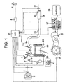
- Fig. 1 is an illustration indicating a composition of an exhaust gas-purifying system of an intake port injection type internal combustion engine which is a typical embodiment of the present invention.
- Fig. 2 is an illustration indicating a composition of an exhaust gas-purifying system of an cylinder injection type internal combustion engine (a direct injection engine) which is a typical embodiment of the present invention.
- Fig. 3 is an illustration indicating a composition of an exhaust gas-purifying system of an internal combustion engine in a simplified hybrid type electric vehicle in the present invention.
- Fig. 4 is an illustration indicating a composition of an exhaust gas-purifying system of an internal combustion engine in a hybrid type electric vehicle in the present invention.
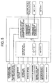
- Fig. 5 is a block diagram indicating a control method of an air-fuel ratio at a NOx reactivation treatment time.
- Fig. 6 is a block diagram indicating a control method at a sulfur-poisoning renewal treatment time.
- Fig. 7 shows properties of a NOx purifying ratio when a rich operation and a lean operation are alternately repeated in the present invention.
- Fig. 8 is a graph for explaining a relation between the accumulated mileage of a vehicle and the NOx purifying ratio.
- Fig. 9 is an illustration for explaining the sulfur-poisoning renewal treatment by the method of the present invention.
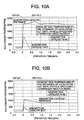
- Figs. 10A and 10B are graphs for explaining a relation between a NOx concentration at an adsorption catalyst entrance and a NOx concentration at an adsorption catalyst exit when a rich (stoichiometric) operation is shifted to a lean operation.
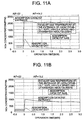
- Figs. 11A and 11B are graphs for explaining a relation between a NOx concentration at an adsorption catalyst entrance and a NOx concentration at an adsorption catalyst exit when a rich (stoichiometric) operation is shifted to a lean operation.
- Fig. 12 is a flow chart for indicating the control method of NOx reactivation treatment.
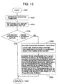
- Fig. 13 is a flow chart for indicating the control method of sulfur-poisoning renewal treatment.
- the first feature of the present invention is as follows.
- the combustion condition of the internal combustion engine is controlled at the stoichiometric air-fuel ratio or an excess fuel air-fuel ratio in a predetermined time period to reactivate the NOx adsorption catalyst from the time-elapsing deterioration.
- the increased proportion of the engine output generated during the above time period is absorbed with the generator.
- the second feature of the present invention is as follows.
- the combustion condition of the internal combustion engine is controlled at the stoichiometric air-fuel ratio or an excess fuel air-fuel ratio in a predetermined time period, and the increased proportion of the engine output generated during the above time period is absorbed with the motor utilized for driving a vehicle or the generator.
- the combustion condition is controlled at the stoichiometric air-fuel ratio or an excess fuel air-fuel ratio.
- the motor for driving a vehicle may utilize electric power of the increased proportion of the generated energy.
- the NOx adsorption catalyst absorbs sulfur contained in the exhaust gas exhausted from the internal combustion engine in place of NOx so that its NOx adsorption or absorption capability decreases.
- the adjustment of a combustion condition in the internal combustion engine to the stoichiometric air-fuel ratio or an excess fuel air-fuel ratio, an increase in an intake air flow rate to the engine, or the retardation of an ignition timing can remove the absorbed sulfur from the NOx adsorption catalyst. When the sulfur is removed, the NOx adsorption capability is reactivated.
- the increased proportion of the engine output torque during the above sulfur-removing-treatment is absorbed by converting the increased output into electric energy by the generator similarly to above or increasing the regeneration braking of the drive motor of the hybrid type electric vehicle, whereby the deterioration of fuel economy can be prevented.
- the timing for accomplishing a state where the amount of a reducer for reducing NOx to N 2 is at least equivalent to that of an oxidizer is as follows.
- the period of time for maintaining the state where the amount of a reducer for reducing NOx to N 2 is equivalent to, or larger than, that of an oxidizer or the amount of a reducer to be added for maintaining the above state can be decided in advance in consideration with properties of the adsorption catalyst and characteristics and properties of the internal combustion engine. These can be accomplished by controlling strokes of a fuel injection valve, an injection time, and an injection interval.
- any one of the following methods may decide the timing for a treatment for recovering the time-elapsing deterioration of the NOx adsorption catalyst (sulfur-removing-treatment).
- the degree of time-elapsing deterioration (for example, the absorption amount of sulfur) is estimated from an air-fuel ratio setting signal, an engine speed signal, an intake air flow rate signal, an intake manifold pressure signal, a vehicle speed signal, a throttle opening, an exhaust gas temperature, an exhaust gas sensor signal, an accumulated mileage and the like, which are decided by ECU (Engine Control Unit).
- ECU Engine Control Unit
- a method for estimating the degree of time-elapsing deterioration is as follows.
- the NOx absorption or adsorption capability is obtained by signals of an exhaust sensor located at downstream of the NOx adsorption catalyst. When the above capability falls below a predetermined value, it is judged that the treatment of NOx catalyst is necessary.
- the NOx purifying ratio gradually decreases in the lean operation, and the purifying ratio, which is 100% initially, comes to about 40% after 20 minutes.
- the above decreased purifying ratio is renewed to 100% by the rich operation for 30 seconds.
- the NOx purifying capability is renewed and the above time-elapsing deterioration is repeated.
- the vehicle speed was kept at a constant speed of about 40 km/h (the spatial velocity (SV) of exhaust gas was a constant velocity of about 20,000/h), and a relationship between the travel distance of the vehicle and the NOx purifying ratio in the lean exhaust gas was determined to obtain Fig. 8.
- the NOx purifying ratio decreases with time, while the decreasing speed thereof tends to quicken with increasing the accumulated mileage. It is supposed that a sulfur content contained in the exhaust gas is bonded to a NOx adsorption or absorption agent to decrease the adsorption capability of the agent, which causes the above tendency.
- the above treatment for the time-elapsing deterioration recovers the NOx adsorption or absorption capability of the catalyst.
- the increased proportion of engine output torque generated during the treatment is converted into electric energy by increasing the load on the generator (generated energy).
- Figs. 10A, 10B, 11A and 11B show NOx purifying characteristics before and after switching the lean operation to the stoichiometric or rich operation.
- Figs. 10A and 10B show NOx concentrations measured at the entrance and exit of the adsorption catalyst N-N9.
- the entrance NOx concentration in the rich operation largely increases.
- the exit NOx concentration increases transiently.
- the exit NOx concentration largely underperforms the entrance NOx concentration. The reactivation advances promptly, and the exit NOx concentration reaches to about zero in a short time.
- the exit NOx concentration constantly largely underperforms the entrance NOx concentration, and the exit NOx concentration reaches to about zero in a shorter time.
- the A/F value as a reactivation condition exerts an influence upon the time required for the reactivation.
- the A/F value, the time and the amount of reducer which are suitable for the reactivation are influenced by the composition and form of an adsorption catalyst, temperature a SV value, the kind of a reducer, and the form and length of an exhaust gas passage. Therefore, the reactivation condition is comprehensively decided in consideration of these requirements.
- Figs. 11A and 11B show NOx concentrations measured at the entrance and exit of an adsorption catalyst N-K9 (a prototype code).
- the exhaust gas purifying system consists of an intake system comprising a lean-burn-capable internal combustion engine 99, air flow sensor 2, throttle valve 3 and the like, an exhaust system comprising an oxygen concentration sensor (or a A/F sensor) 19, an exhaust temperature sensor 22, a NOx adsorption catalyst 18 and the like, and a control unit (ECU) 25.
- an intake system comprising a lean-burn-capable internal combustion engine 99, air flow sensor 2, throttle valve 3 and the like
- an exhaust system comprising an oxygen concentration sensor (or a A/F sensor) 19, an exhaust temperature sensor 22, a NOx adsorption catalyst 18 and the like
- ECU control unit
- the ECU 25 decides an air-fuel ratio (A/F) from these signals, and then, the signal of the air-fuel ratio is corrected on the basis of signals fed back from the oxygen sensor to determine an amount of fuel injection.
- A/F air-fuel ratio
- the ECU 25 has I/O LSI as an input/output interface, a microprocessor unit MPU, storage devices (RAM, ROM and the like) which stores several control programs, and a timer counter.
- the above exhaust gas purifying system performs operations to be explained in outline hereinafter.
- intake air to the engine is filtered with an air cleaner 1, measured for its amount with the air flow sensor 2, passed through the throttle valve 3, mixed with fuel injected from the injector 5, and fed to the engine 99.
- Signals from the air flow sensor and signals from other sensors are input into the ECU 25.
- the operation condition of the engine and the condition of the NOx adsorption catalyst are evaluated by a method to be described later to determine an operation air-fuel ratio, and an injection time of the injector 5 or the like is controlled to set the fuel concentration of an air-fuel mixture at a predetermined value.
- the air-fuel mixture inhaled to a cylinder is ignited with an ignition plug 6 which is controlled with signals from the ECU 25 and burnt, and then the combustion exhaust gas is led to an exhaust purification system.
- the exhaust purification system is provided with the NOx adsorption catalyst 18.
- NOx adsorption catalyst 18 In the stoichiometric operation, its three-way catalyst function purifies or deoxidizes NOx and oxidizes HC and CO in the exhaust gas. Further, in the lean operation, its NOx adsorption function purifies NOx, and concurrently its combustion function burns and oxidizes HC and CO.
- the NOx purifying capability of the NOx adsorption catalyst is constantly judged by judgements and control signals of the ECU.
- the NOx purifying capability is decreased, the air-fuel ratio of combustion is shifted to a rich side and the NOx adsorption capability of the adsorption catalyst is reactivated.
- the output of a generator 51 is increased with a generated energy adjusting unit 52 by means of a command from the ECU 25 for absorbing (recovering) the above increased proportion of the output and the addition of the output from the generator 51 is charged into a battery 38.
- the above addition of the generated energy is used later operation so that fuel economy is improved as a whole. For example, an energy to be generated in an operation to follow is decreased in an amount corresponding to the creased proportion of the generated energy, whereby the load on the engine may be decreased.
- Fig. 2 shows an example of an engine in which a cylinder is equipped with the fuel injection valve 5 differently from Fig. 1 and fuel is directly fed to the cylinder.
- an electric power corresponding to the increased proportion of the generated energy of the generator 31 is used for the motor for driving a vehicle, or the regeneration braking of the drive motor is increased, whereby the above electric power is used for charging the battery.
- the NOx adsorption catalyst absorbs sulfur contained in the exhaust gas from the engine in place of NOx, so that its NOx adsorption or absorption capability is decreased.
- the control of the combustion condition in the engine to the stoichiometric air-fuel ratio or an excess fuel air-fuel ratio, an increase in the intake air flow rate to the engine, or the adjustment of an ignition timing or an fuel injection timing can remove the absorbed sulfur from the NOx adsorption catalyst. When the sulfur is removed, the NOx adsorption capability is recovered.
- the increased proportion of the engine output during the above sulfur-removing-treatment is absorbed (recovered) by increasing the generation energy of the generators 51 and 31 similarly to above description or increasing the regeneration braking of the drive motor of a hybrid type electric vehicle, whereby deterioration in fuel economy can be prevented.
- the present system effectively purifies the exhaust gas under all the engine combustion conditions of the lean operation and the stoichiometric (including rich operation) operation.
- Fig. 3 shows an example of a simplified hybrid type electric vehicle.
- the engine is equipped with a motor/generator 31 comprising functions of a motor for starting an engine and a generator, the NOx adsorption catalyst 18 is provided in the exhaust system, and the increased proportion of the generated energy is recovered through an inverter 48 and a charging and discharging device 49.
- the controls of these are optically carried out with a HEV control unit 42, a battery control unit 41 and an inverter control unit 40. Further, 36 is a differential gear system, and 37 are wheels.
- the HEV control unit 42 is a Hybrid Electric Vehicle control unit which includes a microcomputer, memory devices and an input/output signal interface unit. The HEV control unit 42 controls and manages the operation of the hybrid vehicle so as to optimize the fuel economy, driveability and charging/discharging of the battery system.
- Fig. 4 shows an example of the hybrid type electric vehicle, in which the engine is equipped with the generator 31, and the drive motor 33 is provided between a mechanical-belt type continuously variable transmission CVT 35 and the generator 31 through electro-magnetic clutches 32 and 34.
- the charging and discharging of the battery are respectively optimally performed with the battery control unit 41, the engine control unit 25, the inverter control unit 40, and the HEV control unit 42.
- the block diagram shows a method of controlling the air-fuel ratio of an air-fuel mixture fed to the engine for reducing the adsorbed NOx.
- the ECU 25 determines an air-fuel ratio (A/F) from information such as a load sensor 8 output for outputting a signal responsive to pressing of an accelerator pedal 1, an output signal of intake air flow rate measured with the air flow sensor 2, an engine speed signal detected with the crank angle sensor 29, an exhaust gas temperature signal, a throttle sensor signal for detecting a throttle opening, an engine coolant temperature signal, a starter signal, and a vehicle speed. Further, the signal of the air-fuel ratio is corrected on the basis of a signal fed back from the oxygen sensor 19 to determine an amount of fuel to be injected.
- A/F air-fuel ratio
- a known learning mechanism of air-fuel ratio correction responds so as rightly to respond to a delicate change or an abrupt change of the air-fuel ratio.
- a command from the ECU decides an injection condition of the injector and the stoichiometric and rich operation is performed.
- the presence or absence of the NOx adsorption capability of the NOx adsorption catalyst is judged.
- the fuel injection amount is decided so as to perform a lean operation as prescribed.
- the air-fuel ratio is shifted to a rich side in a predetermined time to reactivate the NOx adsorption catalyst.
- the block diagram in Fig. 6 shows the air-fuel ratio of an air-fuel mixture fed to the engine for removing the adsorbed sulfur from the Nox adsorption catalyst.
- the ECU 25 estimates the amount of the absorbed sulfur, which is adsorbed with the NOx adsorption catalyst, from information such as a load sensor output for outputting a signal responsive to pressing of an accelerator pedal, an output signal of intake air flow rate measured with the air flow sensor 2, an engine speed signal detected with the crank angle sensor, an exhaust gas temperature signal, a throttle sensor signal for detecting the opening of a throttle, an engine coolant temperature signal, a starter signal, and a vehicle speed.
- the air-fuel ratio is shifted to a rich side or the intake air flow rate is increased for a sulfur-poisoning renewal treatment.
- the ignition timing is retarded to increase the exhaust temperature. Owing to this, the sulfur is removed from the NOx adsorption catalyst, and its function is recovered.
- the amount of the absorbed sulfur is estimated as follows.
- Fig. 12 shows a flow chart of an air-fuel ratio control for reducing the adsorbed NOx.
- step 1002 After starting in step 1002, various operation conditions are instructed or signals to detect an operating condition are read in step 1002.
- step 1003 the air-fuel ratio is determined on the basis of these signals .
- step 1004 the determined air-fuel ratio is obtained.
- step 1005 the determined air-fuel ratio of stop 1003 is compared with the stoichiometric air-fuel ratio.
- the stoichiometric air-fuel ratio which is a comparative target is an air-fuel ratio in which the speed of catalytic reduction of NOx in the adsorption catalyst exceeds a capturing speed due to the adsorption, and it is decided by precedently evaluating properties of the adsorption catalyst. An air-fuel ratio near the stoichiometric air-fuel ratio is selected.
- step 1006 in which no reactivation treatment of the adsorption catalyst is carried out and an operation is performed in a prescribed air-fuel ratio.
- step 1007 an estimation operation of NOx adsorbed amount is carried out.
- step 1008 it is judged whether the estimated NOx adsorbed amount is smaller than or equal to a predetermined limit or not.
- the NOx adsorption catalyst is evaluated for NOx capturing characteristic data by an experiment in advance, the exhaust gas temperature, the temperature of the adsorption catalyst and the like are taken into account, and the limit adsorption amount is set at a value sufficient for purifying NOx contained in the exhaust gas.
- step 1006 advance to step 1006 in which no reactivation treatment of the adsorption catalyst is carried out and an operation is performed in a prescribed air-fuel ratio.
- step 1009 in which the air-fuel ratio is shifted to a rich side, and concurrently the generation energy of the generators 31 and 51 is increased in an amount counterbalancing a torque-increased proportion due to the rich operation or the regeneration braking of the drive motor of a hybrid type electric vehicle is increased.
- step 1010 a rich shift time is counted, and when an elapsed time Tr exceeds a predetermined time (Tr)c, the rich shift is terminated.
- Fig. 13 shows a flow chart of the sulfur-poisoning renewal treatment.
- step 1021 various operating conditions are instructed or signals to detect an operating condition are read.
- step 1023 the sulfur absorption amount is estimated on the basis of these signals.
- step 1024 a determined air-fuel ratio is detected, and the absorption amount calculated in step 1023 is compared with a predetermined value.
- step 1027 In the case of the sulfur absorption amount ⁇ the predetermined value, advance to step 1027 in which an operation is performed in a prescribed air-fuel ratio without any sulfur-poisoning renewal treatment.
- step 1025 the air-fuel ratio is shifted to a rich side or the intake air flow rate is increased for the sulfur-poisoning renewal treatment in a predetermined period of time (20 minutes, time period required for removing sulfur) .
- the exhaust gas temperature is increased by an ignition retardation together with the above countermeasures.
- step 1026 the generated energy of the generators 31 and 51 is increased in an amount counterbalancing a torque(output)-increased proportion due to the rich operation or the regeneration braking of the drive motor of a hybrid type electric vehicle is increased.
- the speed ratio of the transmission CVT 35 may be adjusted as required so as not to change the number of revolutions of the final driving wheel of a vehicle.
- a generator with which an engine is equipped can recover the increased proportion of an engine torque (output) generated at a reactivation treatment time of NOx adsorbed to a NOx adsorption catalyst and at a renewal treatment time of a sulfur-poisoning causing the deterioration of a catalyst. Therefore, deterioration in fuel economy can be prevented at the reactivation treatment.
Landscapes
- Engineering & Computer Science (AREA)
- Chemical & Material Sciences (AREA)
- Combustion & Propulsion (AREA)
- Mechanical Engineering (AREA)
- Transportation (AREA)
- General Engineering & Computer Science (AREA)
- Chemical Kinetics & Catalysis (AREA)
- Health & Medical Sciences (AREA)
- Biomedical Technology (AREA)
- Environmental & Geological Engineering (AREA)
- Analytical Chemistry (AREA)
- General Chemical & Material Sciences (AREA)
- Oil, Petroleum & Natural Gas (AREA)
- Automation & Control Theory (AREA)
- Toxicology (AREA)
- Exhaust Gas After Treatment (AREA)
- Hybrid Electric Vehicles (AREA)
- Electrical Control Of Ignition Timing (AREA)
- Control Of Vehicle Engines Or Engines For Specific Uses (AREA)
- Electrical Control Of Air Or Fuel Supplied To Internal-Combustion Engine (AREA)
- Combined Controls Of Internal Combustion Engines (AREA)
- Exhaust Gas Treatment By Means Of Catalyst (AREA)
Applications Claiming Priority (2)
| Application Number | Priority Date | Filing Date | Title |
|---|---|---|---|
| JP2000056044A JP2001241341A (ja) | 2000-02-28 | 2000-02-28 | 内燃機関の排気ガス浄化装置及び浄化方法 |
| JP2000056044 | 2000-02-28 |
Publications (3)
| Publication Number | Publication Date |
|---|---|
| EP1128041A2 true EP1128041A2 (fr) | 2001-08-29 |
| EP1128041A3 EP1128041A3 (fr) | 2002-05-02 |
| EP1128041B1 EP1128041B1 (fr) | 2006-04-26 |
Family
ID=18577070
Family Applications (1)
| Application Number | Title | Priority Date | Filing Date |
|---|---|---|---|
| EP00118230A Expired - Lifetime EP1128041B1 (fr) | 2000-02-28 | 2000-09-01 | Appareil et procédé de purification des émissions de gaz d'échappement pour un moteur à combustion interne |
Country Status (5)
| Country | Link |
|---|---|
| US (1) | US6434928B1 (fr) |
| EP (1) | EP1128041B1 (fr) |
| JP (1) | JP2001241341A (fr) |
| KR (1) | KR100652109B1 (fr) |
| DE (1) | DE60027535T2 (fr) |
Cited By (3)
| Publication number | Priority date | Publication date | Assignee | Title |
|---|---|---|---|---|
| FR2861424A1 (fr) * | 2003-10-28 | 2005-04-29 | Toyota Motor Co Ltd | Dispositif de purification des gaz d'echappement d'un moteur a combustion interne |
| WO2006072499A3 (fr) * | 2004-12-29 | 2006-11-16 | Bosch Gmbh Robert | Procede pour reduire les emissions d'un vehicule automobile en influant sur la puissance de l'alternateur |
| CN100999214B (zh) * | 2006-01-13 | 2010-12-15 | 丰田自动车株式会社 | 混合动力车辆和用于控制混合动力车辆的方法 |
Families Citing this family (32)
| Publication number | Priority date | Publication date | Assignee | Title |
|---|---|---|---|---|
| US6657315B1 (en) * | 2000-08-25 | 2003-12-02 | Ford Global Technologies, Llc | Method of operating a hybrid electric vehicle to reduce emissions |
| US6866610B2 (en) * | 2001-03-30 | 2005-03-15 | Toyota Jidosha Kabushiki Kaisha | Control apparatus and method for vehicle having internal combustion engine and continuously variable transmission, and control apparatus and method for internal combustion engine |
| JP3815256B2 (ja) * | 2001-05-29 | 2006-08-30 | トヨタ自動車株式会社 | 車輌用間歇運転内燃機関のNOx排出抑制運転方法 |
| JP4453235B2 (ja) * | 2001-09-11 | 2010-04-21 | トヨタ自動車株式会社 | 内燃機関の排気浄化装置 |
| JP2003148198A (ja) * | 2001-11-13 | 2003-05-21 | Toyota Motor Corp | 内燃機関の排気浄化装置 |
| JP3700715B2 (ja) * | 2003-08-12 | 2005-09-28 | トヨタ自動車株式会社 | 内燃機関の制御装置 |
| US6925796B2 (en) * | 2003-11-19 | 2005-08-09 | Ford Global Technologies, Llc | Diagnosis of a urea SCR catalytic system |
| BRPI0511863A (pt) * | 2004-06-08 | 2008-01-15 | Cummins Inc | método para modificar o nìvel de disparo para regeneração de adsorvente |
| US7621120B2 (en) * | 2005-06-15 | 2009-11-24 | Southwest Research Institute | Hybrid technology for lean NOx trap and particulate filter regeneration control |
| US7469533B2 (en) * | 2006-04-27 | 2008-12-30 | Ford Global Technologies, Llc | Brake torque load generation process for diesel particulate filter regeneration and SOx removal from lean NOx trap |
| JP2008007004A (ja) * | 2006-06-30 | 2008-01-17 | Fuji Heavy Ind Ltd | ハイブリッド車両の制御装置 |
| JP4100440B2 (ja) * | 2006-09-26 | 2008-06-11 | トヨタ自動車株式会社 | ハイブリッド車両の制御装置 |
| US20080078166A1 (en) * | 2006-09-29 | 2008-04-03 | Charles Rose | Hybrid engine exhaust gas temperature control system |
| US7707826B2 (en) * | 2006-11-07 | 2010-05-04 | Cummins, Inc. | System for controlling triggering of adsorber regeneration |
| US7654079B2 (en) * | 2006-11-07 | 2010-02-02 | Cummins, Inc. | Diesel oxidation catalyst filter heating system |
| US7594392B2 (en) * | 2006-11-07 | 2009-09-29 | Cummins, Inc. | System for controlling adsorber regeneration |
| US7654076B2 (en) * | 2006-11-07 | 2010-02-02 | Cummins, Inc. | System for controlling absorber regeneration |
| US7533523B2 (en) * | 2006-11-07 | 2009-05-19 | Cummins, Inc. | Optimized desulfation trigger control for an adsorber |
| WO2008095752A1 (fr) * | 2007-02-06 | 2008-08-14 | Emitec Gesellschaft Für Emissionstechnologie | Procédé de fonctionnement d'un véhicule à moteur comprenant un dispositif de chauffage de gaz d'échappement |
| US20090033095A1 (en) * | 2007-08-01 | 2009-02-05 | Deepak Aswani | Regenerating an engine exhaust gas particulate filter in a hybrid electric vehicle |
| DE102008010103A1 (de) * | 2008-02-20 | 2009-08-27 | Robert Bosch Gmbh | Verfahren und Vorrichtung zur Ansteuerung eines Antriebstrangs eines Fahrzeugs |
| JP2009275631A (ja) * | 2008-05-15 | 2009-11-26 | Toyota Motor Corp | 車両の制御装置および制御方法 |
| US8535200B2 (en) * | 2009-03-17 | 2013-09-17 | General Electric Company | Vehicle propulsion system having a continuously variable transmission and method of making same |
| US20100240491A1 (en) * | 2009-03-17 | 2010-09-23 | Parag Vyas | System for vehicle propulsion having and method of making same |
| US8549838B2 (en) | 2010-10-19 | 2013-10-08 | Cummins Inc. | System, method, and apparatus for enhancing aftertreatment regeneration in a hybrid power system |
| US8742701B2 (en) | 2010-12-20 | 2014-06-03 | Cummins Inc. | System, method, and apparatus for integrated hybrid power system thermal management |
| EP2722502A4 (fr) * | 2011-06-14 | 2015-06-17 | Hitachi Construction Machinery | Machine de construction |
| US9610938B2 (en) * | 2013-06-24 | 2017-04-04 | Toyota Jidosha Kabushiki Kaisha | Control apparatus for hybrid vehicle |
| JP2015110918A (ja) * | 2013-12-06 | 2015-06-18 | いすゞ自動車株式会社 | 車両の充電方法、充電システム、及び車両 |
| US10030594B2 (en) * | 2015-09-18 | 2018-07-24 | Dana Limited | Abuse mode torque limiting control method for a ball-type continuously variable transmission |
| JP7190048B2 (ja) * | 2019-08-02 | 2022-12-14 | 日産自動車株式会社 | 内燃機関の制御方法及び内燃機関の制御装置 |
| CN112983610B (zh) * | 2019-12-12 | 2022-10-25 | 北京车和家信息技术有限公司 | 催化器的检测方法及混合动力车辆 |
Citations (4)
| Publication number | Priority date | Publication date | Assignee | Title |
|---|---|---|---|---|
| WO1993007363A1 (fr) | 1991-10-03 | 1993-04-15 | Toyota Jidosha Kabushiki Kaisha | Dispositif pour purifier les gaz d'echappement d'un moteur a combustion interne |
| WO1993008383A1 (fr) | 1991-10-14 | 1993-04-29 | Toyota Jidosha Kabushiki Kaisha | Dispositif d'echappement et d'epuration pour moteurs a combustion interne |
| JPH09317447A (ja) | 1996-05-31 | 1997-12-09 | Toyota Motor Corp | 内燃機関の排気浄化装置 |
| JPH1162653A (ja) | 1997-08-25 | 1999-03-05 | Honda Motor Co Ltd | ハイブリッド車両におけるトルクショック軽減装置 |
Family Cites Families (11)
| Publication number | Priority date | Publication date | Assignee | Title |
|---|---|---|---|---|
| JP2827568B2 (ja) * | 1991-04-30 | 1998-11-25 | トヨタ自動車株式会社 | ハイブリッド車の駆動装置 |
| AU666187B2 (en) * | 1992-05-15 | 1996-02-01 | Mitsubishi Jidosha Kogyo Kabushiki Kaisha | Operating method for a hybrid car |
| DE4217668C1 (de) * | 1992-05-28 | 1993-05-06 | Daimler Benz Ag | Verfahren zur Steuerung eines ein Fahrzeug antreibenden Hybridantriebes |
| DE69420488T2 (de) * | 1993-01-19 | 2000-04-13 | Toyota Jidosha K.K., Toyota | Abgasreinigungsgerät für eine brennkraftmaschine |
| US5704339A (en) * | 1996-04-26 | 1998-01-06 | Ford Global Technologies, Inc. | method and apparatus for improving vehicle fuel economy |
| US6212880B1 (en) | 1996-09-20 | 2001-04-10 | Hitachi, Ltd. | Engine control device |
| US5771685A (en) * | 1996-10-16 | 1998-06-30 | Ford Global Technologies, Inc. | Method for monitoring the performance of a NOx trap |
| DE19706608A1 (de) | 1997-02-20 | 1998-08-27 | Ford Global Tech Inc | Verfahren zur Entschwefelung einer Stickoxidfalle im Abgassystem eines Verbrennungsmotors |
| JP3067685B2 (ja) * | 1997-03-31 | 2000-07-17 | 三菱自動車工業株式会社 | 火花点火式筒内噴射型内燃機関の排気浄化装置 |
| JP3334597B2 (ja) * | 1998-03-17 | 2002-10-15 | トヨタ自動車株式会社 | 圧縮着火式内燃機関 |
| FR2784626B1 (fr) * | 1998-10-16 | 2000-12-15 | Renault | Groupe motopropulseur hybride |
-
2000
- 2000-02-28 JP JP2000056044A patent/JP2001241341A/ja active Pending
- 2000-09-01 DE DE60027535T patent/DE60027535T2/de not_active Expired - Fee Related
- 2000-09-01 EP EP00118230A patent/EP1128041B1/fr not_active Expired - Lifetime
- 2000-09-01 US US09/653,166 patent/US6434928B1/en not_active Expired - Fee Related
- 2000-09-04 KR KR1020000051920A patent/KR100652109B1/ko not_active Expired - Fee Related
Patent Citations (4)
| Publication number | Priority date | Publication date | Assignee | Title |
|---|---|---|---|---|
| WO1993007363A1 (fr) | 1991-10-03 | 1993-04-15 | Toyota Jidosha Kabushiki Kaisha | Dispositif pour purifier les gaz d'echappement d'un moteur a combustion interne |
| WO1993008383A1 (fr) | 1991-10-14 | 1993-04-29 | Toyota Jidosha Kabushiki Kaisha | Dispositif d'echappement et d'epuration pour moteurs a combustion interne |
| JPH09317447A (ja) | 1996-05-31 | 1997-12-09 | Toyota Motor Corp | 内燃機関の排気浄化装置 |
| JPH1162653A (ja) | 1997-08-25 | 1999-03-05 | Honda Motor Co Ltd | ハイブリッド車両におけるトルクショック軽減装置 |
Cited By (3)
| Publication number | Priority date | Publication date | Assignee | Title |
|---|---|---|---|---|
| FR2861424A1 (fr) * | 2003-10-28 | 2005-04-29 | Toyota Motor Co Ltd | Dispositif de purification des gaz d'echappement d'un moteur a combustion interne |
| WO2006072499A3 (fr) * | 2004-12-29 | 2006-11-16 | Bosch Gmbh Robert | Procede pour reduire les emissions d'un vehicule automobile en influant sur la puissance de l'alternateur |
| CN100999214B (zh) * | 2006-01-13 | 2010-12-15 | 丰田自动车株式会社 | 混合动力车辆和用于控制混合动力车辆的方法 |
Also Published As
| Publication number | Publication date |
|---|---|
| DE60027535T2 (de) | 2006-09-28 |
| KR20010085215A (ko) | 2001-09-07 |
| EP1128041A3 (fr) | 2002-05-02 |
| EP1128041B1 (fr) | 2006-04-26 |
| JP2001241341A (ja) | 2001-09-07 |
| DE60027535D1 (de) | 2006-06-01 |
| KR100652109B1 (ko) | 2006-11-30 |
| US6434928B1 (en) | 2002-08-20 |
Similar Documents
| Publication | Publication Date | Title |
|---|---|---|
| US6434928B1 (en) | Apparatus and method of purification of exhaust emission of internal combustion engine | |
| EP1247968B1 (fr) | Appareil et méthode de commande d'un véhicule à transmission à variation continue et de son moteur à combustion interne | |
| EP0950804B1 (fr) | Dispositif pour la purification de gaz d'échappement d'un moteur à combustion interne | |
| EP0859132B1 (fr) | Appareil de regulation des emissions de l'echappement pour un moteur a combustion interne | |
| CA2324580C (fr) | Systeme de commande pour vehicule hybride | |
| EP0911499B1 (fr) | Dispositif de purification de gaz d'échappement pour un moteur | |
| KR20030022707A (ko) | 내연기관의 배기 정화 장치 및 그 제어방법 | |
| JP4907026B2 (ja) | Nox貯蔵触媒の再生の必要性を決定するための装置及び方法 | |
| JP3613083B2 (ja) | 排気浄化制御装置 | |
| JP2000008837A (ja) | 内燃機関の排気ガス浄化装置 | |
| CN1376234A (zh) | 位于内燃机排气管内的NOx蓄气催化器损坏状态的诊断方法 | |
| JP2019048580A (ja) | ハイブリッド車両の制御方法及びハイブリッド車両の制御装置 | |
| JP3783430B2 (ja) | ハイブリッド車の故障診断装置 | |
| JP2015051743A (ja) | ハイブリッド車両の制御装置 | |
| KR20180129251A (ko) | 마일드 하이브리드 차량의 mhsg 제어 방법 및 장치 | |
| JP4682906B2 (ja) | 内燃機関の制御装置 | |
| JP2010031737A (ja) | 空燃比制御装置及びハイブリッド車両 | |
| JP4001094B2 (ja) | ハイブリッド車両の制御装置 | |
| JP3897000B2 (ja) | ハイブリッド車両の制御装置 | |
| JPH10212984A (ja) | ハイブリッド自動車用エンジンの燃焼制御装置 | |
| JP4001095B2 (ja) | ハイブリッド車両の制御装置 | |
| US12612032B2 (en) | Control method of air fuel ratio for hybrid vehicle and control device of air fuel ratio for hybrid vehicle | |
| JP2004360569A (ja) | 内燃機関の排気浄化制御装置 | |
| JP2026049368A (ja) | ハイブリッド車両 | |
| SE514288C2 (sv) | Anordning och förfarande för svavelregenerering av NOx- adsorberande katalysator |
Legal Events
| Date | Code | Title | Description |
|---|---|---|---|
| PUAI | Public reference made under article 153(3) epc to a published international application that has entered the european phase |
Free format text: ORIGINAL CODE: 0009012 |
|
| AK | Designated contracting states |
Kind code of ref document: A2 Designated state(s): DE FR GB Kind code of ref document: A2 Designated state(s): AT BE CH CY DE DK ES FI FR GB GR IE IT LI LU MC NL PT SE |
|
| AX | Request for extension of the european patent |
Free format text: AL;LT;LV;MK;RO;SI |
|
| PUAL | Search report despatched |
Free format text: ORIGINAL CODE: 0009013 |
|
| AK | Designated contracting states |
Kind code of ref document: A3 Designated state(s): AT BE CH CY DE DK ES FI FR GB GR IE IT LI LU MC NL PT SE |
|
| AX | Request for extension of the european patent |
Free format text: AL;LT;LV;MK;RO;SI |
|
| 17P | Request for examination filed |
Effective date: 20020830 |
|
| AKX | Designation fees paid |
Free format text: DE FR GB |
|
| 17Q | First examination report despatched |
Effective date: 20040818 |
|
| GRAP | Despatch of communication of intention to grant a patent |
Free format text: ORIGINAL CODE: EPIDOSNIGR1 |
|
| GRAS | Grant fee paid |
Free format text: ORIGINAL CODE: EPIDOSNIGR3 |
|
| GRAF | Information related to payment of grant fee modified |
Free format text: ORIGINAL CODE: EPIDOSCIGR3 |
|
| GRAL | Information related to payment of fee for publishing/printing deleted |
Free format text: ORIGINAL CODE: EPIDOSDIGR3 |
|
| GRAS | Grant fee paid |
Free format text: ORIGINAL CODE: EPIDOSNIGR3 |
|
| GRAA | (expected) grant |
Free format text: ORIGINAL CODE: 0009210 |
|
| RIN1 | Information on inventor provided before grant (corrected) |
Inventor name: MANAKA, TOSHIO,C/O HITACHI LTD., INT.PROP.GROUP, |
|
| RAP1 | Party data changed (applicant data changed or rights of an application transferred) |
Owner name: HITACHI, LTD. |
|
| AK | Designated contracting states |
Kind code of ref document: B1 Designated state(s): DE FR GB |
|
| REG | Reference to a national code |
Ref country code: GB Ref legal event code: FG4D |
|
| REF | Corresponds to: |
Ref document number: 60027535 Country of ref document: DE Date of ref document: 20060601 Kind code of ref document: P |
|
| ET | Fr: translation filed | ||
| PLBE | No opposition filed within time limit |
Free format text: ORIGINAL CODE: 0009261 |
|
| STAA | Information on the status of an ep patent application or granted ep patent |
Free format text: STATUS: NO OPPOSITION FILED WITHIN TIME LIMIT |
|
| 26N | No opposition filed |
Effective date: 20070129 |
|
| PGFP | Annual fee paid to national office [announced via postgrant information from national office to epo] |
Ref country code: FR Payment date: 20080814 Year of fee payment: 9 |
|
| PGFP | Annual fee paid to national office [announced via postgrant information from national office to epo] |
Ref country code: GB Payment date: 20080820 Year of fee payment: 9 |
|
| PGFP | Annual fee paid to national office [announced via postgrant information from national office to epo] |
Ref country code: DE Payment date: 20080908 Year of fee payment: 9 |
|
| GBPC | Gb: european patent ceased through non-payment of renewal fee |
Effective date: 20090901 |
|
| REG | Reference to a national code |
Ref country code: FR Ref legal event code: ST Effective date: 20100531 |
|
| PG25 | Lapsed in a contracting state [announced via postgrant information from national office to epo] |
Ref country code: DE Free format text: LAPSE BECAUSE OF NON-PAYMENT OF DUE FEES Effective date: 20100401 Ref country code: FR Free format text: LAPSE BECAUSE OF NON-PAYMENT OF DUE FEES Effective date: 20090930 |
|
| PG25 | Lapsed in a contracting state [announced via postgrant information from national office to epo] |
Ref country code: GB Free format text: LAPSE BECAUSE OF NON-PAYMENT OF DUE FEES Effective date: 20090901 |