EP1128065A2 - Auftrag eines Schmiermittelfilms auf eine Verdichtertaumelscheibe - Google Patents
Auftrag eines Schmiermittelfilms auf eine Verdichtertaumelscheibe Download PDFInfo
- Publication number
- EP1128065A2 EP1128065A2 EP01100511A EP01100511A EP1128065A2 EP 1128065 A2 EP1128065 A2 EP 1128065A2 EP 01100511 A EP01100511 A EP 01100511A EP 01100511 A EP01100511 A EP 01100511A EP 1128065 A2 EP1128065 A2 EP 1128065A2
- Authority
- EP
- European Patent Office
- Prior art keywords
- swash plate
- film
- sheet
- constituent part
- region
- Prior art date
- Legal status (The legal status is an assumption and is not a legal conclusion. Google has not performed a legal analysis and makes no representation as to the accuracy of the status listed.)
- Withdrawn
Links
Images


Classifications
-
- F—MECHANICAL ENGINEERING; LIGHTING; HEATING; WEAPONS; BLASTING
- F04—POSITIVE - DISPLACEMENT MACHINES FOR LIQUIDS; PUMPS FOR LIQUIDS OR ELASTIC FLUIDS
- F04B—POSITIVE-DISPLACEMENT MACHINES FOR LIQUIDS; PUMPS
- F04B27/00—Multi-cylinder pumps specially adapted for elastic fluids and characterised by number or arrangement of cylinders
- F04B27/08—Multi-cylinder pumps specially adapted for elastic fluids and characterised by number or arrangement of cylinders having cylinders coaxial with, or parallel or inclined to, main shaft axis
- F04B27/10—Multi-cylinder pumps specially adapted for elastic fluids and characterised by number or arrangement of cylinders having cylinders coaxial with, or parallel or inclined to, main shaft axis having stationary cylinders
- F04B27/1036—Component parts, details, e.g. sealings, lubrication
- F04B27/1054—Actuating elements
-
- F—MECHANICAL ENGINEERING; LIGHTING; HEATING; WEAPONS; BLASTING
- F05—INDEXING SCHEMES RELATING TO ENGINES OR PUMPS IN VARIOUS SUBCLASSES OF CLASSES F01-F04
- F05C—INDEXING SCHEME RELATING TO MATERIALS, MATERIAL PROPERTIES OR MATERIAL CHARACTERISTICS FOR MACHINES, ENGINES OR PUMPS OTHER THAN NON-POSITIVE-DISPLACEMENT MACHINES OR ENGINES
- F05C2203/00—Non-metallic inorganic materials
- F05C2203/08—Ceramics; Oxides
- F05C2203/0804—Non-oxide ceramics
- F05C2203/0856—Sulfides
- F05C2203/086—Sulfides of molybdenum
-
- F—MECHANICAL ENGINEERING; LIGHTING; HEATING; WEAPONS; BLASTING
- F05—INDEXING SCHEMES RELATING TO ENGINES OR PUMPS IN VARIOUS SUBCLASSES OF CLASSES F01-F04
- F05C—INDEXING SCHEME RELATING TO MATERIALS, MATERIAL PROPERTIES OR MATERIAL CHARACTERISTICS FOR MACHINES, ENGINES OR PUMPS OTHER THAN NON-POSITIVE-DISPLACEMENT MACHINES OR ENGINES
- F05C2253/00—Other material characteristics; Treatment of material
- F05C2253/12—Coating
Definitions
- the present invention relates to a constituent part in a compressor and a method for forming a film on the constituent part in a compressor.
- a coating material is applied on a peripheral surface of a metal roller, and the coating material on the metal roller is transferred on a peripheral surface of a printing roller, which is made of a synthetic rubber, and then the coating material transferred on the peripheral surface of the printing roller is applied to a piston.
- the metal roller contacts the printing roller, and the printing roller contacts the piston to be coated.
- the coating material on the metal roller is adjusted to be predetermined thickness by a comma roller before transferred to the printing roller.
- a coating material prepared on a concave printing plate at a predetermined thickness and in a predetermined shape is transferred to a pad, and the coating material on the pad is printed on the constituent part to be coated.
- a line is formed on a coating film passing between a comma roller and a metal roller when a foreign substance is got into a clearance therebetween. This line is transferred to the film applied on the piston, so the quality of the film is deteriorated. As long as the foreign substance is not removed, the line is formed on every film of a subsequent piston to be filmed.
- a film is creased if the pad is deformed ununiformly.
- a contacting surface of the pad with the constituent part is plane, a film is not satisfactorily formed since air is involved therebetween.
- the contacting surface of the pad is in a convex curved shape so that it prevents air from being involved in, the thickness of the film is not uniform. For the closer to the center of the contacting surface it is, the stronger the contacting force of the pad against the constituent part becomes. Therefore, the film needs to be dried, calcinated, and then polished so that the thickness of it is adjusted.
- the present invention relates to a method for forming a film on a region of the constituent part, and the film is formed by adhering a sheet to form a film to the region so as to fit the shape of the region.
- the present invention has following features.
- the sheet which is fitted to the shape of the region, is formed. Afterward the sheet is adhered to the region, whereby the film is formed.
- the film of a uniform thickness is easily formed.
- the sheet is a resin sheet containing a solid lubricant.
- the resin sheet containing the solid lubricant is effective to form a film so as to improve slidability.
- the present invention relates to the constituent part in the compressor, and the film is formed in the region of the constituent part. According to the present invention, the film of a uniform thickness is easily formed, and adhered to the constituent part in the compressor.
- the compressor is a swash plate type compressor, and the constituent part is the swash plate.
- the swash plate is integrally rotated with a drive shaft. The rotation of the swash plate through the shoes is converted into the reciprocating movement of pistons.
- the region to be filmed is the sliding region of the swash plate to the shoes. The sliding region of the swash plate to the shoes is suitable for the region to be filmed.
- the present invention has following features.
- An adhesive layer is arranged on the region to be filmed, and the sheet is adhered over the region through the adhesive layer.
- the adhesive layer is arranged on the region in advance, it is easy to adhere the sheet to the region.
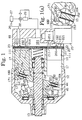
- FIG. 1 An inner construction of a variable displacement compressor is illustrated in Fig. 1.
- a cylinder block 11 is connected to a rear end of a front housing 12 and to a front end of a rear housing 19.
- the cylinder block 11, the front housing 12, and the rear housing 19 constitute a housing assembly.
- a drive shaft 13 is inserted in the front housing 12 and the cylinder block 11 forming a crank chamber 121.
- the drive shaft 13 receives the drive power from the outer driving source such as a vehicle engine.
- a rotary support member 14 is mounted around the drive shaft 13, and a swash plate 15 is supported slidably and inclinably in the axial direction of the drive shaft 13.
- a pair of brackets 151 is integrally formed with the swash plate 15 made of steel, and a pair of guide pins 16 is mounted on the bracket 151.
- the guide pin 16 is slidably inserted into a respective guide hole 141 formed on the rotary support member 14.
- the swash plate 15 is rotated integrally with the drive shaft 13 and inclinably in the axial direction of the drive shaft 13 by the association between the guide hole 141 and the guide pin 16.
- the inclination of the swash plate 15 is guided by the slide guide relation between the guide hole 141 and the guide pin 16, and by a slide support of the drive shaft 13.
- the inclination of the swash plate 15 is adjusted under the pressure control in the crank chamber 121.
- the refrigerant in the crank chamber 121 flows into a suction chamber 191 in a rear housing 19 through a pressure release passage, which is not illustrated.
- the refrigerant in a discharge chamber 192 in the rear housing 19 is supplied into the crank chamber 121 through a pressure supply passage, which is not illustrated.
- a capacity control valve 25 is arranged in the pressure supply passage, and the flow rate of the refrigerant supplied from the discharge chamber 192 to the crank chamber 121 is adjusted by the capacity control valve 25.
- the capacity control valve 25 When the flow rate of the refrigerant increases, the pressure in the crank chamber 121 increases.
- the pressure in the crank chamber 121 decreases. That is, the inclination of the swash plate 15 is adjusted by the capacity control valve 25.
- the abutment between the swash plate 15 and the rotary support member 14 regulates the maximum inclination of the swash plate 15.
- the abutment between a circular clip 24 around the drive shaft 13 and the swash plate 15 regulates the minimum inclination of the swash plate 15.
- a plurality of cylinder bores 111 (only two of the cylinder bores are illustrated in Fig. 1) are arranged around the drive shaft 13 in the cylinder block 11.
- a piston 17 is accommodated in each cylinder bore 111.
- the piston 17 at the upper side is at the top dead center, and the piston 17 at the lower side is at the bottom dead center.
- the rotating movement of the swash plate 15 integrally rotated with the drive shaft 13 is converted into the back-and-forth reciprocating movement of the piston 17 through a pair of semi-spherical shoes 18A and 18B, and the piston 17 moves back and forth in the cylinder bore 111.
- the shoe 18A made of steel slides on one sliding surface 30 of the swash plate 15, and the shoe 18B made of steel slides on another sliding surface 31 of the swash plate 15.
- the suction movement of the piston 17 draws the refrigerant in the suction chamber 191 into the cylinder bore 111 through an intake port 201 of a valve plate 20, pushing away a suction valve 211 of a suction valve plate 21.
- the discharge movement of the piston 17 discharges the refrigerant in the cylinder bore 111 into the discharge chamber 192 through a discharge port 202 of the valve plate 20, pushing away a discharge valve 221 of a discharge valve plate 22.
- a retainer 231 of a retainer plate 23 regulates the opening degree of the discharge valve 221 by the abutment therebetween.
- the discharge chamber 192 and the suction chamber 191 are connected through an external refrigerant circuit 26.
- the refrigerant in the discharge chamber 192 flows outside the compressor, through a condenser 27, an expansion valve 28 and an evaporator 29 in the external refrigerant circuit 26, and returns to the suction chamber 191.
- a connecting portion 171 is formed on the piston 17, and a pair of semi-spherical concave portions 172 and 173 is formed on the connecting portion 171.
- the shoe 18A sliding on one sliding surface 30 of the swash plate 15 is held in the concave portion 172 to be fitted therein, and the shoe 18B sliding on another sliding surface 31 of the swash plate 15 is held in the concave portion 173 to be fitted therein.
- Films 32 and 33 are formed on the end surfaces 152 and 153 which are film formed regions of the sliding surfaces 30, 31 of the swash plate 15.
- the film 32 is adhered to the end surface 152 through an adhesive layer 44
- the film 33 is adhered to the end surface 153 through an adhesive layer 45.
- the surface of the film 32 forms the sliding surface 30, and the surface of the film 33 forms the sliding surface 31.
- the films 32 and 33 are made of thermosetting resin containing solid lubricants such as molybdenum disulfide, tungsten disulfide and graphite.
- the adhesive layers 44 and 45 are made of adhesives of thermosetting resin.
- the films 32 and 33 are formed by the film forming device as shown in Fig. 2.
- a first driving device 35 and a second driving device 36 are mounted on a base frame 34.
- a feeding plate 37 which is horizontally arranged, is reciprocated by the first driving device 35.
- the feeding plate 37 is horizontally reciprocated at a predetermined height.
- the feeding plate 37 is reciprocated between the feeding position shown in Fig. 2 and the preparing position shown in Fig. 3.
- An annular holding slot 371 is recessed on the feeding plate 37.
- a suction device 39 is mounted beneath a support shaft 38 which is vertically and horizontally moved by the second driving device 36.
- the suction device 39 is composed of a blower 40 and a cylindrical hollow body 41, and a plurality of suction bores 412 are arranged in a bottom wall 411 of the hollow body 41 annularly around an axial line 413 of the hollow body 41.
- a seat 42 is arranged on the extended position of the feeding plate 37.
- the swash plate 15 on which films are to be formed is arranged on the seat 42.
- a swash plate 15 is mounted on the seat 42 so that the end surface 152 is upward.
- an annular sheet 43 to form a film is supplied into a holding slot 371.
- the sheet 43 is made of thermosetting resin containing the solid lubricants such as molybdenum disulfide, tungsten disulfide and graphite, and is formed in predetermined thickness in advance.
- the suction device 39 is lowered to the solid line position from the chain line position in Fig. 2.
- the bottom wall 411 of the hollow body 41 is abutted to the feeding plate 37, and then a blower 40 operates.
- the blower 40 generates a suction force at the suction bore 412, and the sheet 43 is absorbed to the bottom wall 411.
- the suction device 39 absorbing the sheet 43 is raised to the chain line position in Fig. 2, and is moved horizontally to the chain line position in Fig. 3.
- the suction device 39 is lowered to the solid line position in Fig. 3, and the end surface 152 of the swash plate 15 is contacted by the sheet 43.
- the blower 40 stops operation.
- the adhesive layer 44 is formed on the end surface 152 of the swash plate 15 in advance.
- the adhesive layer 45 is also formed on the end surface 153 of the swash plate 15.
- the sheet 43 is adhered to the end surface 152 through the adhesive layer 44 by press-contacting to the end surface 152.
- the suction device 39 is moved to the solid line position in Fig. 2 through the chain line positions in Figs. 3 and 2. Then the new sheet 43 on the holding slot 371 is absorbed to the bottom wall 411 of the hollow body 41. The swash plate 15 is turned over so that the end surface 153 is upward. The new sheet 43 absorbed to the bottom wall 411 of the hollow body 41 is adhered to the end surface 153 as well as to the end surface 152.
- a support base plate 46 is mounted beneath the bottom end of a support shaft 38A driven by a second driving device 36A, and a motor 47 is mounted beneath the bottom surface of the support base plate 46.
- An absorption roller 48 in a hollow body is mounted around an output shaft 471 of the motor 47.
- a concave portion 481, whose shape is appropriate to avoid the interference with the swash plate 15, is formed on the peripheral surface of the absorption roller 48. As shown in Fig. 9, when the peripheral surface of the absorption roller 48 is developed, the shape of the concave portion 481 is in a circle larger than a cylindrical base portion 154 of the swash plate 15.
- annular absorbing portion 482 is formed on the peripheral surface of the absorption roller 48.
- a developed plan of the peripheral surface of the absorption roller 48 is shown in Fig. 9.
- the absorbing portion 482 is made of a material having gas permeability.
- the absorbing portion 482 is almost the same in size as the sheet 43 prepared in a holding slot 441 shown in Fig. 8.
- a blower 49 is mounted beneath the bottom surface of the support base plate 46.
- the blower 49 is connected to the output shaft 471, and a suction passage 472 (which is illustrated in Figs. 6 and 7) is formed in the output shaft 471.
- the suction passage 472 connects to the hollow portion of the absorption roller 48. A sucking force is caused on the outer surface of the absorbing portion 482 when the blower 49 operates.
- the absorption roller 48 When the sheet 43 is prepared in the holding slot 441 as shown in Fig. 8 while the feeding plate 37 is at the feeding position as shown in Fig. 4, the absorption roller 48 is arranged at the predetermined height as shown in Fig. 6(a) and a solid line position r 0 as shown in Fig. 8. Then the absorption roller 48 is lowered at the solid line position in Fig. 8, and press-contacts to the feeding plate 37 as shown in Fig. 6(b). The absorption roller 48 moves in the direction of an arrow R1 in Fig. 8 at a certain speed while the absorption roller 48 moves to the position in Fig. 6(c) with rotating in the direction of an arrow Q1 in Fig.
- the absorption roller 48 rotates so as to roll on the feeding plate 37.
- the moving speed of the absorption roller 48 is the same as its peripheral speed, and the absorbing portion 482 contacts the sheet 43 in the holding slot 441 with rolling. Accordingly, the sheet 43 in the annular holding slot 441 is transferred to the peripheral surface of the absorbing portion 482 as it is shown in Fig. 9, and then the motor 47 stops operating.
- the absorption roller 48 absorbing the sheet 43 is raised to the above-mentioned predetermined height from the position in Fig. 6(c). That is, the absorption roller 48 is raised at the chain line position rl in Fig. 8.
- the absorption roller 48 in Fig. 4 denotes this raised position.
- the absorption roller 48 horizontally moves in the direction of an arrow R2 in Fig. 8.
- the absorption roller 48 is arranged at the above-mentioned predetermined height in Fig. 7(a) and at the chain line position r2 in Fig. 8 by the horizontal movement.
- the absorption roller 48 in Fig. 5 denotes the arranged position.
- the absorption roller 48 is lowered at the chain line position r2 in Fig.
- the adhesive layer 44 is adhered to the end surface 152 of the swash plate 15 in advance.
- the absorption roller 48 moves in the direction of an arrow R3 in Fig. 8 at a certain speed while the absorption roller 48 moves to the position in Fig. 7(c) with rotating in the direction of an arrow Q2 in Fig. 7(b) at a certain speed, at the same time the motor 47 operates with maintaining this press-contact.
- the moving speed of the absorption roller 48 is the same as its peripheral speed. Therefore, the absorption roller 48 moves from the position in Fig. 7(b) to the position in Fig.
- the sheet 43 on the peripheral surface of the absorbing portion 482 of the absorption roller 48 is transferred and adhered to the end surface 152 of the swash plate 15, with the shape of the sheet 43 maintained.
- the base portion 154 of the swash plate 15 enters in the concave portion 481, so the base portion 154 does not interfere with the absorption roller 48.
- the absorption roller 48 which adhered the sheet 43 to the swash plate 15, is raised to the above-mentioned predetermined height from the position in Fig. 7(c). That is, the absorption roller 48 is raised at the chain line position r3 in Fig. 8. Next, the absorption roller 48 moves horizontally in the direction of an arrow R4. By the horizontal movement, the absorption roller 48 is arranged at the above-mentioned predetermined height in Fig. 6(a) and at the solid line position r 0 in Fig. 8. When the absorption roller 48 returns to the position in Fig. 6(a), a new sheet 43 is supplied in the holding slot 441 and the holding slot 441 is arranged at the preparing position S in Fig. 4. Then the sheet 43 is absorbed to the absorption roller 48, and the adhesion of the sheet 43 to another end surface 153 of the swash plate 15 or to a new swash plate 15 to be filmed are also performed in turn.
- the film is formed by adhering the sheet to the region so as to fit the shape of the region, so the excellent effect that the film of a high quality is formed on the constituent part in the compressor can be performed.
- the object of the present invention is to form a film of a high quality on a constituent part in a compressor.
- the compressor has a swash plate as a constituent part to be filmed.
- the swash plate on which the film is to be formed is arranged on a seat of a film forming device.
- An adhesive layer is formed to the end surfaces of the swash plate in advance.
- a sheet to form a film is absorbed to a hollow body of a suction device of the film forming device, and press-contacted to the swash plate. The sheet is thus adhered to the end surface of the swash plate.
Landscapes
- Engineering & Computer Science (AREA)
- Mechanical Engineering (AREA)
- General Engineering & Computer Science (AREA)
- Compressors, Vaccum Pumps And Other Relevant Systems (AREA)
- Compressor (AREA)
- Lubricants (AREA)
Applications Claiming Priority (2)
| Application Number | Priority Date | Filing Date | Title |
|---|---|---|---|
| JP2000044715A JP2001234861A (ja) | 2000-02-22 | 2000-02-22 | 圧縮機の皮膜形成対象部品及び皮膜形成対象部品における皮膜形成方法 |
| JP2000044715 | 2000-02-22 |
Publications (2)
| Publication Number | Publication Date |
|---|---|
| EP1128065A2 true EP1128065A2 (de) | 2001-08-29 |
| EP1128065A3 EP1128065A3 (de) | 2003-09-17 |
Family
ID=18567433
Family Applications (1)
| Application Number | Title | Priority Date | Filing Date |
|---|---|---|---|
| EP01100511A Withdrawn EP1128065A3 (de) | 2000-02-22 | 2001-01-09 | Auftrag eines Schmiermittelfilms auf eine Verdichtertaumelscheibe |
Country Status (3)
| Country | Link |
|---|---|
| US (1) | US6487958B2 (de) |
| EP (1) | EP1128065A3 (de) |
| JP (1) | JP2001234861A (de) |
Families Citing this family (1)
| Publication number | Priority date | Publication date | Assignee | Title |
|---|---|---|---|---|
| JP2002089437A (ja) * | 2000-09-13 | 2002-03-27 | Toyota Industries Corp | 圧縮機における潤滑用皮膜形成対象部品 |
Citations (3)
| Publication number | Priority date | Publication date | Assignee | Title |
|---|---|---|---|---|
| JPH10260081A (ja) | 1997-01-31 | 1998-09-29 | Moulinex Sa | 電子レンジ用マグネトロンの温度測定装置 |
| JPH11173263A (ja) | 1997-10-09 | 1999-06-29 | Toyota Autom Loom Works Ltd | 斜板式圧縮機 |
| JPH11193780A (ja) | 1997-12-26 | 1999-07-21 | Toyota Autom Loom Works Ltd | 片頭ピストン型斜板式圧縮機および斜板の製造方法 |
Family Cites Families (4)
| Publication number | Priority date | Publication date | Assignee | Title |
|---|---|---|---|---|
| US3869393A (en) * | 1970-05-21 | 1975-03-04 | Everlube Corp Of America | Solid lubricant adhesive film |
| ID18885A (id) | 1996-07-08 | 1998-05-20 | Toyoda Automatic Loom Works | Piston-piston untuk kompresor serta tata cara dan pesawat untuk melapis piston-pistonnya |
| JP3259215B2 (ja) * | 1996-07-08 | 2002-02-25 | 株式会社豊田自動織機 | 圧縮機のピストン及び同ピストンへのコーティング方法 |
| US6230609B1 (en) * | 1999-06-03 | 2001-05-15 | Norton Performance Plastics Corporation | Fluoropolymer diaphragm with integral attachment device |
-
2000
- 2000-02-22 JP JP2000044715A patent/JP2001234861A/ja not_active Withdrawn
-
2001
- 2001-01-09 EP EP01100511A patent/EP1128065A3/de not_active Withdrawn
- 2001-01-18 US US09/764,559 patent/US6487958B2/en not_active Expired - Fee Related
Patent Citations (3)
| Publication number | Priority date | Publication date | Assignee | Title |
|---|---|---|---|---|
| JPH10260081A (ja) | 1997-01-31 | 1998-09-29 | Moulinex Sa | 電子レンジ用マグネトロンの温度測定装置 |
| JPH11173263A (ja) | 1997-10-09 | 1999-06-29 | Toyota Autom Loom Works Ltd | 斜板式圧縮機 |
| JPH11193780A (ja) | 1997-12-26 | 1999-07-21 | Toyota Autom Loom Works Ltd | 片頭ピストン型斜板式圧縮機および斜板の製造方法 |
Also Published As
| Publication number | Publication date |
|---|---|
| JP2001234861A (ja) | 2001-08-31 |
| US6487958B2 (en) | 2002-12-03 |
| EP1128065A3 (de) | 2003-09-17 |
| US20010017078A1 (en) | 2001-08-30 |
Similar Documents
| Publication | Publication Date | Title |
|---|---|---|
| AU688070B2 (en) | Variable displacement piston type compressor | |
| CN1118625C (zh) | 压缩机的活塞及活塞式压缩机 | |
| KR100249958B1 (ko) | 압축기의 피스톤, 피스톤에의 코팅 형성 방법 및 코팅 형성 장치 | |
| KR100327083B1 (ko) | 사판식 압축기 | |
| US6283012B1 (en) | Compressor piston and method for coating piston | |
| US6487958B2 (en) | Method for forming a film on a constituent part in a compressor | |
| JP2001295757A (ja) | 可変容量圧縮機 | |
| KR100327084B1 (ko) | 사판식 압축기 | |
| JPH09242667A (ja) | 往復動型圧縮機 | |
| US20030025276A1 (en) | Shaft sealing devices, compressors comprising the shaft sealing devices, and methods for sealing a rotational shaft | |
| US20020174764A1 (en) | Swash plate type compressor | |
| US6212995B1 (en) | Variable-displacement inclined plate compressor | |
| EP0995905A2 (de) | Kompressorkolben | |
| JPH10299654A (ja) | ピストン式圧縮機 | |
| EP1136699A2 (de) | Verfahren zum Aufbringen eines Films auf die Taumelscheibe eines Kompressors | |
| JP2003176872A (ja) | 軸封装置及びその組み付け方法 | |
| EP1091121A2 (de) | Filmbeschichteter Kolben | |
| EP1128066A2 (de) | Taumelscheibe mit Beschichtung | |
| JPH10196527A (ja) | 斜板式圧縮機 | |
| JP2941432B2 (ja) | 圧縮機のピストン及びピストン式圧縮機 | |
| EP1188923A2 (de) | Beschichtung einer Schrägscheibe eines Kompressors | |
| JPH11201038A (ja) | 圧縮機のピストン | |
| KR101142767B1 (ko) | 압축기용 피스톤 | |
| JP2001241378A (ja) | 斜板式圧縮機の斜板における皮膜形成方法 | |
| JP2004176652A (ja) | 斜板式圧縮機 |
Legal Events
| Date | Code | Title | Description |
|---|---|---|---|
| PUAI | Public reference made under article 153(3) epc to a published international application that has entered the european phase |
Free format text: ORIGINAL CODE: 0009012 |
|
| 17P | Request for examination filed |
Effective date: 20010109 |
|
| AK | Designated contracting states |
Kind code of ref document: A2 Designated state(s): AT BE CH CY DE DK ES FI FR GB GR IE IT LI LU MC NL PT SE TR |
|
| AX | Request for extension of the european patent |
Free format text: AL;LT;LV;MK;RO;SI |
|
| RAP1 | Party data changed (applicant data changed or rights of an application transferred) |
Owner name: KABUSHIKI KAISHA TOYOTA JIDOSHOKKI |
|
| PUAL | Search report despatched |
Free format text: ORIGINAL CODE: 0009013 |
|
| AK | Designated contracting states |
Kind code of ref document: A3 Designated state(s): AT BE CH CY DE DK ES FI FR GB GR IE IT LI LU MC NL PT SE TR |
|
| AX | Request for extension of the european patent |
Extension state: AL LT LV MK RO SI |
|
| STAA | Information on the status of an ep patent application or granted ep patent |
Free format text: STATUS: THE APPLICATION IS DEEMED TO BE WITHDRAWN |
|
| 18D | Application deemed to be withdrawn |
Effective date: 20030801 |