EP1128066A2 - Taumelscheibe mit Beschichtung - Google Patents
Taumelscheibe mit Beschichtung Download PDFInfo
- Publication number
- EP1128066A2 EP1128066A2 EP01103560A EP01103560A EP1128066A2 EP 1128066 A2 EP1128066 A2 EP 1128066A2 EP 01103560 A EP01103560 A EP 01103560A EP 01103560 A EP01103560 A EP 01103560A EP 1128066 A2 EP1128066 A2 EP 1128066A2
- Authority
- EP
- European Patent Office
- Prior art keywords
- film
- paint
- swash plate
- film forming
- compressor
- Prior art date
- Legal status (The legal status is an assumption and is not a legal conclusion. Google has not performed a legal analysis and makes no representation as to the accuracy of the status listed.)
- Pending
Links
- 239000007888 film coating Substances 0.000 title 1
- 238000009501 film coating Methods 0.000 title 1
- 239000003973 paint Substances 0.000 claims abstract description 93
- 238000000034 method Methods 0.000 claims abstract description 21
- 239000012530 fluid Substances 0.000 claims description 16
- 239000000314 lubricant Substances 0.000 claims description 5
- 239000011347 resin Substances 0.000 claims description 5
- 229920005989 resin Polymers 0.000 claims description 5
- 239000007787 solid Substances 0.000 claims description 5
- 230000007480 spreading Effects 0.000 claims description 2
- 238000003892 spreading Methods 0.000 claims description 2
- 238000005461 lubrication Methods 0.000 abstract description 31
- 230000007246 mechanism Effects 0.000 abstract description 8
- 238000000576 coating method Methods 0.000 description 57
- 239000011248 coating agent Substances 0.000 description 53
- 230000002093 peripheral effect Effects 0.000 description 14
- 239000003507 refrigerant Substances 0.000 description 10
- 229910052751 metal Inorganic materials 0.000 description 7
- 239000002184 metal Substances 0.000 description 7
- XEEYBQQBJWHFJM-UHFFFAOYSA-N Iron Chemical compound [Fe] XEEYBQQBJWHFJM-UHFFFAOYSA-N 0.000 description 6
- 239000002245 particle Substances 0.000 description 6
- 230000008901 benefit Effects 0.000 description 3
- 229910052742 iron Inorganic materials 0.000 description 3
- 239000000463 material Substances 0.000 description 3
- 230000008569 process Effects 0.000 description 2
- OKTJSMMVPCPJKN-UHFFFAOYSA-N Carbon Chemical compound [C] OKTJSMMVPCPJKN-UHFFFAOYSA-N 0.000 description 1
- 230000008859 change Effects 0.000 description 1
- 230000007423 decrease Effects 0.000 description 1
- 238000007598 dipping method Methods 0.000 description 1
- 238000006073 displacement reaction Methods 0.000 description 1
- 238000001035 drying Methods 0.000 description 1
- 229910002804 graphite Inorganic materials 0.000 description 1
- 239000010439 graphite Substances 0.000 description 1
- 230000012447 hatching Effects 0.000 description 1
- 238000012986 modification Methods 0.000 description 1
- 230000004048 modification Effects 0.000 description 1
- CWQXQMHSOZUFJS-UHFFFAOYSA-N molybdenum disulfide Chemical compound S=[Mo]=S CWQXQMHSOZUFJS-UHFFFAOYSA-N 0.000 description 1
- 229910052982 molybdenum disulfide Inorganic materials 0.000 description 1
- 238000002360 preparation method Methods 0.000 description 1
- 238000003825 pressing Methods 0.000 description 1
- 230000001681 protective effect Effects 0.000 description 1
- 239000007921 spray Substances 0.000 description 1
- 229920001187 thermosetting polymer Polymers 0.000 description 1
- ITRNXVSDJBHYNJ-UHFFFAOYSA-N tungsten disulfide Chemical compound S=[W]=S ITRNXVSDJBHYNJ-UHFFFAOYSA-N 0.000 description 1
Images


Classifications
-
- F—MECHANICAL ENGINEERING; LIGHTING; HEATING; WEAPONS; BLASTING
- F04—POSITIVE - DISPLACEMENT MACHINES FOR LIQUIDS; PUMPS FOR LIQUIDS OR ELASTIC FLUIDS
- F04B—POSITIVE-DISPLACEMENT MACHINES FOR LIQUIDS; PUMPS
- F04B27/00—Multi-cylinder pumps specially adapted for elastic fluids and characterised by number or arrangement of cylinders
- F04B27/08—Multi-cylinder pumps specially adapted for elastic fluids and characterised by number or arrangement of cylinders having cylinders coaxial with, or parallel or inclined to, main shaft axis
- F04B27/10—Multi-cylinder pumps specially adapted for elastic fluids and characterised by number or arrangement of cylinders having cylinders coaxial with, or parallel or inclined to, main shaft axis having stationary cylinders
- F04B27/1036—Component parts, details, e.g. sealings, lubrication
- F04B27/1054—Actuating elements
- F04B27/1063—Actuating-element bearing means or driving-axis bearing means
-
- F—MECHANICAL ENGINEERING; LIGHTING; HEATING; WEAPONS; BLASTING
- F05—INDEXING SCHEMES RELATING TO ENGINES OR PUMPS IN VARIOUS SUBCLASSES OF CLASSES F01-F04
- F05C—INDEXING SCHEME RELATING TO MATERIALS, MATERIAL PROPERTIES OR MATERIAL CHARACTERISTICS FOR MACHINES, ENGINES OR PUMPS OTHER THAN NON-POSITIVE-DISPLACEMENT MACHINES OR ENGINES
- F05C2253/00—Other material characteristics; Treatment of material
- F05C2253/12—Coating
Definitions
- the present invention relates to a part of a compressor to be formed with a film and a method of forming the film on the part.
- a method of coating a paint for lubrication on a part, such as the swash plate or the piston of a compressor, to be formed with a film is disclosed in Japanese Unexamined Patent Publications (Kokai) Nos. 10-26081 and 11-173263.
- a paint is attached on the peripheral surface of a metal roller and then transferred to the peripheral surface of a rubber roller, and the paint transferred to the peripheral surface of the rubber roller is coated on the part to be formed with a film.
- the metal roller and the rubber roller are in sliding contact with each other, and so are the rubber roller and the part to be formed with a film.
- the paint attached on the metal roller is reduced to a predetermined thickness by being passed between a comma roller and the metal roller before being transferred to the rubber roller.
- particle if caught in the gap between the comma roller and the metal roller, generates a streak on the paint film that has passed between the comma roller and the metal roller. This streak is transferred also to the film formed by being coated on the part to be formed with a film thereby to deteriorate the quality of the film. Unless the particle is removed, the streak is generated on all the films subsequently formed on the part to be formed with the film.
- the film is liable to be wrinkled by the ununiform deformation of the pad.
- the air may be sealed in and make it impossible to form a satisfactory film.
- the force of pressing the pad against the part to be formed with a film increases toward the center of the particular surface of the pad, thereby making an ununiform film thickness. Therefore, the film must be ground, for adjusting the thickness, after being dried and baked.
- the object of the present invention is to form a film of high quality on a part of the compressor to be formed with the film.
- a film forming method for forming a film by attaching a fluid paint on a film forming area comprising the steps of attaching the fluid paint to the film forming area, and removing by centrifugal force the surplus portion of the fluid paint attached on the film forming area.
- the method for removing the surplus portion of the paint by centrifugal force is effective for securing a uniform film thickness.
- the paint is a resin containing a solid lubricant.
- the resin containing a solid lubricant effectively forms a film for an improved slidability.
- a film forming method comprising further the step of spreading said paint on the flat surface of the film forming area due to the centrifugal force.
- a film forming method described in the aforementioned first or second aspect in which a film is formed on the film forming area of a part of the compressor to be formed with a film.
- the film formed by removing the surplus portion of the paint by centrifugal force has a uniform thickness.
- a film forming method for the compressor of swash plate type comprising a piston and a swash plate rotated integrally with the rotary shaft, wherein at least a shoe is interposed between the swash plate and the piston in such a manner as to be in sliding contact with both the swash plate and the piston, wherein the rotation of the swash plate is transmitted to the piston through the shoe thereby to reciprocate the piston, and wherein the part to be formed with a film is the swash plate and the area of the swash plate in sliding contact with the shoe constitutes the film forming area.
- the area of the swash plate in sliding contact with the shoe preferably constitutes a film forming area by removing the surplus portion of the paint by centrifugal force.
- Fig. 1A is a side sectional view of the whole compressor formed with a film according to a first embodiment of the invention
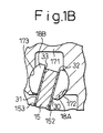
- Fig. 1B an enlarged side sectional view of the essential parts thereof.
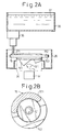
- Fig. 2A is a sectional view of a film forming unit
- Fig. 2B is a plan view showing the manner in which the paint is dripped on an end surface 152 of a swash plate 15.
- Fig. 3A is a sectional view of the paint film remaining on the end surface 152 after the removing operation by centrifugal force
- Fig. 3B is a front view of the paint film remaining on the end surface 152.
- Fig. 4 is a sectional view of a film forming unit according to a second embodiment of the invention.
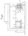
- Fig. 5 is a sectional view showing the manner in which a coating roller 47 is pressed against the swash plate 15.
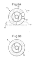
- Fig. 6A is a plan view showing the manner in which the paint is coated on the swash plate 15
- Fig. 6B is a plan view showing a paint film 374 with the surplus portion thereof removed by centrifugal force.
- Fig. 1A shows the internal structure of variable displacement refrigerant compressor.
- a rotary shaft 13 is supported on a front housing 12 and a cylinder block 11 forming a control pressure chamber 121.
- the rotary shaft 13 is driven by an external drive source (such as a vehicle engine).
- a rotary support member 14 is fixedly mounted on the rotary shaft 13, and a swash plate 15 is slidably and inclinably supported along the axis of the rotary shaft 13.
- the swash plate 15 of iron material is formed integrally with a support member 151 on which a guide pin 16 is secured.
- the guide pin 16 is slidably fitted in a guide hole 141 formed in the rotary support member 14.
- the swash plate 15 is rotatable integrally with the rotary shaft 13 and inclinably along the axis of the rotary shaft 13 in collaboration between the guide hole 141 and the guide pin 16.
- the inclination of the swash plate 15 is guided by the slide guide relation between the guide hole 141 and the guide pin 16 on the one hand and the sliding support function of the rotary shaft 13 on the other.
- the inclination angle of the swash plate 15 can be changed by controlling the internal pressure of the control pressure chamber 12. With the increase in the internal pressure of the control pressure chamber 121, the inclination angle of the swash plate 15 decreases, and vice versa.
- the refrigerant in the control pressure chamber 121 flows out to a suction chamber 191 in a rear housing 19 through a discharge passage not shown, and the refrigerant in a discharge chamber 192 in the rear housing 19 is adapted to be supplied to the control pressure chamber 121 through a pressure supply passage not shown.
- a replacement control valve 25 is interposed on the pressure supply passage, so that the flow rate of the refrigerant supplied from the discharge chamber 192 to the control pressure chamber 121 is controlled by a replacement control valve 25.
- the maximum inclination angle of the swash plate 15 is defined by the contact between the swash plate 15 and the rotary support member 14.
- the minimum inclination angle of the swash plate 15, on the other hand, is defined by the contact between the swash plate 15 and a snap ring 24 on the rotary shaft 13.
- a plurality of cylinder bores 111 are arranged around the rotary shaft 13.
- Each cylinder bore 111 contains a piston 17.
- the upper piston 17 is located at the top dead center and the lower piston 17 at the bottom dead center.
- the motion of the swash plate 15 rotated integrally with the rotary shaft 13 is transformed into the longitudinal reciprocal motion of the piston 17 through hemispherical shoes 18A, 18B, so that the piston 17 reciprocates longitudinally in the cylinder bore 111.
- the shoe 18A of iron material is in sliding contact with one sliding contact surface 30 of the swash plate 15 and the shoe 18B of iron material is in sliding contact with the other sliding contact surface 31 of the swash plate 15.
- the refrigerant in the suction chamber 191 flows into the cylinder bore 111 by forcibly pushing off a suction valve 211 on a valve forming plate 21 from a suction port 201 on the valve plate 20.
- the refrigerant that has flowed into the cylinder bore 111 is discharged into a discharge chamber 192 by forcibly pushing off a discharge valve 221 on a valve forming plate 22 from a discharge port 202 on the valve plate 20.
- the opening degree of the discharge valve 221 is controlled by contact with a retainer 231 on a retainer forming plate 23.
- the discharge chamber 192 and the suction chamber 191 are connected to each other through an external refrigerant circuit 26.
- the refrigerant that has flowed out from the discharge chamber 192 to an external refrigerant circuit 26 recirculates into the suction chamber 191 through a condenser 27, an expansion valve 28 and an evaporator 29.
- a holding portion 171 is formed on the piston 17 and has formed thereon a pair of spherical recesses 172, 173.
- the shoe 18A in sliding contact with the sliding contact surface 30 of the swash plate 15 is held unremovably in the recess 172
- the shoe 18B in sliding contact with the other sliding contact surface 31 of the swash plate 15 is held unremovably on the recess 173.
- the end surfaces 152, 153 making up the film forming area are formed with films 32, 33, respectively.
- the surface of the film 32 constitutes the sliding contact surface 30, and the surface of the film 33 makes up the sliding contact surface 31.
- the films 32, 33 are formed by use of a film forming unit shown in Fig. 2A.
- the swash plate 15 is mounted on a rotary holding mechanism 34 rotated in the direction of arrow Q1 by a motor M.
- a receptacle 35 is arranged around the rotary holding mechanism 34.
- a paint container 36 is arranged above the rotary holding mechanism 34.
- a fluid lubrication paint 37 is contained in the paint container 36.
- the lubrication paint 37 includes a thermosetting resin and a solid lubricant such as molybdenum disulfide, tungsten disulfide and graphite.
- a dripping unit 38 is mounted on the bottom wall of the paint container 36. The dripping unit 38 can be switched between the supply mode for allowing the lubrication paint 37 to drip from within the paint container 36 and the stationary mode for not allowing the lubrication paint 37 to drip from within the paint container 36.
- the dripping unit 38 is switched to the supply mode while at the same time rotating the motor M at a speed as low as 10 rpm, for example.
- the lubrication paint 37 in the paint container 36 drips on the end surface 152 of the swash plate 15 rotating at low speed, so that the fluid lubrication paint 37 sequentially attaches along the peripheral direction of the end surface 152 as shown by hatching in Fig. 2B.
- the dripping unit 38 stops while at the same time the motor M is rotated at high speed. A part of the lubrication paint 37 attached on the end surface 152 is removed from the end surface 152 by the centrifugal force due to the high-speed rotation of the swash plate 15. The lubrication paint 37 that has been removed from the end surface 152 by the centrifugal force is pooled in the receptacle 35.
- Figs. 3A, 3B show the coating film 372 of the lubrication paint remaining on the end surface 152.
- the coating film 372 of the lubrication paint remaining on the end surface 152 is dried.
- the swash plate 15 is mounted on the rotary holding mechanism 34 with the end surface 153 directed up.
- the lubrication paint 37 is dripped on the end surface 153, and a part of the lubrication paint 37 attached on the end surface 153 is removed by centrifugal force.
- the coating film 372 on the end surface 152 and the coating film on the end surface 153 become films 32, 33, respectively, through the baking process.
- a first drive unit 42 and a second drive unit 43 are assembled on a base frame 41.
- An intaglio 44 arranged horizontally is driven reciprocally by the first drive unit 42.
- a paint container 45 is arranged just above the intaglio 44.
- the paint container 45 contains the lubrication paint 37.
- the intaglio 44 is reciprocated horizontally at a position of predetermined height in sliding contact with the lower end of the paint container 45. The intaglio 44 thus is reciprocated between the paint supply position shown in Fig. 4 and the paint ready position shown in Fig. 5.
- a band-shaped holding groove 441 is recessed on the upper surface of the intaglio 44.
- the holding groove 441 is located just under the paint container 45.
- the holding groove 441 is located at a paint preparation position S off the position just under the paint container 45. In the case where the intaglio 44 is relocated from the paint ready position to the paint supply position, a part of the paint in the paint container 45 is filled in the holding groove 441.
- a support base plate 40 is fixedly secured at the lower end of a support shaft 39 movable both vertically and horizontally by the second drive unit 43.
- a motor 46 is mounted on the lower surface of the support base plate 40.
- a coating roller 47 of rubber is securely fixed on the output shaft 461 of the motor 46.
- a motor M and a rotary holding mechanism 34 are arranged on the extension of the intaglio 44.
- the swash plate 15 is mounted on the rotary holding mechanism 34.
- the width of the coating roller 47 is approximately equal to the width of the end surface 152 of the swash plate 15.
- the coating roller 47 is moved along the arrows r1, r2, r3 in that order by the operation of the second drive unit 43.
- the coating roller 47 rotates in the direction along arrow Q2 at the same peripheral speed as the travel speed of the coating roller 47, so that the lubrication paint 373 prepared in the holding groove 441 is transferred to the peripheral surface of the coating roller 47.
- the coating roller 47 is rotated in sliding contact with the intaglio 44 in such a manner that the side (lower side in the drawing) of the coating roller 47 pressed against the intaglio 44 is moved in advance in the same direction as the travel direction of the coating roller 47.
- the coating roller 47 with the coating film 374 attached thereon is moved along arrows r4, r5, r6, r7 in that order by the operation of the second drive unit 43.
- the coating roller 47 rotates in the direction indicated by arrow Q3, so that the coating film 374 attached on the peripheral surface of the coating roller 47 is transferred to the end surface 152 of the swash plate 15.
- the rotational speed at the transverse center of the end surface 152 is equal to the peripheral speed of the coating roller 47.
- the coating roller 47 comes into sliding contact with the swash plate 15 by rotating in such a manner that the side (the lower side in Fig. 5) of the coating roller 47 pressed against the swash plate 15 moves in advance in the same direction as that of the relative motion of the coating roller 47.
- the coating film 374 on the coating roller 47 is transferred to the end surface 152 as the coating roller 47 comes into sliding contact with the swash plate 15.
- Fig. 6B shows the coating film 374 after removal of the surplus portion thereof by the centrifugal force.
- a similar coating film is formed also on the end surface 153. Once the coating film is dried and baked, the films 32, 33 are obtained.
- the second embodiment has the following advantages.
- the present invention may be additionally embodied in the following ways.
- a fluid paint is attached to a film forming area of a part to be formed with a film, and the surplus portion of the fluid paint attached to the film forming area is removed by centrifugal force thereby to form a film. Therefore, the invention has a great advantage that a film of high quality can be formed on a part of the compressor to be formed with a film.
Landscapes
- Engineering & Computer Science (AREA)
- Mechanical Engineering (AREA)
- General Engineering & Computer Science (AREA)
- Compressors, Vaccum Pumps And Other Relevant Systems (AREA)
- Compressor (AREA)
Applications Claiming Priority (2)
| Application Number | Priority Date | Filing Date | Title |
|---|---|---|---|
| JP2000044714A JP2001234860A (ja) | 2000-02-22 | 2000-02-22 | 圧縮機の皮膜形成対象部品及び皮膜形成対象部品における皮膜形成方法 |
| JP2000044714 | 2000-02-22 |
Publications (1)
| Publication Number | Publication Date |
|---|---|
| EP1128066A2 true EP1128066A2 (de) | 2001-08-29 |
Family
ID=18567432
Family Applications (1)
| Application Number | Title | Priority Date | Filing Date |
|---|---|---|---|
| EP01103560A Pending EP1128066A2 (de) | 2000-02-22 | 2001-02-19 | Taumelscheibe mit Beschichtung |
Country Status (3)
| Country | Link |
|---|---|
| US (1) | US20010015130A1 (de) |
| EP (1) | EP1128066A2 (de) |
| JP (1) | JP2001234860A (de) |
Families Citing this family (3)
| Publication number | Priority date | Publication date | Assignee | Title |
|---|---|---|---|---|
| JP2003278742A (ja) * | 2002-03-26 | 2003-10-02 | Daido Metal Co Ltd | 両面摺動スラスト軸受 |
| EP1970566A2 (de) * | 2007-03-12 | 2008-09-17 | Kabushiki Kaisha Toyota Jidoshokki | Verdichter mit variabler Verdrängung |
| JPWO2014057568A1 (ja) * | 2012-10-11 | 2016-08-25 | サンデンホールディングス株式会社 | ディスク状基材への摺動用塗料の塗布方法 |
Citations (3)
| Publication number | Priority date | Publication date | Assignee | Title |
|---|---|---|---|---|
| JPH1026081A (ja) | 1996-07-08 | 1998-01-27 | Toyota Autom Loom Works Ltd | 圧縮機のピストン及び同ピストンへのコーティング方法 |
| JPH11173263A (ja) | 1997-10-09 | 1999-06-29 | Toyota Autom Loom Works Ltd | 斜板式圧縮機 |
| JPH11193780A (ja) | 1997-12-26 | 1999-07-21 | Toyota Autom Loom Works Ltd | 片頭ピストン型斜板式圧縮機および斜板の製造方法 |
-
2000
- 2000-02-22 JP JP2000044714A patent/JP2001234860A/ja active Pending
-
2001
- 2001-02-19 US US09/788,217 patent/US20010015130A1/en not_active Abandoned
- 2001-02-19 EP EP01103560A patent/EP1128066A2/de active Pending
Patent Citations (3)
| Publication number | Priority date | Publication date | Assignee | Title |
|---|---|---|---|---|
| JPH1026081A (ja) | 1996-07-08 | 1998-01-27 | Toyota Autom Loom Works Ltd | 圧縮機のピストン及び同ピストンへのコーティング方法 |
| JPH11173263A (ja) | 1997-10-09 | 1999-06-29 | Toyota Autom Loom Works Ltd | 斜板式圧縮機 |
| JPH11193780A (ja) | 1997-12-26 | 1999-07-21 | Toyota Autom Loom Works Ltd | 片頭ピストン型斜板式圧縮機および斜板の製造方法 |
Also Published As
| Publication number | Publication date |
|---|---|
| JP2001234860A (ja) | 2001-08-31 |
| US20010015130A1 (en) | 2001-08-23 |
Similar Documents
| Publication | Publication Date | Title |
|---|---|---|
| EP0818625B1 (de) | Vorrichtung zur Beschichtung von Kompressorkolben | |
| AU688070B2 (en) | Variable displacement piston type compressor | |
| KR100327083B1 (ko) | 사판식 압축기 | |
| EP1128066A2 (de) | Taumelscheibe mit Beschichtung | |
| JP3259215B2 (ja) | 圧縮機のピストン及び同ピストンへのコーティング方法 | |
| EP1008752A2 (de) | Kompressorkolben, und Verfahren zu ihrer Beschichtung | |
| KR100327084B1 (ko) | 사판식 압축기 | |
| US6694864B2 (en) | Swash plate type compressor | |
| EP0995905A2 (de) | Kompressorkolben | |
| KR100337857B1 (ko) | 압축기용 피스톤의 코팅막 형성 방법 및 그 장치 | |
| JPH10299654A (ja) | ピストン式圧縮機 | |
| EP1091121A2 (de) | Filmbeschichteter Kolben | |
| JPH11201037A (ja) | 圧縮機のピストン及びピストンの製造方法 | |
| US20030000376A1 (en) | Swash plate of swash plate type compressor | |
| JP2001234861A (ja) | 圧縮機の皮膜形成対象部品及び皮膜形成対象部品における皮膜形成方法 | |
| KR100388827B1 (ko) | 압축기용 피스톤의 코팅막 형성 방법 및 그 장치 | |
| EP1136699A2 (de) | Verfahren zum Aufbringen eines Films auf die Taumelscheibe eines Kompressors | |
| KR100497976B1 (ko) | 가변용량형 사판식 압축기용 피스톤 코팅장치 및 방법 | |
| JP2001234853A (ja) | 斜板式圧縮機における斜板 | |
| EP0961030A2 (de) | Schmierung von Kolben im Kurbelgehäuse eines Taumelscheibenkompressors | |
| JPH11201038A (ja) | 圧縮機のピストン | |
| JPH10196527A (ja) | 斜板式圧縮機 | |
| JP2000291539A (ja) | 容量可変型斜板式圧縮機 | |
| JPH03189379A (ja) | 可変容量往復動コンプレツサ |
Legal Events
| Date | Code | Title | Description |
|---|---|---|---|
| PUAI | Public reference made under article 153(3) epc to a published international application that has entered the european phase |
Free format text: ORIGINAL CODE: 0009012 |
|
| 17P | Request for examination filed |
Effective date: 20010219 |
|
| AK | Designated contracting states |
Kind code of ref document: A2 Designated state(s): AT BE CH CY DE DK ES FI FR GB GR IE IT LI LU MC NL PT SE TR |
|
| AX | Request for extension of the european patent |
Free format text: AL;LT;LV;MK;RO;SI |
|
| RAP1 | Party data changed (applicant data changed or rights of an application transferred) |
Owner name: KABUSHIKI KAISHA TOYOTA JIDOSHOKKI |
|
| 18W | Application withdrawn |
Withdrawal date: 20021108 |
|
| STAA | Information on the status of an ep patent application or granted ep patent |
Free format text: STATUS: THE APPLICATION HAS BEEN WITHDRAWN |
|
| D18W | Application withdrawn (deleted) | ||
| R18W | Application withdrawn (corrected) |
Effective date: 20021108 |