EP1128087A2 - Die Einrichtung einer Brennkraftmaschine zur Montage einer Ausgleichsvorrichtung - Google Patents
Die Einrichtung einer Brennkraftmaschine zur Montage einer Ausgleichsvorrichtung Download PDFInfo
- Publication number
- EP1128087A2 EP1128087A2 EP01102599A EP01102599A EP1128087A2 EP 1128087 A2 EP1128087 A2 EP 1128087A2 EP 01102599 A EP01102599 A EP 01102599A EP 01102599 A EP01102599 A EP 01102599A EP 1128087 A2 EP1128087 A2 EP 1128087A2
- Authority
- EP
- European Patent Office
- Prior art keywords
- balancer
- crankshaft
- combustion engine
- internal combustion
- crankcase
- Prior art date
- Legal status (The legal status is an assumption and is not a legal conclusion. Google has not performed a legal analysis and makes no representation as to the accuracy of the status listed.)
- Granted
Links
- 238000002485 combustion reaction Methods 0.000 title claims abstract description 61
- 239000007858 starting material Substances 0.000 claims abstract description 18
- 230000005540 biological transmission Effects 0.000 description 14
- XLYOFNOQVPJJNP-UHFFFAOYSA-N water Substances O XLYOFNOQVPJJNP-UHFFFAOYSA-N 0.000 description 4
- 238000010276 construction Methods 0.000 description 3
- 230000001154 acute effect Effects 0.000 description 1
- 239000000498 cooling water Substances 0.000 description 1
- 239000002828 fuel tank Substances 0.000 description 1
- 230000010363 phase shift Effects 0.000 description 1
- 230000003014 reinforcing effect Effects 0.000 description 1
Images


Classifications
-
- F—MECHANICAL ENGINEERING; LIGHTING; HEATING; WEAPONS; BLASTING
- F02—COMBUSTION ENGINES; HOT-GAS OR COMBUSTION-PRODUCT ENGINE PLANTS
- F02B—INTERNAL-COMBUSTION PISTON ENGINES; COMBUSTION ENGINES IN GENERAL
- F02B61/00—Adaptations of engines for driving vehicles or for driving propellers; Combinations of engines with gearing
- F02B61/02—Adaptations of engines for driving vehicles or for driving propellers; Combinations of engines with gearing for driving cycles
-
- F—MECHANICAL ENGINEERING; LIGHTING; HEATING; WEAPONS; BLASTING
- F16—ENGINEERING ELEMENTS AND UNITS; GENERAL MEASURES FOR PRODUCING AND MAINTAINING EFFECTIVE FUNCTIONING OF MACHINES OR INSTALLATIONS; THERMAL INSULATION IN GENERAL
- F16F—SPRINGS; SHOCK-ABSORBERS; MEANS FOR DAMPING VIBRATION
- F16F15/00—Suppression of vibrations in systems; Means or arrangements for avoiding or reducing out-of-balance forces, e.g. due to motion
- F16F15/22—Compensation of inertia forces
- F16F15/26—Compensation of inertia forces of crankshaft systems using solid masses, other than the ordinary pistons, moving with the system, i.e. masses connected through a kinematic mechanism or gear system
- F16F15/264—Rotating balancer shafts
- F16F15/265—Arrangement of two or more balancer shafts
-
- F—MECHANICAL ENGINEERING; LIGHTING; HEATING; WEAPONS; BLASTING
- F02—COMBUSTION ENGINES; HOT-GAS OR COMBUSTION-PRODUCT ENGINE PLANTS
- F02B—INTERNAL-COMBUSTION PISTON ENGINES; COMBUSTION ENGINES IN GENERAL
- F02B2275/00—Other engines, components or details, not provided for in other groups of this subclass
- F02B2275/18—DOHC [Double overhead camshaft]
Definitions
- the present invention relates to a balancer-fitting configuration of an internal combustion engine.
- the internal combustion engine 01 disclosed in the above patent publication has a cylinder 02 which is inclined a little forward and balancers 04 and 05 which are disposed generally above and below a crankshaft 03, within the maximum width of the locus of the crank weight of the crankshaft 03, the width taken in the longitudinal direction of the vehicle which is fitted with the internal combustion engine.
- the length of the internal combustion engine in the longitudinal direction of the vehicle is made small.
- the idler gear 06 is disposed between the crankshaft 03 and the upper balancer 04 and protruding backward relatively to them, the part of the crankcase behind the crankshaft 03 is bulky. Accordingly, the rear wheel has to be disposed more backward to avoid the interference between the crankcase and the rear wheel, making the frame large.
- the present invention was made in view of the above problem. Its object is to provide a balancer-fitting configuration of an internal combustion engine. With the balancer-fitting configuration, (i) the vibration control of an internal combustion engine with forward-inclined cylinders is achieved effectively by using paired balancers separated and disposed opposite to each other, (ii) the part of the crankcase behind the crankshaft is made small in the longitudinal direction of the frame, and (iii), thereby, a space wherein the real wheel swings is secured without enlarging the frame.
- a balancer-fitting configuration of an internal combustion engine with a crankcase, a crankshaft, and a crank weight for a vehicle with a rear wheel disposed close to the rear of the crankcase wherein (i) the cylinder axial line of the internal combustion engine is inclined generally horizontally, and paired balancers, one above and the other below the crankshaft, are disposed generally within the maximum width of the locus of the crank weight, the width being taken in the longitudinal direction of the vehicle, and (ii) a starter is disposed in the vicinity of the upper balancer, and accessories such as an oil pump are disposed in the vicinity of the lower balancer.
- the balancers can be positioned symmetrically in relation to the cylinder axial line, the crankshaft being the center between the balancers.
- the rotation of the upper and lower balancers does not cause moment to the crankshaft, and the vibration can effectively be controlled with the paired balancers separated from each other without concern about a new factor of vibration.
- the paired balancers are within the maximum width of the locus of the crank weight, the width taken in the longitudinal direction of the vehicle, the part of the crankcase behind the crankshaft can be made small in the same direction.
- the starter and the oil pump are disposed in the vicinities of the balancers.
- the length of the internal combustion engine including the starter and the oil pump is made small, and a space wherein the rear wheel behind the crankcase swings can be secured without enlarging the frame.
- the starter is disposed before the upper balancer shaft which is disposed behind the crankshaft, the starter does not largely protrude upward.
- the starter is positioned within the maximum width of the locus of the crank weight, the width taken in the longitudinal direction of the vehicle, the starter does not protrude forward.
- the internal combustion engine can be made compact.
- the accessories are disposed before the lower balancer shaft, the accessories do not affect the ground clearance of the frame.
- An internal combustion engine with cylinders inclined generally horizontally tends to be long.
- the distance from the internal combustion engine to the rear wheel can be shortened by configuring the crankshaft and the arm supporting the rear wheel at its rear end so that the arm can swing about a shaft in axial alignment with the crankshaft.
- the frame can be made small in length.
- a balancer-fitting configuration of an internal combustion engine comprising a crankcase, a crankshaft, and a balancer which has a shaft parallel to the crankshaft, wherein (i) a driving gear fitted on the crankshaft and a balancer driven gear fitted on the balancer shaft engage with each other to transmit motive power, (ii) the balancer driven gear is a scissors gear comprising two spur gears which are put together side by side and urged to slip out of the exactly overlapping state of the tooth profiles of one spur gear and those of the other, and (iii) a positioning pin fixes the two spur gears of the balancer driven gear in the exactly overlapping state of the tooth profiles of one spur gear and those of the other and positions the balancer driven gear with respect to the crankcase.
- the balancer driven gear is a scissors gear, the rotation is transmitted smoothly.
- the positioning pin fixes the two spur gears in the exactly overlapping state of the tooth profiles of one spur gear and those of the other and positions the balancer driven gear with respect to the crankcase, the phase matching of the balancer can easily be made when it is built in the internal combustion engine. Thus, the assembling efficiency is raised significantly.
- the positioning pin can be removed through the through hole of the crankcase after the balancer is built in the internal combustion engine, the assembling efficiency is high.
- Fig. 1 is a whole side view of a scooter-type motorcycle to which an internal combustion engine of an embodiment of the present invention is applied.
- Fig. 2 is a side view of an internal combustion engine and a belt-type automatic transmission partially sectioned and partially omitted.
- Fig. 3 is a cross-sectional view of the device in Fig. 1 sectioned along the line III-III.
- Fig. 4 is a right side view of an internal combustion engine whose case cover is removed.
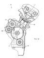
- Fig. 5 is a right side view of an internal combustion engine whose right crankcase half is removed.
- Fig. 6 is a cross-sectional view of the device in Fig. 4 sectioned along the line VI-VI.
- Fig. 7 is a cross-sectional view of the device in Fig. 4 sectioned along the line VII-VII.
- Fig. 8 is a right side view of a balancer shaft and a balancer driven gear.
- Fig. 9 is a cross-sectional view of the device in Fig. 8 sectioned along the line IX-IX.
- Fig. 10 is a cross-sectional view of a principal part of a conventional internal combustion engine.
- An internal combustion engine in accordance with the embodiment is applied to a scooter-type motorcycle 1, of which the whole side view is shown in Fig. 1.
- a pair of main pipes 3 and 3 extends backward, downward straight from the upper part of a head pipe 2 as seen from the left side.
- a pair of right and left support pipes 4 and 4 extends generally horizontally, backward from the lower part of the head pipe 2 to connect with the main pipes 3 and 3 and support their front parts.
- paired right and left down pipes 5 and 5 extend downward at an acute angle, the space between them expanding, to form front vertical sections 5a and 5a.
- the down pipes 5 and 5 bend backward to form middle horizontal sections 5b and 5b.
- the down pipes 5 and 5 bend upward to form rear slant sections 5c and 5c.
- the rear ends of the main pipes 3 and 3 are connected with the lower parts of the rear slant sections 5c and 5c, the main pipe 3 and the down pipe 5 taking a triangular shape as seen from each side of the frame.
- a reinforcing pipe 6 is connected between the main pipe 3 and the down pipe 5 on each side.
- the upper end of the rear slant section 5c of the down pipe 5 is connected with the middle part of the seat rail 7 to support it.
- a steering shaft 11 is journaled in the head pipe 2.
- handlebars 12 and 12 extending right and left, respectively.
- Extending below the head pipe 2 is a front fork 13.
- a font wheel 14 is journaled on a shaft at the bottom of the front fork 13.
- the internal combustion engine 20 is of the four-stroke cycle and has two cylinders. Its crankcase 21 is disposed behind the rear slant sections 5c of the down pipes 5. A cylinder block 22, a cylinder head 23, and a cylinder head cover 24 are placed, one on top of another in the order of their description, on the crankcase 21 and joined together, the assembly of the cylinder block 22, the cylinder head 23, and the cylinder head cover 24 taking a largely forward-inclined posture and protruding beyond the rear slant sections 5c of the down pipes 5.
- the cylinder block 22, the cylinder head 23, and the cylinder head cover 24 are disposed between the right and left triangles formed by the rear slant sections 5c of the down pipes 5, the rear parts of the main pipes 3, and the front parts of the seat rails 7 on the right and left sides of the frame.
- a mounting bracket 21a protruding from the top of the crankcase 21 and another mounting bracket 21b protruding from the front of the crankcase 21 are supported by the supporting brackets 5d and 5e, respectively, through the media of supporting shafts 8 and 9, respectively.
- the internal combustion engine 20 is suspended from the frame.
- a belt-type automatic transmission 50 is pivoted at its front to the crankcase 21 of the internal combustion engine 20 and extends backward.
- a rear wheel 15 is journaled at the rear of the belt-type automatic transmission 50.
- Intake pipes 31 and 31 extend upward from the cylinders of the forward-inclined cylinder head 23 of the internal combustion engine 20 and bend backward to connect with carburetors 32 and 32 disposed laterally side by side, above the crankcase 21.
- the carburetors 32 and 32 connect with an air cleaner 33 disposed behind them.
- the air cleaner 33 is disposed between the right and left seat rails 7 and 7. Above the air cleaner 33, a helmet-containing box 34 is supported by the seat rails 7 and 7.
- a rider's seat 35 is disposed freely openably and closably over the internal combustion engine 20 and the carburetors 32, and a pillion 36 is disposed freely openably and closably over the helmet-containing box 34 and the part behind it.
- Exhaust pipes 37 and 37 extend from the cylinder head 23 downward, go to the right in front of the crankcase 21, further extend backward along the right side of the crankcase 21, and join into a single pipe, which goes upward, backward along the right side of the frame and connects with a muffler 38 supported on the right side of the rear wheel 15.
- a fuel tank 39 is enclosed and supported by the four pipes; i.e., the upper right and left main pipes 3 and 3 and the front and lower, right and left down pipes 5 and 5.
- belt-type automatic transmission 50 which is pivoted at its front to the crankcase 21 of the internal combustion engine 20, will be described below.
- the crankcase 21 is split into right and left halves 21R and 21L. As shown in Fig. 3, a crankshaft 25 is disposed horizontally, laterally relatively to the frame, in the crankcase 21.
- the outer rotor 29a of an AC generator 29 is fitted on the right end of the crankshaft 25.
- a case cover 28 is fitted to the right crankcase half 21R to cover the side of the outer rotor 29a.
- the inner stator 29b of the AC generator 29 is supported on the case cover 28.
- Pistons 26 and 26 which reciprocate slidingly in two cylinder sleeves 30 in the cylinder block 22, are connected to crank pins of the crankshaft 25 through connecting rods 27 and 27.
- crank pins have a phase shift of 360 degrees.
- the cylinder head 23 is provided with a valve system 40.
- Camshafts 41 and 41 are disposed horizontally, laterally relatively to the frame, one up and one down.
- Cam-chain sprocket wheels 42 and 42 are fitted on the right ends of the camshafts 41 and 41.
- a drive-chain sprocket wheel 43 is fitted on such a part of the crankshaft 25 protruding through the right crankcase half 21R as is immediately outside of the right crankcase half 21R.
- a timing chain 44 is laid around the drive-chain sprocket wheel 43 and the cam-chain sprocket wheels 42 and 42 to transmit the motive power from the former to the latter.
- the timing chain 44 is laid through cam-chain chambers 22a and 23a formed on the right side of the cylinder block 22 and the cylinder head 23.
- the camshafts 41 and 41 drive inlet valves 45 and the exhaust valves 46 in accordance with prescribed timing.
- the belt-type automatic transmission 50 is pivoted to the crankcase 21 of the internal combustion engine 20.
- the case cover 28, which closes the right opening of the right crankcase half 21R and covers the AC generator 29, has an opening coaxial with the crankshaft 25.
- a rotation shaft 55 is supported in the opening through the medium of a bearing 54 so as to protrude to the right of the case cover 28.
- a base end part 51a of a right transmission-case section 51 of the belt-type automatic transmission 50 is fitted on the protruding part of the rotation shaft 55.
- the right transmission-case section 51 includes a connecting part 51b which extends from the base end part 51a, bends inwardly, and further extends along the back of the right crankcase half 21R.
- bosses 51c Formed at two spots on the back of the connecting part 51b are bosses 51c which protrude backward.
- Two left-facing joints, or joining faces, on the front end of a right fork member 53 are brought and fitted to two right-facing joints, or joining faces, on the bosses 51c and they are secured to each other by bolts 56.
- the right fork member 53 is joined to the right transmission-case section 51 and extends backward.
- crankshaft 25 protrudes through a left crankcase half 21L.
- a drive pulley 60 with a centrifugal speed-changing mechanism is fitted on the protruding part of the crankshaft 25.
- An annular supporting member 57 is fixed on the outer surface of the left crankcase half 21L, around the crankshaft 25 protruding through the left crankcase half 21L.
- a left transmission-case section 52 is pivoted at its base end part 52a about the annular supporting members 57 through the medium of a bearing 58 so as to be freely swingable.
- the left transmission-case section 52 includes a connecting part 52b which extends from a base end part 52a, bends inwardly, and further extends along the back of the left crankcase half 21L.
- the left transmission-case section 52 includes also a left fork part 52c which extends backward.
- a joint, or joining face, of the connecting part 51b of the right transmission-case section 51 which bends inwardly from the right side of the crankcase 21 and extends along the back of the crankcase 21 and a joint, or joining face of the connecting part 52b of the left transmission-case section 52 which bends inwardly from the left side of the crankcase 21 and extends along the back of the crankcase 21 are brought and fitted to each other and secured to each other by four bolts 59.
- the right and left transmission-case sections 51 and 52 are joined together, and thereby the left fork part 52c and the right fork member 53 are connected together as a unit, each taking its position opposite to that of the other.
- the left transmission-case section 51 is pivoted so as to swing freely about the crankshaft 25 through the medium of the bearing 54 and the left transmission-case section 52 is pivoted so as to swing freely about the crankshaft 25 through the medium of the bearing 58, the left fork part 52c and the right fork member 53 are supported so as to swing, as a unit, up and down freely about the crankshaft 25.
- the rear portion of the left fork part 52c of the left transmission-case section 52 constitutes a transmission chamber.
- a driven shaft 64 is journaled in the transmission chamber.
- a driven pulley 62 is journaled about the driven shaft 64 through a centrifugal clutch 63.
- a V-belt 61 is laid around the driven pulley 62 and the drive pulley 60 described earlier to constitute a belt-type speed-changing mechanism.
- a speed-reducing mechanism of a transmission gear group 65a wherein driving force is transmitted from the driven shaft 64 through a countershaft 65 to an axle 66.
- the axle 66 is provided between the left fork part 52c and the right fork member 53 so as to be freely rotatable, and the rear wheel 15 is supported by the axle 66 between the left fork part 52c and the right fork member 53.
- the right and left transmission-case sections 51 and 52 wherein the belt-type automatic transmission 50 is supported, are pivoted so that the left fork part 52c, the right fork member 53, and the rear wheel 15 can swing freely about the crankshaft 25.
- the frame can be made small in length.
- a rear cushion 67 is fitted between the rear end of the left transmission-case section 52 and the rear end of the seat rail 7.
- a belt cover 68 closes the left opening of the left transmission-case section 52 containing the belt-type automatic transmission 50 and covers the belt-type automatic transmission 50 from its left side.
- the internal combustion engine 20 has paired balancer shafts 71 and 72, one above and the other below the crankshaft 25.
- the upper and lower balancer shafts 71 and 72 are disposed generally symmetrically in relation to the cylinder axial line C-C'.
- both balancers 71a and 72a are within the maximum width "R" of the rotational locus of a crank weight 25a of the crankshaft 25, the width "R” taken in the longitudinal direction of the frame.
- a driving gear 73 is fitted on the crankshaft 25, by the inner surface of the right crankcase half 21R.
- Balancer driven gears 74 and 75 which are fitted on the balancer shafts 71 and 72, respectively, engage simultaneously with the driving gear 73. Accordingly, while the crankshaft 25 is rotating, both the balancer shafts 71 and 72 rotate in the same direction.
- the vibration can effectively be controlled with the separated-two-shaft balancer mechanism without concern about a new factor of vibration.
- the paired balancers 71a and 72a are disposed above and below the crankshaft 25, respectively, and generally within the maximum width "R" of the rotational locus of the crank weight 25a, the width taken in the longitudinal direction of the frame, the distance "W” from the crankshaft 25 to the rear wall of the crankcase 21 can be made small.
- crankshaft 25 and the rear wheel 15 are configured so that the latter swings about the former as described earlier, the distance from the internal combustion engine 20 to the rear wheel 15 and, hence, the overall length of the frame can be reduced further by bringing the rear wheel 15 close to the crankcase 21 wherein the distance "W" from the crankshaft 25 to the rear wall of the crankcase 21 is reduced.
- the frame can be made compact, and a space wherein the rear wheel 15 swings can be secured behind the crankcase 21.
- the mounting bracket 21a which protrudes from the crankcase 21.
- a starter motor 100 is disposed before the mounting bracket 21a. Because the heavy components of the starter motor 100 and the upper balancer 71a are disposed near the mounting bracket 21a (refer to Figs. 4 and 5), the moment of inertia around the engine support is small, which is advantageous against the vibration of the frame.
- the driving gear 100a of the driving shaft of the starter motor 100 engages with the large gear 101a of the first counter shaft 101.
- a small gear 101b provided as a unit with the large gear 101a engages with a gear 102a of the second countershaft 102.
- the gear 102a engages with a driven gear 103 fitted on the crankshaft 25, the driven gear 103 taking a position by the outer rotor 29a of the AC generator 29.
- the rotation of the driving shaft of the starter motor 100 is transmitted to the crankshaft 25 for the startup.
- the starter motor 100 is disposed before the mounting bracket 21a at the same height, and it does not protrude upward largely.
- the mounting bracket 21a and the starter motor 100 are disposed within the maximum width "R" of the rotational locus of the crank weight 25a, the width taken in the longitudinal direction of the frame. Thus, they do not affect the length of the internal combustion engine 20 and contribute to the reduction of the frame size.
- a pump-driving shaft 80 is disposed in parallel with and below the lower balancer shaft 72 off to the front.
- a chain 82 is laid around a driving sprocket wheel 93 fitted on the right end of the lower balancer shaft 72 protruding through the right crankcase half 21R and a driven sprocket wheel 81 fitted on the right end of the pump-driving shaft 80 (see Figs. 4 and 7).
- crankshaft 25 rotates the pump-driving shaft 80 through the lower balancer shaft 72.
- An oil pump 85 is disposed between the right crankcase half 21R and the driven sprocket wheel 81 on the right end of the pump-driving shaft 80.
- a water pump 86 is fitted on the part of the pump-driving shaft 80 protruding through the left crankcase half 21L (see Fig. 7).
- a suction-connecting pipe 87 protrudes forward from the space to the left of the center of the impeller 86a of the water pump 86.
- a discharge-connecting pipe 88 protrudes upward from one side of the impeller 86a.
- a hose 89 connects the discharge-connecting pipe 88 and a connecting pipe 91 protruding from a cooling-water inlet provided on the left side of the cylinder block 22 (see Fig. 2).
- An oil filter 92 protrudes forward from the lower part of the front wall of the left crankcase half 21L.
- the oil pump 85 and the water pump 86 are provided at the ends of the pump-driving shaft 80 which is disposed close to and below the lower balancer shaft 72 off to the front. Because both the oil pump 85 and the water pump 86 are disposed before and close to the lower balancer shaft 72, they hardly affect the ground clearance of the frame and, hence, do not impede making the internal combustion engine 20 small.
- the balancer driven gears 74 and 75 which are fitted on the balancer shafts 71 and 72 and engage with the driving gear 73 fitted to the crankshaft 25 to transmit the rotation of the crankshaft 25 to the upper and lower balancer shafts 71 and 72, are scissors gears for smooth rotational transmission, each consisting of two spur gears which are put together side by side and urged to slip out of the exactly overlapping state of the tooth profiles of one gear and those of the other.
- the balancer driven gear 75 comprises a main gear 75a, which is a spur gear, and a sub-gear 75b, which is a thin spur gear.
- the main gear 75a and the sub-gear 75b are put together side by side and journaled so as to be freely rotatable relatively to each other.
- the sub-gear 75b is journaled on the axle portion of the main gear 75a and prevented from coming off the axle portion by a circlip, or a snap ring, 77 so as to be freely rotatable relatively to the main gear 75a.
- Three springs 76 are fitted between the main gear 75a and the sub-gear 75b to urge them to slip out of the exactly overlapping state of the tooth profiles of the main gear 75a and those of the sub-gear 75b.
- a threaded hole 75ah is made at a prescribed point on the main gear 75a, and an oval hole 75bh is made at a prescribed point on a concentric circle on the sub-gear 75b.
- a positioning pin 79 that is, a bolt having a hexagon socket head cap screw is screwed into the threaded hole 75ah through the oval hole 75bh so that the head of the positioning pin or the bolt 79 can check the turn of the sub-gear 75b relative to the main gear 75a and, thereby, fix the overlap of the tooth profiles of the main gear 75a and those of the sub-gear 75b in a certain state (see Fig. 6).
- the balancer driven gear 75 can easily be brought into engagement with the driving gear 73 of the crankshaft 25.
- the assembling efficiency can be raised.
- the balancer driven gear 74 fitted on the upper balancer shaft 71 is a scissors gear with the same construction.
- the main gear 74a and the sub-gear 74b can be fixed by a bolt 78 in the exactly overlapping state of the tooth profiles of the main gear 74a and those of the sub-gear 74b.
- the bolts 78 and 79 of the balancer driven gears 74 and 75 are also used for the phase matching of the upper and lower balancers 71a and 72a when they are built in.
- the phase matching of the balancers 71a and 72a is made so that bolts 78 and 79 are located at a given angled position by engaging the balancer driven gears 74 and 75 with the driving gear 73 of the crankshaft 25 in the state of the angle of the crankshaft 25 with the pistons 26 and 26 at the top dead center.
- the bolts 78 and 79 can be removed by making use of the position-matching holes 21Ra and 21Rb of the right crankcase half 21R.
- the springs 76 urge the main gears 74a and 75a as well as the sub-gears 74b and 75b of the balancer driven gears 74 and 75 to slip out of the exactly overlapping state of the tooth profiles of one gear and those of the other. Since teeth of the driving gear 73 of the crankshaft 25 are expanded by the action of the spring 76 and engage with each other, the rotation is transmitted smoothly.
- the invention provides a balancer-fitting configuration of an internal combustion engine.
- the vibration control of an internal combustion engine with forward-inclined cylinders is achieved effectively by using paired balancers separated and disposed opposite to each other, the part of the crankcase behind the crankshaft is made small in the longitudinal direction of the frame, and thereby, a space wherein the real wheel swings is secured without enlarging the frame.
Landscapes
- Engineering & Computer Science (AREA)
- General Engineering & Computer Science (AREA)
- Mechanical Engineering (AREA)
- Acoustics & Sound (AREA)
- Combustion & Propulsion (AREA)
- Physics & Mathematics (AREA)
- Chemical & Material Sciences (AREA)
- Aviation & Aerospace Engineering (AREA)
- Cylinder Crankcases Of Internal Combustion Engines (AREA)
- Arrangement Or Mounting Of Propulsion Units For Vehicles (AREA)
- Axle Suspensions And Sidecars For Cycles (AREA)
- Automatic Cycles, And Cycles In General (AREA)
- Lubrication Of Internal Combustion Engines (AREA)
Applications Claiming Priority (2)
| Application Number | Priority Date | Filing Date | Title |
|---|---|---|---|
| JP2000045214A JP3960450B2 (ja) | 2000-02-22 | 2000-02-22 | 内燃機関のバランサ組付構造 |
| JP2000045214 | 2000-02-22 |
Publications (3)
| Publication Number | Publication Date |
|---|---|
| EP1128087A2 true EP1128087A2 (de) | 2001-08-29 |
| EP1128087A3 EP1128087A3 (de) | 2004-03-10 |
| EP1128087B1 EP1128087B1 (de) | 2007-11-28 |
Family
ID=18567835
Family Applications (1)
| Application Number | Title | Priority Date | Filing Date |
|---|---|---|---|
| EP01102599A Expired - Lifetime EP1128087B1 (de) | 2000-02-22 | 2001-02-06 | Kraftfahrzeug mit einer Brennkraftmaschine ausgelegt zur Montage einer Ausgleichsvorrichtung |
Country Status (7)
| Country | Link |
|---|---|
| US (1) | US6397810B2 (de) |
| EP (1) | EP1128087B1 (de) |
| JP (1) | JP3960450B2 (de) |
| CN (1) | CN1144722C (de) |
| DE (1) | DE60131584T2 (de) |
| ES (1) | ES2296677T3 (de) |
| TW (1) | TW489966U (de) |
Cited By (6)
| Publication number | Priority date | Publication date | Assignee | Title |
|---|---|---|---|---|
| FR2830591A1 (fr) * | 2001-10-04 | 2003-04-11 | Renault | Groupe d'arbres d'equilibrage pour moteur a combustion interne |
| EP1389554A1 (de) * | 2002-08-13 | 2004-02-18 | Bombardier-Rotax GmbH & Co. KG | Viertakt-Brennkraftmaschinenanordnung |
| US6929081B2 (en) | 2002-08-13 | 2005-08-16 | Brp-Rotax Gmbh & Co. Kg | Engine arrangement for a four cycle engine |
| EP1529983A3 (de) * | 2003-10-04 | 2005-10-12 | DaimlerChrysler AG | Brennkraftmaschine mit mehreren Zylindern und einer Vorrichtung zum Massenausgleich |
| WO2007022745A1 (de) * | 2005-08-25 | 2007-03-01 | Luk Lamellen Und Kupplungsbau Beteiligungs Kg | Verbesserte keilnutverbindung |
| EP3321161A1 (de) * | 2016-11-09 | 2018-05-16 | Yamaha Hatsudoki Kabushiki Kaisha | Grätschsitzfahrzeug |
Families Citing this family (24)
| Publication number | Priority date | Publication date | Assignee | Title |
|---|---|---|---|---|
| JP3891756B2 (ja) * | 2000-03-31 | 2007-03-14 | 本田技研工業株式会社 | 内燃機関の潤滑構造 |
| JP3867486B2 (ja) * | 2000-09-06 | 2007-01-10 | スズキ株式会社 | 自動二輪車 |
| US6655340B2 (en) * | 2001-10-01 | 2003-12-02 | General Motors Corporation | Engine with balancer for second order pitching couple |
| JP4106962B2 (ja) * | 2002-05-17 | 2008-06-25 | スズキ株式会社 | 内燃機関におけるバランサシャフト周辺構造 |
| JP4129795B2 (ja) * | 2003-06-13 | 2008-08-06 | スズキ株式会社 | 雪上車用エンジンのスタータ機構配置構造 |
| JP4463202B2 (ja) * | 2003-06-16 | 2010-05-19 | ヤマハ発動機株式会社 | 無段変速装置内蔵エンジン |
| CN100400821C (zh) * | 2003-06-16 | 2008-07-09 | 雅马哈发动机株式会社 | 具有内置无级变速器的发动机 |
| CN100412332C (zh) * | 2003-07-10 | 2008-08-20 | 雅马哈发动机株式会社 | 骑乘型车辆用发动机 |
| JP2006046326A (ja) * | 2004-07-09 | 2006-02-16 | Yamaha Motor Co Ltd | 1次バランサ付きエンジンおよび自動二輪車 |
| JP4754276B2 (ja) * | 2005-06-17 | 2011-08-24 | 川崎重工業株式会社 | 自動二輪車 |
| JP4530926B2 (ja) * | 2005-07-04 | 2010-08-25 | ヤマハ発動機株式会社 | パワーユニット及び該パワーユニットを備えた鞍乗型車両 |
| JP4739038B2 (ja) * | 2006-01-31 | 2011-08-03 | 本田技研工業株式会社 | 自動二輪車のリヤクッション配置構造 |
| JP4914776B2 (ja) * | 2007-06-22 | 2012-04-11 | 本田技研工業株式会社 | 自動二輪車用パワーユニット |
| JP4781335B2 (ja) * | 2007-09-07 | 2011-09-28 | 本田技研工業株式会社 | 車両搭載パワーユニット |
| KR101040337B1 (ko) * | 2008-12-01 | 2011-06-10 | 기아자동차주식회사 | 발란스 샤프트 장착 시스템 |
| JP5728182B2 (ja) * | 2010-09-06 | 2015-06-03 | 川崎重工業株式会社 | シリンダ傾斜型エンジン |
| JP5735240B2 (ja) * | 2010-09-06 | 2015-06-17 | 川崎重工業株式会社 | エンジンのバランサ軸構造 |
| US8857400B2 (en) * | 2011-12-12 | 2014-10-14 | Honda Motor Co., Ltd. | Balancer device for an internal combustion engine |
| JP5908452B2 (ja) * | 2013-12-10 | 2016-04-26 | 本田技研工業株式会社 | 内燃機関のバランサー構造 |
| JP6516213B2 (ja) * | 2015-03-03 | 2019-05-22 | 日立オートモティブシステムズ株式会社 | 内燃機関のバランサ装置 |
| WO2017171079A1 (ja) * | 2016-03-31 | 2017-10-05 | 本田技研工業株式会社 | 内燃機関のバランサ装置 |
| JP7127376B2 (ja) | 2018-06-13 | 2022-08-30 | スズキ株式会社 | 車両 |
| CN110030105B (zh) * | 2019-03-15 | 2020-07-03 | 佛山飞羽动力科技有限公司 | 一种摩托车发动机 |
| JP7264450B2 (ja) * | 2019-04-02 | 2023-04-25 | 株式会社Nsc | フレキシブルデバイス用のカバーガラスの製造方法 |
Citations (1)
| Publication number | Priority date | Publication date | Assignee | Title |
|---|---|---|---|---|
| JPH1073148A (ja) | 1996-07-03 | 1998-03-17 | Honda Motor Co Ltd | 車両用バランサー装置付きエンジン |
Family Cites Families (6)
| Publication number | Priority date | Publication date | Assignee | Title |
|---|---|---|---|---|
| JP2860793B2 (ja) * | 1988-10-21 | 1999-02-24 | ヤマハ発動機株式会社 | 自動二輪車用エンジンの2軸式バランサ装置 |
| JP2716763B2 (ja) * | 1988-12-14 | 1998-02-18 | ヤマハ発動機株式会社 | 自動二輪車用エンジンのバランサ軸配置構造 |
| JP2920558B2 (ja) * | 1990-08-30 | 1999-07-19 | ヤマハ発動機株式会社 | 自動二輪車用エンジン |
| IT1274463B (it) * | 1995-05-10 | 1997-07-17 | Piaggio Veicoli Europ | Disposizione di sospensione posteriore per motoveicoli |
| JP3346109B2 (ja) * | 1995-07-31 | 2002-11-18 | ヤマハ発動機株式会社 | 内燃エンジン |
| JP3793284B2 (ja) * | 1996-07-03 | 2006-07-05 | 本田技研工業株式会社 | 車両用バランサー装置付きエンジン |
-
2000
- 2000-02-22 JP JP2000045214A patent/JP3960450B2/ja not_active Expired - Fee Related
-
2001
- 2001-02-06 EP EP01102599A patent/EP1128087B1/de not_active Expired - Lifetime
- 2001-02-06 DE DE60131584T patent/DE60131584T2/de not_active Expired - Lifetime
- 2001-02-06 ES ES01102599T patent/ES2296677T3/es not_active Expired - Lifetime
- 2001-02-21 TW TW090202582U patent/TW489966U/zh not_active IP Right Cessation
- 2001-02-22 CN CNB011028904A patent/CN1144722C/zh not_active Expired - Fee Related
- 2001-02-22 US US09/789,491 patent/US6397810B2/en not_active Expired - Fee Related
Patent Citations (1)
| Publication number | Priority date | Publication date | Assignee | Title |
|---|---|---|---|---|
| JPH1073148A (ja) | 1996-07-03 | 1998-03-17 | Honda Motor Co Ltd | 車両用バランサー装置付きエンジン |
Cited By (7)
| Publication number | Priority date | Publication date | Assignee | Title |
|---|---|---|---|---|
| FR2830591A1 (fr) * | 2001-10-04 | 2003-04-11 | Renault | Groupe d'arbres d'equilibrage pour moteur a combustion interne |
| EP1389554A1 (de) * | 2002-08-13 | 2004-02-18 | Bombardier-Rotax GmbH & Co. KG | Viertakt-Brennkraftmaschinenanordnung |
| US6929081B2 (en) | 2002-08-13 | 2005-08-16 | Brp-Rotax Gmbh & Co. Kg | Engine arrangement for a four cycle engine |
| US7159680B2 (en) | 2002-08-13 | 2007-01-09 | Brp-Rotax Gmbh & Co. Kg | Engine arrangement for a snowmobile |
| EP1529983A3 (de) * | 2003-10-04 | 2005-10-12 | DaimlerChrysler AG | Brennkraftmaschine mit mehreren Zylindern und einer Vorrichtung zum Massenausgleich |
| WO2007022745A1 (de) * | 2005-08-25 | 2007-03-01 | Luk Lamellen Und Kupplungsbau Beteiligungs Kg | Verbesserte keilnutverbindung |
| EP3321161A1 (de) * | 2016-11-09 | 2018-05-16 | Yamaha Hatsudoki Kabushiki Kaisha | Grätschsitzfahrzeug |
Also Published As
| Publication number | Publication date |
|---|---|
| DE60131584T2 (de) | 2008-03-13 |
| EP1128087A3 (de) | 2004-03-10 |
| US6397810B2 (en) | 2002-06-04 |
| TW489966U (en) | 2002-06-01 |
| EP1128087B1 (de) | 2007-11-28 |
| CN1310108A (zh) | 2001-08-29 |
| DE60131584D1 (de) | 2008-01-10 |
| CN1144722C (zh) | 2004-04-07 |
| JP2001234978A (ja) | 2001-08-31 |
| US20010020462A1 (en) | 2001-09-13 |
| JP3960450B2 (ja) | 2007-08-15 |
| ES2296677T3 (es) | 2008-05-01 |
Similar Documents
| Publication | Publication Date | Title |
|---|---|---|
| EP1128087B1 (de) | Kraftfahrzeug mit einer Brennkraftmaschine ausgelegt zur Montage einer Ausgleichsvorrichtung | |
| US6591934B2 (en) | Motorcycle | |
| US7104239B2 (en) | Engine crankcase structure | |
| JP3907903B2 (ja) | 内燃機関の冷却水循環構造 | |
| JPH10297294A (ja) | エンジンの動力伝達装置 | |
| EP1178193A2 (de) | Motorradbrennkraftmaschine | |
| JP3829585B2 (ja) | 自動二輪車のパワーユニット | |
| JP3891756B2 (ja) | 内燃機関の潤滑構造 | |
| JP2002097917A (ja) | 車両用エンジンユニット | |
| JP2004084552A (ja) | スノーモービルにおける構成部品配設構造 | |
| GB2314888A (en) | Engine with balancers for a vehicle | |
| JP2004084551A (ja) | 鞍乗型乗り物における駆動装置 | |
| JP2002037174A (ja) | 自動二輪車におけるエンジンの排気装置支持構造 | |
| JP3470355B2 (ja) | ドライサンプエンジンのオイル通路 | |
| JPH0828236A (ja) | 内燃機関のカム摺動面潤滑構造 | |
| JP4286438B2 (ja) | クランク軸ホルダ | |
| JP3711266B2 (ja) | 単気筒4サイクルエンジン | |
| JP4135388B2 (ja) | 自動二輪車の変速装置組付け構造 | |
| JP3359747B2 (ja) | 車両用パワーユニット | |
| JPH1077903A (ja) | 車両用エンジンユニットのシリンダヘッド締結構造 | |
| JP3590212B2 (ja) | 車両用エンジンユニットの変速装置 | |
| JPH1077936A (ja) | 車両用エンジンユニットの始動装置 | |
| JPH1077905A (ja) | 車両用エンジンユニット | |
| JP2007126988A (ja) | 小型車両のラジエータカバー構造 | |
| JP2005238877A (ja) | 鞍乗型車両の動力伝達装置 |
Legal Events
| Date | Code | Title | Description |
|---|---|---|---|
| PUAI | Public reference made under article 153(3) epc to a published international application that has entered the european phase |
Free format text: ORIGINAL CODE: 0009012 |
|
| AK | Designated contracting states |
Kind code of ref document: A2 Designated state(s): AT BE CH CY DE DK ES FI FR GB GR IE IT LI LU MC NL PT SE TR |
|
| AX | Request for extension of the european patent |
Free format text: AL;LT;LV;MK;RO;SI |
|
| 17P | Request for examination filed |
Effective date: 20031114 |
|
| PUAL | Search report despatched |
Free format text: ORIGINAL CODE: 0009013 |
|
| AK | Designated contracting states |
Kind code of ref document: A3 Designated state(s): AT BE CH CY DE DK ES FI FR GB GR IE IT LI LU MC NL PT SE TR |
|
| AX | Request for extension of the european patent |
Extension state: AL LT LV MK RO SI |
|
| 17Q | First examination report despatched |
Effective date: 20040907 |
|
| AKX | Designation fees paid |
Designated state(s): DE ES GB IT |
|
| GRAP | Despatch of communication of intention to grant a patent |
Free format text: ORIGINAL CODE: EPIDOSNIGR1 |
|
| RTI1 | Title (correction) |
Free format text: VEHICLE WITH A BALANCER-FITTING CONFIGURATION OF INTERNAL COMBUSTION ENGINE |
|
| RIN1 | Information on inventor provided before grant (corrected) |
Inventor name: MAEDA, TETSUAKI,HONDA GIJUTSU KENKYUSHO K.K. Inventor name: TSUCHIYA, RYUJI,HONDA GIJUTSU KENKYUSHO K.K. Inventor name: KUGA, SHINJI,HONDA GIJUTSU KENKYUSHO K.K. Inventor name: OHYAMA, TAKASHI,HONDA GIJUTSU KENKYUSHO K.K. |
|
| GRAS | Grant fee paid |
Free format text: ORIGINAL CODE: EPIDOSNIGR3 |
|
| GRAA | (expected) grant |
Free format text: ORIGINAL CODE: 0009210 |
|
| AK | Designated contracting states |
Kind code of ref document: B1 Designated state(s): DE ES GB IT |
|
| REG | Reference to a national code |
Ref country code: GB Ref legal event code: FG4D |
|
| REF | Corresponds to: |
Ref document number: 60131584 Country of ref document: DE Date of ref document: 20080110 Kind code of ref document: P |
|
| PGFP | Annual fee paid to national office [announced via postgrant information from national office to epo] |
Ref country code: ES Payment date: 20080324 Year of fee payment: 8 |
|
| REG | Reference to a national code |
Ref country code: ES Ref legal event code: FG2A Ref document number: 2296677 Country of ref document: ES Kind code of ref document: T3 |
|
| PGFP | Annual fee paid to national office [announced via postgrant information from national office to epo] |
Ref country code: GB Payment date: 20080206 Year of fee payment: 8 |
|
| PLBE | No opposition filed within time limit |
Free format text: ORIGINAL CODE: 0009261 |
|
| STAA | Information on the status of an ep patent application or granted ep patent |
Free format text: STATUS: NO OPPOSITION FILED WITHIN TIME LIMIT |
|
| 26N | No opposition filed |
Effective date: 20080829 |
|
| GBPC | Gb: european patent ceased through non-payment of renewal fee |
Effective date: 20090206 |
|
| REG | Reference to a national code |
Ref country code: ES Ref legal event code: FD2A Effective date: 20090207 |
|
| PG25 | Lapsed in a contracting state [announced via postgrant information from national office to epo] |
Ref country code: GB Free format text: LAPSE BECAUSE OF NON-PAYMENT OF DUE FEES Effective date: 20090206 |
|
| PG25 | Lapsed in a contracting state [announced via postgrant information from national office to epo] |
Ref country code: ES Free format text: LAPSE BECAUSE OF NON-PAYMENT OF DUE FEES Effective date: 20090207 |
|
| PGFP | Annual fee paid to national office [announced via postgrant information from national office to epo] |
Ref country code: IT Payment date: 20110212 Year of fee payment: 11 Ref country code: DE Payment date: 20110208 Year of fee payment: 11 |
|
| PG25 | Lapsed in a contracting state [announced via postgrant information from national office to epo] |
Ref country code: IT Free format text: LAPSE BECAUSE OF NON-PAYMENT OF DUE FEES Effective date: 20120206 |
|
| REG | Reference to a national code |
Ref country code: DE Ref legal event code: R119 Ref document number: 60131584 Country of ref document: DE Effective date: 20120901 |
|
| PG25 | Lapsed in a contracting state [announced via postgrant information from national office to epo] |
Ref country code: DE Free format text: LAPSE BECAUSE OF NON-PAYMENT OF DUE FEES Effective date: 20120901 |