EP1128099A2 - Zylinderkopfdichtung - Google Patents
Zylinderkopfdichtung Download PDFInfo
- Publication number
- EP1128099A2 EP1128099A2 EP01301499A EP01301499A EP1128099A2 EP 1128099 A2 EP1128099 A2 EP 1128099A2 EP 01301499 A EP01301499 A EP 01301499A EP 01301499 A EP01301499 A EP 01301499A EP 1128099 A2 EP1128099 A2 EP 1128099A2
- Authority
- EP
- European Patent Office
- Prior art keywords
- shim
- cylinder head
- plate
- annular groove
- head gasket
- Prior art date
- Legal status (The legal status is an assumption and is not a legal conclusion. Google has not performed a legal analysis and makes no representation as to the accuracy of the status listed.)
- Granted
Links
Images

Classifications
-
- F—MECHANICAL ENGINEERING; LIGHTING; HEATING; WEAPONS; BLASTING
- F16—ENGINEERING ELEMENTS AND UNITS; GENERAL MEASURES FOR PRODUCING AND MAINTAINING EFFECTIVE FUNCTIONING OF MACHINES OR INSTALLATIONS; THERMAL INSULATION IN GENERAL
- F16J—PISTONS; CYLINDERS; SEALINGS
- F16J15/00—Sealings
- F16J15/02—Sealings between relatively-stationary surfaces
- F16J15/06—Sealings between relatively-stationary surfaces with solid packing compressed between sealing surfaces
- F16J15/10—Sealings between relatively-stationary surfaces with solid packing compressed between sealing surfaces with non-metallic packing
- F16J15/12—Sealings between relatively-stationary surfaces with solid packing compressed between sealing surfaces with non-metallic packing with metal reinforcement or covering
- F16J15/121—Sealings between relatively-stationary surfaces with solid packing compressed between sealing surfaces with non-metallic packing with metal reinforcement or covering with metal reinforcement
- F16J15/122—Sealings between relatively-stationary surfaces with solid packing compressed between sealing surfaces with non-metallic packing with metal reinforcement or covering with metal reinforcement generally parallel to the surfaces
- F16J15/123—Details relating to the edges of the packing
-
- F—MECHANICAL ENGINEERING; LIGHTING; HEATING; WEAPONS; BLASTING
- F16—ENGINEERING ELEMENTS AND UNITS; GENERAL MEASURES FOR PRODUCING AND MAINTAINING EFFECTIVE FUNCTIONING OF MACHINES OR INSTALLATIONS; THERMAL INSULATION IN GENERAL
- F16J—PISTONS; CYLINDERS; SEALINGS
- F16J15/00—Sealings
- F16J15/02—Sealings between relatively-stationary surfaces
- F16J15/06—Sealings between relatively-stationary surfaces with solid packing compressed between sealing surfaces
- F16J15/08—Sealings between relatively-stationary surfaces with solid packing compressed between sealing surfaces with exclusively metal packing
- F16J15/0818—Flat gaskets
- F16J15/0825—Flat gaskets laminated
-
- F—MECHANICAL ENGINEERING; LIGHTING; HEATING; WEAPONS; BLASTING
- F16—ENGINEERING ELEMENTS AND UNITS; GENERAL MEASURES FOR PRODUCING AND MAINTAINING EFFECTIVE FUNCTIONING OF MACHINES OR INSTALLATIONS; THERMAL INSULATION IN GENERAL
- F16J—PISTONS; CYLINDERS; SEALINGS
- F16J15/00—Sealings
- F16J15/02—Sealings between relatively-stationary surfaces
- F16J15/06—Sealings between relatively-stationary surfaces with solid packing compressed between sealing surfaces
- F16J15/08—Sealings between relatively-stationary surfaces with solid packing compressed between sealing surfaces with exclusively metal packing
- F16J15/0818—Flat gaskets
- F16J2015/085—Flat gaskets without fold over
-
- F—MECHANICAL ENGINEERING; LIGHTING; HEATING; WEAPONS; BLASTING
- F16—ENGINEERING ELEMENTS AND UNITS; GENERAL MEASURES FOR PRODUCING AND MAINTAINING EFFECTIVE FUNCTIONING OF MACHINES OR INSTALLATIONS; THERMAL INSULATION IN GENERAL
- F16J—PISTONS; CYLINDERS; SEALINGS
- F16J15/00—Sealings
- F16J15/02—Sealings between relatively-stationary surfaces
- F16J15/06—Sealings between relatively-stationary surfaces with solid packing compressed between sealing surfaces
- F16J15/08—Sealings between relatively-stationary surfaces with solid packing compressed between sealing surfaces with exclusively metal packing
- F16J15/0818—Flat gaskets
- F16J2015/0856—Flat gaskets with a non-metallic coating or strip
-
- F—MECHANICAL ENGINEERING; LIGHTING; HEATING; WEAPONS; BLASTING
- F16—ENGINEERING ELEMENTS AND UNITS; GENERAL MEASURES FOR PRODUCING AND MAINTAINING EFFECTIVE FUNCTIONING OF MACHINES OR INSTALLATIONS; THERMAL INSULATION IN GENERAL
- F16J—PISTONS; CYLINDERS; SEALINGS
- F16J15/00—Sealings
- F16J15/02—Sealings between relatively-stationary surfaces
- F16J15/06—Sealings between relatively-stationary surfaces with solid packing compressed between sealing surfaces
- F16J15/08—Sealings between relatively-stationary surfaces with solid packing compressed between sealing surfaces with exclusively metal packing
- F16J15/0818—Flat gaskets
- F16J2015/0862—Flat gaskets with a bore ring
-
- F—MECHANICAL ENGINEERING; LIGHTING; HEATING; WEAPONS; BLASTING
- F16—ENGINEERING ELEMENTS AND UNITS; GENERAL MEASURES FOR PRODUCING AND MAINTAINING EFFECTIVE FUNCTIONING OF MACHINES OR INSTALLATIONS; THERMAL INSULATION IN GENERAL
- F16J—PISTONS; CYLINDERS; SEALINGS
- F16J15/00—Sealings
- F16J15/02—Sealings between relatively-stationary surfaces
- F16J15/06—Sealings between relatively-stationary surfaces with solid packing compressed between sealing surfaces
- F16J15/08—Sealings between relatively-stationary surfaces with solid packing compressed between sealing surfaces with exclusively metal packing
- F16J15/0818—Flat gaskets
- F16J2015/0875—Flat gaskets comprising welds
Definitions
- the invention relates to a cylinder head gasket used in an engine, and more particularly, to an improvement of a cylinder head gasket having a shim which surrounds a combustion chamber opening.
- a cylinder head gasket is generally known in the art which is of the type having an annular metallic shim welded to a flat portion around a combustion chamber opening formed in a metal plate.
- a cylinder head gasket is also known in the art (see Japanese Laid-Open Patent Application NO. 317,890/1997) which comprises an annular groove which surrounds a combustion chamber opening formed in a metal plate, an annular shim fitted into the annular groove, and an annular bead located outwardly of the shim and projecting in the same direction as the shim.
- the use of a resin material for the shim may give rise to a problem in respect of the heat resistance when the combustion temperature goes high.
- the present invention provides a cylinder head gasket which is preferred for use in an engine of a higher combustion temperature than in the prior art.
- an annular projecting step is formed from the metal plate so as to surround the combustion chamber opening to thereby define the annular groove inside the projecting step, and the shim which is fitted into the annular groove is formed of a metal material and is welded to the plate in an interrupted manner circumferentially.
- the differential thermal expansion which acts on the shim is resisted to a degree by the side wall of the annular groove, and hence the intermittent welding, which provides an inferior mounting strength as compared with the continuous welding or the multi-layer welding, can be employed.
- the required cost can be reduced as compared with the use of the continuous welding or the multi-layer welding.
- the thermal deformation which occurs in the shim and the plate itself can be reduced as compared with the use of the continuous welding or the multi-layered welding, enabling the sealing capability to be improved.
- a shim formed of a metal material exhibits a higher heat resistance than a shim which is formed of a resin material, and is preferred for use with an engine of a higher combustion temperature than in a conventional cylinder head gasket which uses a shim formed of a resin material.
- a gasket 1 comprises a single plate 1', which is a resilient metal plate, disposed for contact with a cylinder block and a cylinder head, both not shown.
- the plate 1' is formed with a combustion chamber opening 2 which is formed in alignment with a cylinder bore of an engine, bolt openings, not shown and water/oil openings through which a cooling water and/or oil is passed.
- the gasket 1 is interposed between a cylinder block and a cylinder head of an engine, and provides a seal therebetween when clamping bolts passing through the bolt openings are used to connect the cylinder block and the cylinder head together integrally to hold the gasket sandwiched therebetween.
- the plate 1' includes a shim 3 which surrounds the combustion chamber opening 2 and projects toward the cylinder block, whereby the pressure of contact surfaces is locally increased between the shim 3 and the cylinder block and the cylinder head.
- the plate 1' also includes a full bead 4 which surrounds the shim 3 and which projects in the same direction as the shim.
- the pressure of contact surfaces is increased between an apex 4a of the full bead 4 and the cylinder head and also between a skirt 4b of the bead 4 and the cylinder block.
- the projection height of the shim 3 is chosen to be less than the projection height of the full bead 4. In this manner, a high surface pressure is acquired by the shim 3 which has an increased rigidity while an excellent tracking capability is secured by the full bead 4 which exhibits high resilience with respect to a change in the clearance between the cylinder block and the cylinder head. Thus, the shim 3 serves preventing the full bead 4 from becoming fully squeezed.
- annular projecting step 8 is formed by a press operation of a flat portion 7 which surrounds the combustion chamber opening 2 to define an annular groove 5 inside the annular projecting step 8.
- the shim 3 comprises a metal material such as stainless steel and is fitted into the annular groove 5.
- the shim 3 is mounted on and secured to the plate 1' by welding it to the plate 1' intermittently at given circumferential positions.
- the shim 3 and plate 1' undergo differential thermal expansion, and such thermal expansion is also different from the thermal expansion of the cylinder block against which the shim 3 abuts and the cylinder head against which the plate 1' abuts. Accordingly, it would be considered necessary to apply a circumferentially continuous welding or a radially multiple welding to the shim to provide a sufficient mounting strength in order to overcome the differential thermal expansion involved with the cold and hot states of the engine.
- the intermittent welding provides a sufficient accommodation without presenting any problem.
- the use of the intermittent welding minimizes the manufacturing cost.
- the thermal deformation of the shim and plate is reduced in comparison to the use of the continuous or multi-layer welding, thus contributing to improving the sealing capability with respect to the cylinder head and/or cylinder block.
- the annular groove 5 is formed as a result of a press operation which forms the projecting step 8.
- This provides an additional advantage that the sealing capability on the side which is opposite from the shim can be improved by locally increasing the surface pressure on the side which is opposite from the shim by the presence of the projecting step 8 as compared with the formation of an annular groove by a cutting operation which provides an entirely flat surface at a location inside of the bead, for example.
- the coating C is applied to the entire both surfaces of the cylinder head gasket 1 having the shim 3 attached to the plate 1', thus allowing the coating C to prevent in a positive manner a leakage of a combustion gas from between the shim 3 and the plate 1'.
- the projection height T1 of the shim 3 is chosen to be greater than the projection height T2 of the projecting step 8, and the bead 4 is arranged to project in the same direction as the shim 3 having the greater projection height, thereby preventing an excessive compression of and a premature loss of resilience of the bead 4.
- the projection height T2 of the projecting step 8 is chosen to be greater than the projection height T1 of the shim 3
- the bead 4 is arranged to project in the same direction as the projecting step 8.
- the shim 3 of the present embodiment provides a more excellent heat resistance than a shim formed of a resin material.
- the temperature influencing the shim 3 depends on the variety of the engine, it generally lies in a range from about 200 to 300 degrees, which is very close to the thermally durable limit of a resin material.
- the shim 3 formed of a metal material can accommodate for such temperature without any problem, and hence is preferred for use in an engine having a combustion temperature which imposes a thermally high load on a resin material.
- the shim 3 formed of a metal material can be shaped with high precision in comparison to a shim formed of a resin material.
- the shim 3 formed of a metal material can be manufactured with a precision on the order of 1 micron, while a shim formed of a resin material can only be manufactured with precision on the order of 10 micron at best, and the higher precision leads to an improvement of the sealing capability.
- the shim 3 and the full bead 4 are disposed to face the cylinder block, but the arrangement is not limited thereto, and they may be disposed to face the cylinder head.
- the coating C is applied to the entire both surfaces of the cylinder head gasket 1, but the invention is not limited thereto, but instead, as shown in Fig. 3, the coating C may locally fill a clearance between the annular groove 5 and the shim 3.
- Fig. 4 shows a second embodiment of the invention.
- a single layer cylinder head gasket 1 comprising a single plate 1' and a single shim 3 is illustrated.
- a cylinder head gasket 101 comprises a pair of plates 101' , 110 which are disposed one above another, and a shim 103 which is secured inside an annular groove 105 formed in the upper plate 101' and is adapted to be held between annular grooves 105, 111 formed in the both plates 101', 110.
- the combination of the upper plate 101' and the shim 103 comprises the same structure as provided by the first embodiment, and a lower plate 110 is constructed symmetrically in the vertical direction with respect to the upper plate 101' except that the lower plate 110 is not provided with a shim.
- the shim 103 is intermittently welded to the plate 101' in the similar manner as in the first embodiment, and a coating C fills the clearance between the shim 103 and the annular groove 105 which accommodates it.
- the laminated cylinder head gasket 101 of the present embodiment allows the manufacturing cost to be reduced in comparison to the continuous welding of the shim, and is preferred for use in an engine having a higher combustion temperature than that allowable with the use of a shim formed of a resin material while improving the sealing capability.
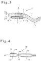
- Fig. 5 shows a third embodiment of the present invention in which the annular groove 111 formed in the plate 110 of the second embodiment is omitted to provide a flat plate.
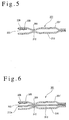
- Fig. 6 shows a fourth embodiment of the invention.
- the cylinder head gasket 201 comprises a pair of plates 201' and 210, but in the present embodiment, a single inner plate 313 is disposed between a pair of plates 301' and 310.
- a projecting step 313a which projects in the same direction as a shim 303 is formed around a combustion chamber opening formed in the inner plate 313.
- the projection height of the projecting step 313 is chosen to be equal to or slightly less than the projection height of the shim 303, whereby when the cylinder head gasket is held sandwiched between the cylinder head and the cylinder block, the shim 303 abuts against the projecting step 313a of the inner plate 313 which in turn abuts against a portion of the plate 310 which is located inward of the full bead 307.
- the arrangement is similar to the third embodiment.
- the fourth embodiment constructed in this manner is capable of achieving a similar functioning and effect as achieved by the third embodiment.
- the projection height of the shim may vary in the circumferential direction.
Landscapes
- Engineering & Computer Science (AREA)
- General Engineering & Computer Science (AREA)
- Mechanical Engineering (AREA)
- Gasket Seals (AREA)
Applications Claiming Priority (2)
| Application Number | Priority Date | Filing Date | Title |
|---|---|---|---|
| JP2000049862 | 2000-02-25 | ||
| JP2000049862A JP2001241551A (ja) | 2000-02-25 | 2000-02-25 | シリンダヘッドガスケット |
Publications (3)
| Publication Number | Publication Date |
|---|---|
| EP1128099A2 true EP1128099A2 (de) | 2001-08-29 |
| EP1128099A3 EP1128099A3 (de) | 2003-05-14 |
| EP1128099B1 EP1128099B1 (de) | 2005-02-02 |
Family
ID=18571731
Family Applications (1)
| Application Number | Title | Priority Date | Filing Date |
|---|---|---|---|
| EP01301499A Expired - Lifetime EP1128099B1 (de) | 2000-02-25 | 2001-02-20 | Zylinderkopfdichtung |
Country Status (4)
| Country | Link |
|---|---|
| US (1) | US6565097B2 (de) |
| EP (1) | EP1128099B1 (de) |
| JP (1) | JP2001241551A (de) |
| DE (1) | DE60108672T2 (de) |
Cited By (3)
| Publication number | Priority date | Publication date | Assignee | Title |
|---|---|---|---|---|
| US6796562B2 (en) | 2002-01-09 | 2004-09-28 | Federal-Mogul Sealing Systems | Cylinder head gasket that fills gaps arising from local depressions in the area of the pressure limiter |
| EP1510734A3 (de) * | 2003-08-28 | 2005-03-16 | Carl Freudenberg KG | Dichtung mit flexiblem Stopper |
| DE10353040B4 (de) * | 2003-11-13 | 2008-04-30 | Frenzelit-Werke Gmbh & Co Kg | Flachdichtung mit Fixiervorrichtung |
Families Citing this family (24)
| Publication number | Priority date | Publication date | Assignee | Title |
|---|---|---|---|---|
| JP2003035363A (ja) * | 2001-07-23 | 2003-02-07 | Ishikawa Gasket Co Ltd | シリンダヘッドガスケット |
| JP2004218740A (ja) * | 2003-01-15 | 2004-08-05 | Nichias Corp | 組み合わせ金属ガスケット及びシール構造体 |
| US7234705B2 (en) * | 2003-08-28 | 2007-06-26 | Freudenberg-Nok General Partnership | Sealing gasket with flexible stopper |
| CA2477342A1 (en) * | 2003-08-28 | 2005-02-28 | Freudenberg-Nok General Partnership | Improved sealing gasket with flexible stopper |
| US7200932B2 (en) * | 2004-01-13 | 2007-04-10 | Federal-Mogul Worldwide, Inc. | Laser welded multi-layered steel gasket assembly |
| JP3908745B2 (ja) * | 2004-03-09 | 2007-04-25 | 石川ガスケット株式会社 | 金属積層形ガスケット |
| MX2007000602A (es) * | 2004-07-16 | 2008-10-27 | Dana Corp | Abertura para fluido con reborde de estopero. |
| WO2006061042A1 (de) * | 2004-12-10 | 2006-06-15 | Elringklinger Ag | Flachdichtung |
| US20090033039A1 (en) * | 2005-06-28 | 2009-02-05 | Freudenberg-Nok General Partnership | Gasket with asymmetric bead arrangement |
| DE102006032895A1 (de) * | 2006-07-15 | 2008-01-24 | Elringklinger Ag | Flachdichtung |
| US20080143060A1 (en) * | 2006-12-15 | 2008-06-19 | Arvid Casler | Multi-layer gasket |
| JP4534097B2 (ja) * | 2007-09-12 | 2010-09-01 | 日本ガスケット株式会社 | シリンダヘッドガスケット |
| US8632077B2 (en) | 2008-02-13 | 2014-01-21 | Federal-Mogul Corporation | Multilayer static gasket with bead compression limiter |
| US20110127729A1 (en) * | 2008-09-18 | 2011-06-02 | Yasumaro Takeda | Cylinder head gasket |
| EP2344207B1 (de) * | 2008-09-22 | 2013-12-25 | Boston Scientific Neuromodulation Corporation | Implantierbare oder einführbare medizinische vorrichtungen |
| WO2011024812A1 (ja) * | 2009-08-26 | 2011-03-03 | Nok株式会社 | 金属ガスケット及び金属ガスケット用金型の製造方法 |
| KR101154403B1 (ko) * | 2009-12-03 | 2012-06-15 | 기아자동차주식회사 | 가스켓 유닛 |
| JP5061204B2 (ja) * | 2010-01-07 | 2012-10-31 | 株式会社豊田自動織機 | シリンダヘッドガスケット |
| JP5932213B2 (ja) * | 2010-11-12 | 2016-06-08 | 日本ガスケット株式会社 | シリンダヘッドガスケットの製造方法 |
| US9476382B2 (en) | 2012-08-10 | 2016-10-25 | Dana Automotive Systems Group, Llc | Multi-layered gasket |
| US9394850B2 (en) | 2012-08-10 | 2016-07-19 | Dana Automotive Systems Group, Llc | Metal gasket with coating topography |
| US9939066B2 (en) | 2013-03-14 | 2018-04-10 | Federal-Mogul Llc | Elastic sealing member radially inwardly of primary sealing bead |
| DE102015120782A1 (de) * | 2015-11-25 | 2017-06-01 | Elringklinger Ag | Flachdichtung sowie eine Flachdichtung enthaltender Dichtverband |
| KR20250072297A (ko) * | 2023-11-16 | 2025-05-23 | 현대자동차주식회사 | 차량의 배기계용 가스켓 |
Citations (1)
| Publication number | Priority date | Publication date | Assignee | Title |
|---|---|---|---|---|
| JPH09317890A (ja) | 1996-05-31 | 1997-12-12 | Nippon Reinz Co Ltd | メタルガスケット |
Family Cites Families (6)
| Publication number | Priority date | Publication date | Assignee | Title |
|---|---|---|---|---|
| DE3741344A1 (de) * | 1987-12-07 | 1989-06-15 | Yamaha Corp | Metalldichtung |
| JP3142155B2 (ja) * | 1991-08-21 | 2001-03-07 | 日本ガスケット株式会社 | 金属製ガスケット |
| DE69209009T2 (de) * | 1991-11-25 | 1996-08-29 | Taiho Kogyo Co Ltd | Metalldichtung |
| DE19756431C1 (de) * | 1997-12-18 | 1999-06-02 | Elringklinger Gmbh | Zylinderkopfdichtung sowie Verfahren zu deren Herstellung |
| DE19808544C2 (de) * | 1998-02-28 | 2000-02-03 | Elringklinger Gmbh | Zylinderkopfdichtung |
| DE29912950U1 (de) * | 1999-07-24 | 2000-01-27 | Federal-Mogul Sealing Systems GmbH, 57562 Herdorf | Metallische Flachdichtung |
-
2000
- 2000-02-25 JP JP2000049862A patent/JP2001241551A/ja active Pending
-
2001
- 2001-02-14 US US09/782,824 patent/US6565097B2/en not_active Expired - Lifetime
- 2001-02-20 DE DE60108672T patent/DE60108672T2/de not_active Expired - Fee Related
- 2001-02-20 EP EP01301499A patent/EP1128099B1/de not_active Expired - Lifetime
Patent Citations (1)
| Publication number | Priority date | Publication date | Assignee | Title |
|---|---|---|---|---|
| JPH09317890A (ja) | 1996-05-31 | 1997-12-12 | Nippon Reinz Co Ltd | メタルガスケット |
Cited By (4)
| Publication number | Priority date | Publication date | Assignee | Title |
|---|---|---|---|---|
| US6796562B2 (en) | 2002-01-09 | 2004-09-28 | Federal-Mogul Sealing Systems | Cylinder head gasket that fills gaps arising from local depressions in the area of the pressure limiter |
| DE10200544B4 (de) * | 2002-01-09 | 2005-04-28 | Federal Mogul Sealing Sys Spa | Zylinderkopfdichtung zum Ausgleich von lokalen Absenkungen im Bereich des Verpressungsbegrenzers |
| EP1510734A3 (de) * | 2003-08-28 | 2005-03-16 | Carl Freudenberg KG | Dichtung mit flexiblem Stopper |
| DE10353040B4 (de) * | 2003-11-13 | 2008-04-30 | Frenzelit-Werke Gmbh & Co Kg | Flachdichtung mit Fixiervorrichtung |
Also Published As
| Publication number | Publication date |
|---|---|
| DE60108672D1 (de) | 2005-03-10 |
| EP1128099B1 (de) | 2005-02-02 |
| JP2001241551A (ja) | 2001-09-07 |
| US20010017446A1 (en) | 2001-08-30 |
| US6565097B2 (en) | 2003-05-20 |
| DE60108672T2 (de) | 2006-05-11 |
| EP1128099A3 (de) | 2003-05-14 |
Similar Documents
| Publication | Publication Date | Title |
|---|---|---|
| EP1128099B1 (de) | Zylinderkopfdichtung | |
| US6076833A (en) | Metal gasket | |
| EP0987474B1 (de) | Zylinderkopfdichtung | |
| US5700017A (en) | Flanged rubber combustion seal | |
| US6827352B2 (en) | Metal gasket | |
| EP0533357B1 (de) | Metalldichtung | |
| US6283480B1 (en) | Metal gasket | |
| EP1207323B1 (de) | Zylinderkopfdichtung aus unterschiedlichen Werkstoffen | |
| US5671927A (en) | Gasket assembly with sealing member having main body with integral tabs | |
| US7997585B2 (en) | Cylinder head gasket | |
| US20100117306A1 (en) | Cylinder head gasket and engine | |
| US5341779A (en) | Beam functioning fire ring | |
| US6722662B2 (en) | Metallic cylinder head gasket | |
| US6994353B2 (en) | Metal gasket | |
| US5752480A (en) | Device for sealing a combustion chamber of a combustion engine | |
| US5988650A (en) | Multi-layered cylinder head gasket with compensating intermediate plate | |
| JP4110256B2 (ja) | 金属製ガスケット | |
| US20010026047A1 (en) | Laminated gasket | |
| EP1111277B1 (de) | Metallische Flachdichtung | |
| JP3971423B2 (ja) | シリンダヘッドガスケット | |
| JP2002005292A (ja) | 金属ガスケット | |
| JPH0346209Y2 (de) | ||
| JP4726293B2 (ja) | シリンダヘッドガスケット | |
| JPH10122370A (ja) | 金属ガスケット | |
| JP4712165B2 (ja) | 金属ガスケット |
Legal Events
| Date | Code | Title | Description |
|---|---|---|---|
| PUAI | Public reference made under article 153(3) epc to a published international application that has entered the european phase |
Free format text: ORIGINAL CODE: 0009012 |
|
| AK | Designated contracting states |
Kind code of ref document: A2 Designated state(s): AT BE CH CY DE DK ES FI FR GB GR IE IT LI LU MC NL PT SE TR |
|
| AX | Request for extension of the european patent |
Free format text: AL;LT;LV;MK;RO;SI |
|
| PUAL | Search report despatched |
Free format text: ORIGINAL CODE: 0009013 |
|
| AK | Designated contracting states |
Designated state(s): AT BE CH CY DE DK ES FI FR GB GR IE IT LI LU MC NL PT SE TR |
|
| AX | Request for extension of the european patent |
Extension state: AL LT LV MK RO SI |
|
| 17P | Request for examination filed |
Effective date: 20031021 |
|
| AKX | Designation fees paid |
Designated state(s): DE GB |
|
| GRAP | Despatch of communication of intention to grant a patent |
Free format text: ORIGINAL CODE: EPIDOSNIGR1 |
|
| GRAS | Grant fee paid |
Free format text: ORIGINAL CODE: EPIDOSNIGR3 |
|
| GRAA | (expected) grant |
Free format text: ORIGINAL CODE: 0009210 |
|
| AK | Designated contracting states |
Kind code of ref document: B1 Designated state(s): DE GB |
|
| REG | Reference to a national code |
Ref country code: GB Ref legal event code: FG4D |
|
| REG | Reference to a national code |
Ref country code: IE Ref legal event code: FG4D |
|
| REF | Corresponds to: |
Ref document number: 60108672 Country of ref document: DE Date of ref document: 20050310 Kind code of ref document: P |
|
| PLBE | No opposition filed within time limit |
Free format text: ORIGINAL CODE: 0009261 |
|
| STAA | Information on the status of an ep patent application or granted ep patent |
Free format text: STATUS: NO OPPOSITION FILED WITHIN TIME LIMIT |
|
| 26N | No opposition filed |
Effective date: 20051103 |
|
| PGFP | Annual fee paid to national office [announced via postgrant information from national office to epo] |
Ref country code: DE Payment date: 20090213 Year of fee payment: 9 |
|
| PGFP | Annual fee paid to national office [announced via postgrant information from national office to epo] |
Ref country code: GB Payment date: 20090217 Year of fee payment: 9 |
|
| GBPC | Gb: european patent ceased through non-payment of renewal fee |
Effective date: 20100220 |
|
| PG25 | Lapsed in a contracting state [announced via postgrant information from national office to epo] |
Ref country code: DE Free format text: LAPSE BECAUSE OF NON-PAYMENT OF DUE FEES Effective date: 20100901 |
|
| PG25 | Lapsed in a contracting state [announced via postgrant information from national office to epo] |
Ref country code: GB Free format text: LAPSE BECAUSE OF NON-PAYMENT OF DUE FEES Effective date: 20100220 |