EP0987474B1 - Zylinderkopfdichtung - Google Patents
Zylinderkopfdichtung Download PDFInfo
- Publication number
- EP0987474B1 EP0987474B1 EP99306546A EP99306546A EP0987474B1 EP 0987474 B1 EP0987474 B1 EP 0987474B1 EP 99306546 A EP99306546 A EP 99306546A EP 99306546 A EP99306546 A EP 99306546A EP 0987474 B1 EP0987474 B1 EP 0987474B1
- Authority
- EP
- European Patent Office
- Prior art keywords
- gasket
- cylinder head
- projection
- cylinder block
- cylinder
- Prior art date
- Legal status (The legal status is an assumption and is not a legal conclusion. Google has not performed a legal analysis and makes no representation as to the accuracy of the status listed.)
- Expired - Lifetime
Links
Images


Classifications
-
- F—MECHANICAL ENGINEERING; LIGHTING; HEATING; WEAPONS; BLASTING
- F16—ENGINEERING ELEMENTS AND UNITS; GENERAL MEASURES FOR PRODUCING AND MAINTAINING EFFECTIVE FUNCTIONING OF MACHINES OR INSTALLATIONS; THERMAL INSULATION IN GENERAL
- F16J—PISTONS; CYLINDERS; SEALINGS
- F16J15/00—Sealings
- F16J15/02—Sealings between relatively-stationary surfaces
- F16J15/06—Sealings between relatively-stationary surfaces with solid packing compressed between sealing surfaces
- F16J15/08—Sealings between relatively-stationary surfaces with solid packing compressed between sealing surfaces with exclusively metal packing
- F16J15/0818—Flat gaskets
- F16J15/0825—Flat gaskets laminated
-
- F—MECHANICAL ENGINEERING; LIGHTING; HEATING; WEAPONS; BLASTING
- F16—ENGINEERING ELEMENTS AND UNITS; GENERAL MEASURES FOR PRODUCING AND MAINTAINING EFFECTIVE FUNCTIONING OF MACHINES OR INSTALLATIONS; THERMAL INSULATION IN GENERAL
- F16J—PISTONS; CYLINDERS; SEALINGS
- F16J15/00—Sealings
- F16J15/02—Sealings between relatively-stationary surfaces
- F16J15/06—Sealings between relatively-stationary surfaces with solid packing compressed between sealing surfaces
- F16J15/08—Sealings between relatively-stationary surfaces with solid packing compressed between sealing surfaces with exclusively metal packing
- F16J15/0818—Flat gaskets
- F16J2015/085—Flat gaskets without fold over
-
- F—MECHANICAL ENGINEERING; LIGHTING; HEATING; WEAPONS; BLASTING
- F16—ENGINEERING ELEMENTS AND UNITS; GENERAL MEASURES FOR PRODUCING AND MAINTAINING EFFECTIVE FUNCTIONING OF MACHINES OR INSTALLATIONS; THERMAL INSULATION IN GENERAL
- F16J—PISTONS; CYLINDERS; SEALINGS
- F16J15/00—Sealings
- F16J15/02—Sealings between relatively-stationary surfaces
- F16J15/06—Sealings between relatively-stationary surfaces with solid packing compressed between sealing surfaces
- F16J15/08—Sealings between relatively-stationary surfaces with solid packing compressed between sealing surfaces with exclusively metal packing
- F16J15/0818—Flat gaskets
- F16J2015/0856—Flat gaskets with a non-metallic coating or strip
-
- F—MECHANICAL ENGINEERING; LIGHTING; HEATING; WEAPONS; BLASTING
- F16—ENGINEERING ELEMENTS AND UNITS; GENERAL MEASURES FOR PRODUCING AND MAINTAINING EFFECTIVE FUNCTIONING OF MACHINES OR INSTALLATIONS; THERMAL INSULATION IN GENERAL
- F16J—PISTONS; CYLINDERS; SEALINGS
- F16J15/00—Sealings
- F16J15/02—Sealings between relatively-stationary surfaces
- F16J15/06—Sealings between relatively-stationary surfaces with solid packing compressed between sealing surfaces
- F16J15/08—Sealings between relatively-stationary surfaces with solid packing compressed between sealing surfaces with exclusively metal packing
- F16J15/0818—Flat gaskets
- F16J2015/0875—Flat gaskets comprising welds
Definitions
- a cylinder head gasket including first and second gasket substrates disposed in overlapping relationship for location between a cylinder head and a cylinder block of an engine and each having a combustion chamber opening formed therein for alignment with a cylinder bore in the cylinder block, the first gasket substrate for location adjacent the cylinder head being formed with a first inner projection surrounding the combustion chamber opening and, in use, projecting towards the cylinder head, and the second gasket substrate for location adjacent the cylinder block being formed with a second inner projection surrounding the combustion chamber opening and, in use, projecting towards the cylinder block, the first and the second gasket substrates being disposed in overlapping relationship to define a clearance between the first and the second inner projections, the arrangement being such that, when the first and the second gasket substrates are assembled into an engine to be held sandwiched between the cylinder head and the cylinder block, the first and the second inner projections are plastically deformed towards the clearance defined therebetween, characterised by a first plate and a second plate on the front and the back
- both inner projections will undergo a magnitude of plastic deformation which varies in accordance with the surface pressure, with the consequence that there is secured an even pressure of contact, enabling local blow-through to be prevented.
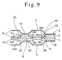
- a cylinder head gasket 1 comprises a first gasket substrate 2 and a second gasket substrate 3 of a relatively increased thickness which are disposed in overlapping relationship.
- a first plate 4 and a second plate 5 of a relatively reduced thickness are disposed in overlapping relationship with the front and the back surface of the assembly of gasket substrates.
- four combustion chamber openings 10 are formed through the gasket substrates 2,3 and the plates 4, 5 in alignment with a cylinder bore 9 of an engine as are bolt holes 11 for passing clamping bolts, not shown, and water holes 12 through which a cooling water is passed.
- the gasket substrates 2, 3 and the plates 4, 5 are integrally fastened together by means such as lancelock.
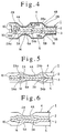
- the first and the second outer projection 2B, 3B are also formed symmetrically to each other with respect to a mating surface between the both gasket substrates 2, 3, whereby when the both gasket substrates 2, 3 are disposed in overlapping relationship, a clearance or an air gap 15 (see Fig.4) can be defined between the first and the second outer projection 2B, 3B which project in opposite directions.
- the air gap 15 will be formed between the sidewalls 2Ba, 3Ba which are adjacent to each other, as shown in Fig. 3, but the inner surfaces of the both outer projections 2B, 3B which are formed as recesses will contact each other in regions other than the region between the pair of adjacent combustion chamber openings 10.
- the air gap 15 is formed in an extent lying between the sidewalls 2Ba, 3Ba to an area of contact between the both recessed surfaces.
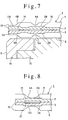
- the cylinder block 13 is provided with a liner 16, as shown in Figs. 2 and 3, and the liner 16 is formed with a flange 16A at its top end which extends radially outward.
- the liner 16 is secured as a press fit in the cylinder block 13, and the bottom surface of the flange 16A is disposed in abutment against the upper surface of an offset step 13A formed in the cylinder block 13, thereby positioning the liner 16 on the cylinder block 13.
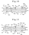
- FIG. 11 shows a corresponding cross section taken at a position which is close to a bolt hole through which a clamping bolt is passed.
- the first projection 102A and the second inner projection 103A have a reduced height h2 and a reduced angle of rise ⁇ 2 along the inner and outer peripheries.
- the heights h1, h2 and angles ⁇ 1, ⁇ 2, prevail over a given extent centered about the intermediate position between the bolt holes and the position close to the bolt hole, with both the height and the angle smoothly changing from one of the values to the other.
- any combustion gas which tends to blow through a clearance between the first inner projection 102A and the second inner projection 103A to the exterior exhibits a pressure which urges the first inner projection 102A toward the cylinder head and which simultaneously urges the second inner projection 103A toward the cylinder block.
- the surface pressure acting between the first inner projection and the cylinder head then increases, thus improving the sealing performance of such region.
- the surface pressure acting between the second inner projection and the cylinder block increases, also improving the sealing performance in such region.
Landscapes
- Engineering & Computer Science (AREA)
- General Engineering & Computer Science (AREA)
- Mechanical Engineering (AREA)
- Gasket Seals (AREA)
Claims (12)
- Zylinderkopfdichtung (1), umfassend ein erstes und ein zweites Dichtungssubstrat (2, 3), die in überlappender Beziehung zueinander zur Anordnung zwischen einem Zylinderkopf und einem Zylinderblock (13) eines Motors angeordnet sind und zur fluchtenden Ausrichtung mit einer Zylinderbohrung (9) im Zylinderblock (13) jeweils eine in diesem ausgebildete Verbrennungskammeröffnung (10) aufweisen, wobei das erste Dichtungssubstrat (2) zur anliegenden Anordnung am Zylinderkopf mit einem ersten inneren Vorsprung (2A) um die Verbrennungskammeröffnung (10) herum gebildet ist, der im Betrieb in Richtung Zylinderkopf vorsteht, und das zweite Dichtungssubstrat (3) zur anliegenden Anordnung am Zylinderblock (13) mit einem zweiten inneren Vorsprung (3A) um die Verbrennungskammeröffnung (10) herum gebildet ist, der im Betrieb in Richtung Zylinderblock vorsteht, wobei das erste und zweite Dichtungssubstrat (2, 3) in überlappender Beziehung zueinander angeordnet sind, um einen Zwischenraum (14) zwischen dem ersten und dem zweiten inneren Vorsprung (2A, 3A) zu definieren, wobei die Anordnung so ist, dass wenn das erste und das zweite Dichtungssubstrat (2, 3) in einem Motor eingebaut sind, um zwischen dem Zylinderkopf und dem Zylinderblock (13) eingeschoben zu sein, der erste und der zweite innere Vorsprung (2A, 3A) in Richtung des zwischen ihnen definierten Zwischenraumes (14) plastisch verformt werden, gekennzeichnet durch eine erste Platte (4) und eine zweite Platte (5) auf gegenüberliegenden Seiten des zusammengesetzten Paars der Dichtungssubstrate (2, 3), wobei jede Platte (4, 5) zur fluchtenden Ausrichtung mit der Zylinderbohrung (9) eine in dieser ausgebildete Verbrennungskammeröffnung (10) umfasst, und wobei die erste Platte (4), die in überlappender Beziehung mit dem ersten Dichtungssubstrat (2) angeordnet ist, mit einer ersten Voll-Randwulst (4A) um die Verbrennungskammeröffnung (10) herum gebildet ist, die in Richtung des ersten inneren Vorsprungs (2A) vorsteht, und die zweite Platte (5), die in überlappender Beziehung mit dem zweiten Dichtungssubstrat (3) angeordnet ist, mit einer zweiten Voll-Randwulst (5A) um die Verbrennungskammeröffnung (10) herum ausgebildet ist, die in Richtung des zweiten inneren Vorsprungs (3A) vorsteht.
- Zylinderkopfdichtung nach Anspruch 1, worin das erste Dichtungssubstrat (2) mit einem ersten äußeren Vorsprung (2B) um den ersten inneren Vorsprungs (2A) herum gebildet ist, der im Betrieb in Richtung des Zylinderkopfes vorsteht, und worin das zweite Dichtungssubstrat (3) mit einem zweiten äußeren Vorsprung (3B) um den zweiten inneren Vorsprung (2B) herum gebildet ist, der beim Betrieb in Richtung des Zylinderblockes (13) vorsteht, wobei das erste und das zweite Dichtungssubstrat (2, 3) in überlappender Beziehung zueinander angeordnet sind, um einen Zwischenraum (15) zwischen dem ersten und dem zweiten äußeren Vorsprung (2B, 3B), die in entgegengesetzten Richtungen vorstehen, zu definieren.
- Zylinderkopfdichtung nach Anspruch 3, worin das erste und das zweite Dichtungssubstrat (2, 3) im Betrieb zwischen dem Zylinderkopf und dem Zylinderblock (13) eingeschoben gehalten sind, um eine plastische Verformung des ersten und des zweiten äußeren Vorsprungs (2B, 3B) in Richtung des zwischen ihnen definierten Zwischenraumes (15) zu bewirken.
- Zylinderkopfdichtung nach Anspruch 2 oder Anspruch 3, worin die erste Platte (4) mit einer ersten Halb-Randwulst (4B) gebildet ist, die außerhalb der ersten Voll-Randwulst (4A) angeordnet ist und in Richtung des ersten äußeren Vorsprungs (2B) vorsteht, und die zweite Platte (5) mit einer zweiten Halb-Randwulst (5B) gebildet ist, die außerhalb der zweiten Voll-Randwulst (5A) angeordnet ist und in Richtung des zweiten äußeren Vorsprungs (3B) vorsteht.
- Zylinderkopfdichtung nach einem der Ansprüche 2 bis 4, worin bei jedem Dichtungssubstrat (2, 3) das Ausmaß des Überstands des inneren Vorsprungs (2A, 3A) größer als das Ausmaß des Überstands des äußeren Vorsprungs (2B, 3B) ist.
- Zylinderkopfdichtung nach einem der Ansprüche 2 bis 5, worin der innere Vorsprung (2A, 3A) einen Anstiegswinkel (f) vom zugeordneten Dichtungssubstrat (2, 3) aufweist, der größer als der Anstiegswinkel (h) des äußeren Vorsprungs (2B, 3B) vom Dichtungssubstrat (2, 3) gewählt ist.
- Zylinderkopfdichtung nach einem der Ansprüche 1 bis 6, worin eine Beilagscheibe (21) an der inneren Oberfläche von zumindest einem aus dem ersten und dem zweiten inneren Vorsprung (2A, 3A) bereitgestellt ist.
- Zylinderkopfdichtung nach einem der Ansprüche 1 bis 6, worin eine abgeschrägte Schicht an der inneren Oberfläche von zumindest einem aus dem ersten und dem zweiten inneren Vorsprung (2A, 3A) ausgebildet ist.
- Zylinderkopfdichtung nach einem der Ansprüche 1 bis 6, worin eine Harzschicht an der inneren Oberfläche von zumindest einem aus dem ersten und dem zweiten inneren Vorsprung (2A, 3A) ausgebildet ist.
- Zylinderkopfdichtung nach einem der Ansprüche 1 bis 9, worin das Ausmaß des Überstands des ersten und des zweiten inneren Vorsprungs (2A, 3A) in einem Bereich der Dichtung, der sich im Betrieb in der Nähe eines Befestigungsbolzens befindet, der zum Aneinanderklemmen des Zylinderkopfs an den Zylinderblock (13) verwendet wird, klein gewählt ist, und in einem Bereich der Dichtung, der sich im Betrieb an einer Stelle fern vom Befestigungsbolzen befindet, größer gewählt ist.
- Zylinderkopfdichtung nach einem der Ansprüche 1 bis 10, worin der erste und der zweite innere Vorsprung (2A, 3A) eine Breite aufweisen, die in einem Bereich der Dichtung, der sich im Betrieb in der Nähe eines Befestigungsbolzen befindet, der zum Aneinanderklemmen des Zylinderkopfs und des Zylinderblocks (13) verwendet wird, breiter ist, und in einem Bereich der Dichtung, der sich im Betrieb an einer Stelle fern vom Befestigungsbolzen befindet, schmaler ist.
- Zylinderkopfdichtung nach einem der Ansprüche 1 bis 11, worin der erste und der zweite innere Vorsprung (2A, 3A) einen Anstiegswinkel () vom jeweiligen zugeordneten Dichtungssubstrat (2, 3) aufweisen, der in einem Bereich der Dichtung, der sich im Betrieb in der Nähe eines Befestigungsbolzen befindet, der zum Aneinanderklemmen des Zylinderkopfs und des Zylinderblocks (13) verwendet wird, klein ist, und in einem Bereich der Dichtung, der sich im Betrieb an einer Stelle fern vom Befestigungsbolzen befindet, größer gewählt ist.
Priority Applications (1)
| Application Number | Priority Date | Filing Date | Title |
|---|---|---|---|
| EP03025966A EP1398546B1 (de) | 1998-09-18 | 1999-08-19 | Zylinderkopfdichtung |
Applications Claiming Priority (2)
| Application Number | Priority Date | Filing Date | Title |
|---|---|---|---|
| JP26426398A JP4032270B2 (ja) | 1998-09-18 | 1998-09-18 | シリンダヘッドガスケット |
| JP26426398 | 1998-09-18 |
Related Child Applications (2)
| Application Number | Title | Priority Date | Filing Date |
|---|---|---|---|
| EP03025966A Division EP1398546B1 (de) | 1998-09-18 | 1999-08-19 | Zylinderkopfdichtung |
| EP03025966.7 Division-Into | 2003-11-13 |
Publications (3)
| Publication Number | Publication Date |
|---|---|
| EP0987474A2 EP0987474A2 (de) | 2000-03-22 |
| EP0987474A3 EP0987474A3 (de) | 2000-10-25 |
| EP0987474B1 true EP0987474B1 (de) | 2004-10-27 |
Family
ID=17400750
Family Applications (2)
| Application Number | Title | Priority Date | Filing Date |
|---|---|---|---|
| EP03025966A Expired - Lifetime EP1398546B1 (de) | 1998-09-18 | 1999-08-19 | Zylinderkopfdichtung |
| EP99306546A Expired - Lifetime EP0987474B1 (de) | 1998-09-18 | 1999-08-19 | Zylinderkopfdichtung |
Family Applications Before (1)
| Application Number | Title | Priority Date | Filing Date |
|---|---|---|---|
| EP03025966A Expired - Lifetime EP1398546B1 (de) | 1998-09-18 | 1999-08-19 | Zylinderkopfdichtung |
Country Status (4)
| Country | Link |
|---|---|
| US (2) | US6328314B1 (de) |
| EP (2) | EP1398546B1 (de) |
| JP (1) | JP4032270B2 (de) |
| DE (2) | DE69921411T2 (de) |
Families Citing this family (38)
| Publication number | Priority date | Publication date | Assignee | Title |
|---|---|---|---|---|
| JP4032270B2 (ja) * | 1998-09-18 | 2008-01-16 | 大豊工業株式会社 | シリンダヘッドガスケット |
| JP3751786B2 (ja) * | 1999-12-27 | 2006-03-01 | 石川ガスケット株式会社 | 金属積層形ガスケット |
| DE10015604C2 (de) * | 2000-03-29 | 2003-10-30 | Reinz Dichtungs Gmbh | Metallische Flachdichtung |
| RU2273778C2 (ru) * | 2000-06-15 | 2006-04-10 | Райнц-Дихтунгс-Гмбх | Плоская прокладка и способ ее изготовления |
| JP2002081543A (ja) * | 2000-09-04 | 2002-03-22 | Nippon Gasket Co Ltd | 金属製ガスケット |
| DE10050478B4 (de) * | 2000-10-12 | 2009-08-06 | Reinz-Dichtungs-Gmbh | Mehrlagenstahldichtung |
| DE20021017U1 (de) * | 2000-12-12 | 2001-02-22 | REINZ Dichtungs GmbH u. Co. KG, 89233 Neu-Ulm | Zylinderkopfdichtung |
| JP3885959B2 (ja) * | 2001-03-07 | 2007-02-28 | 日本メタルガスケット株式会社 | 金属ガスケット |
| DE10143431B4 (de) * | 2001-09-05 | 2006-02-02 | Elringklinger Ag | Zylinderkopfdichtung |
| DE10218245A1 (de) | 2002-04-24 | 2003-11-13 | Elringklinger Ag | Zylinderkopfdichtung |
| JP3769549B2 (ja) * | 2003-03-26 | 2006-04-26 | 石川ガスケット株式会社 | メタルガスケット |
| CA2477342A1 (en) * | 2003-08-28 | 2005-02-28 | Freudenberg-Nok General Partnership | Improved sealing gasket with flexible stopper |
| US20050046120A1 (en) * | 2003-08-28 | 2005-03-03 | Martin Novil | Sealing gasket with flexible stopper |
| US7234705B2 (en) * | 2003-08-28 | 2007-06-26 | Freudenberg-Nok General Partnership | Sealing gasket with flexible stopper |
| JP2005195139A (ja) * | 2004-01-09 | 2005-07-21 | Ishikawa Gasket Co Ltd | シリンダヘッドガスケット |
| JP3908745B2 (ja) * | 2004-03-09 | 2007-04-25 | 石川ガスケット株式会社 | 金属積層形ガスケット |
| WO2006020041A1 (en) * | 2004-07-16 | 2006-02-23 | Dana Corporation A Corporation Of Virginia | Fluid aperture with stopper bead |
| DE102004044851A1 (de) * | 2004-09-10 | 2006-03-16 | Elringklinger Ag | Zylinderkopfdichtung |
| DE102004056638A1 (de) * | 2004-11-24 | 2006-10-12 | Federal-Mogul Sealing Systems Gmbh | Flachdichtung |
| JP2006242294A (ja) * | 2005-03-03 | 2006-09-14 | Ishikawa Gasket Co Ltd | 金属積層形シリンダヘッドガスケット |
| DE102005019689A1 (de) * | 2005-04-28 | 2006-11-16 | Elringklinger Ag | Flachdichtung, insbesondere Zylinderkopfdichtung |
| DE102005020923A1 (de) * | 2005-05-04 | 2006-11-16 | Federal-Mogul Sealing Systems Gmbh | Flachdichtung, insbesondere Zylinderkopfdichtung |
| US20090033039A1 (en) * | 2005-06-28 | 2009-02-05 | Freudenberg-Nok General Partnership | Gasket with asymmetric bead arrangement |
| JP4714699B2 (ja) * | 2007-01-16 | 2011-06-29 | 内山工業株式会社 | ガスケット |
| JP4534097B2 (ja) | 2007-09-12 | 2010-09-01 | 日本ガスケット株式会社 | シリンダヘッドガスケット |
| US8632077B2 (en) * | 2008-02-13 | 2014-01-21 | Federal-Mogul Corporation | Multilayer static gasket with bead compression limiter |
| DE102008020277B4 (de) * | 2008-04-23 | 2016-06-30 | Elringklinger Ag | Zylinderkopfdichtung |
| US20110127729A1 (en) * | 2008-09-18 | 2011-06-02 | Yasumaro Takeda | Cylinder head gasket |
| KR101509784B1 (ko) * | 2009-09-03 | 2015-04-06 | 현대자동차주식회사 | 차량의 배기관용 가스켓 |
| US8336888B2 (en) * | 2009-10-22 | 2012-12-25 | Dana Automotive Systems Group, Llc | Gasket with engine liner accomodation |
| KR101154403B1 (ko) * | 2009-12-03 | 2012-06-15 | 기아자동차주식회사 | 가스켓 유닛 |
| US20120175847A1 (en) * | 2011-01-12 | 2012-07-12 | Popielas Frank W | Support wave stopper in web area of multi-layered steel cylinder head gasket |
| US9394850B2 (en) * | 2012-08-10 | 2016-07-19 | Dana Automotive Systems Group, Llc | Metal gasket with coating topography |
| US9476382B2 (en) * | 2012-08-10 | 2016-10-25 | Dana Automotive Systems Group, Llc | Multi-layered gasket |
| WO2015109171A1 (en) * | 2014-01-17 | 2015-07-23 | Federal-Mogul Corporation | Gasket component with half-stop and method of manufacturing |
| DE102014100948A1 (de) * | 2014-01-28 | 2015-07-30 | Elringklinger Ag | Zylinderkopfdichtung sowie ein eine solche umfassendes Abdichtsystem |
| DE102015120782A1 (de) * | 2015-11-25 | 2017-06-01 | Elringklinger Ag | Flachdichtung sowie eine Flachdichtung enthaltender Dichtverband |
| US20220243815A1 (en) * | 2021-02-02 | 2022-08-04 | Tenneco Inc. | Combustion cylinder head gasket |
Family Cites Families (29)
| Publication number | Priority date | Publication date | Assignee | Title |
|---|---|---|---|---|
| US3835524A (en) * | 1973-08-13 | 1974-09-17 | Massey Welding Co | Method of manufacturing rejuvenated scarfing blocks |
| US4428593A (en) * | 1981-07-10 | 1984-01-31 | Felt Products Mfg. Co. | Gasket assembly having improved sealing characteristics and method of making same |
| JPS62155375A (ja) | 1985-12-27 | 1987-07-10 | Nippon Metal Gasket Kk | 金属ガスケツト |
| JP2523321B2 (ja) | 1987-05-27 | 1996-08-07 | 日本メタルガスケット株式会社 | 積層金属ガスケット |
| JP2610891B2 (ja) | 1987-09-11 | 1997-05-14 | 日本メタルガスケット株式会社 | 積層金属ガスケット |
| JPH0261171A (ja) | 1988-06-10 | 1990-03-01 | Mitsuo Fujisawa | 布素材に於ける縁飾り切口の構造とその加工装置 |
| JPH01118149A (ja) | 1988-09-30 | 1989-05-10 | Ricoh Co Ltd | 画像記録方法 |
| US5205566A (en) * | 1989-04-14 | 1993-04-27 | Nihon Metal Gasket Kabushiki Kaisha | Metallic gasket |
| JPH0536135Y2 (de) * | 1990-02-01 | 1993-09-13 | ||
| JP2521155Y2 (ja) * | 1990-08-07 | 1996-12-25 | 石川ガスケット 株式会社 | 断熱性金属積層形ガスケット |
| JPH051771A (ja) * | 1991-01-11 | 1993-01-08 | Japan Metal Gasket Co Ltd | 金属ガスケツト |
| JP3054457B2 (ja) | 1991-04-03 | 2000-06-19 | 大豊工業株式会社 | 金属ガスケット |
| JP3126418B2 (ja) | 1991-07-08 | 2001-01-22 | トヨタ自動車株式会社 | 金属ガスケット |
| JP3083375B2 (ja) * | 1991-10-15 | 2000-09-04 | 日本ガスケット株式会社 | エキゾーストマニホルドガスケット等のガスケット |
| JP3118043B2 (ja) | 1991-10-24 | 2000-12-18 | 大豊工業株式会社 | 金属ガスケット |
| DE4238669C2 (de) * | 1992-11-17 | 1999-02-11 | Kempchen & Co Gmbh | Absperrarmatur |
| JP3197395B2 (ja) * | 1993-01-14 | 2001-08-13 | 日本メタルガスケット株式会社 | 金属ガスケット |
| JPH07253160A (ja) * | 1994-03-14 | 1995-10-03 | Nippon Riikuresu Kogyo Kk | メタルガスケット |
| JPH07253162A (ja) * | 1994-06-30 | 1995-10-03 | Nippon Riikuresu Kogyo Kk | メタルガスケット |
| JP3489755B2 (ja) | 1994-08-05 | 2004-01-26 | 日本ガスケット株式会社 | 金属製ガスケット |
| JP2920597B2 (ja) | 1994-10-17 | 1999-07-19 | 株式会社ケットアンドケット | 金属ガスケット |
| BR9505567A (pt) * | 1995-04-26 | 1997-11-04 | Elringklinger Gmbh | Vedação metálica de cabeçote |
| EP0773392B1 (de) * | 1995-11-07 | 2004-12-15 | Nicholsons Aircraft Seals Limited | Abdichtung |
| DE19605871C2 (de) * | 1996-02-17 | 1998-01-29 | Elringklinger Gmbh | Metallische Zylinderkopfdichtung |
| US6145847A (en) * | 1997-01-13 | 2000-11-14 | Nippon Reinz Co., Ltd. | Metal laminate gasket |
| US5979906A (en) * | 1997-02-13 | 1999-11-09 | Farnam/Meillor Sealing Systems Inc. | Multi-layered metal gasket assembly and method of constructing the same |
| US5906376A (en) * | 1997-04-24 | 1999-05-25 | Ishikawa Gasket Co., Ltd. | Metal gasket with locally heated-treating bead |
| DE19731489C2 (de) * | 1997-07-22 | 2001-09-20 | Reinz Dichtungs Gmbh | Metallische Flachdichtung |
| JP4032270B2 (ja) * | 1998-09-18 | 2008-01-16 | 大豊工業株式会社 | シリンダヘッドガスケット |
-
1998
- 1998-09-18 JP JP26426398A patent/JP4032270B2/ja not_active Expired - Fee Related
-
1999
- 1999-08-16 US US09/374,867 patent/US6328314B1/en not_active Expired - Fee Related
- 1999-08-19 DE DE69921411T patent/DE69921411T2/de not_active Expired - Lifetime
- 1999-08-19 EP EP03025966A patent/EP1398546B1/de not_active Expired - Lifetime
- 1999-08-19 EP EP99306546A patent/EP0987474B1/de not_active Expired - Lifetime
- 1999-08-19 DE DE69926552T patent/DE69926552T2/de not_active Expired - Lifetime
-
2001
- 2001-09-26 US US09/963,309 patent/US6705618B2/en not_active Expired - Fee Related
Also Published As
| Publication number | Publication date |
|---|---|
| DE69921411D1 (de) | 2004-12-02 |
| US20020011709A1 (en) | 2002-01-31 |
| DE69926552D1 (de) | 2005-09-08 |
| US6328314B1 (en) | 2001-12-11 |
| EP0987474A3 (de) | 2000-10-25 |
| JP2000088105A (ja) | 2000-03-31 |
| EP1398546B1 (de) | 2005-08-03 |
| US6705618B2 (en) | 2004-03-16 |
| DE69921411T2 (de) | 2005-10-20 |
| DE69926552T2 (de) | 2006-06-08 |
| JP4032270B2 (ja) | 2008-01-16 |
| EP0987474A2 (de) | 2000-03-22 |
| EP1398546A1 (de) | 2004-03-17 |
Similar Documents
| Publication | Publication Date | Title |
|---|---|---|
| EP0987474B1 (de) | Zylinderkopfdichtung | |
| EP0574166B1 (de) | Metalldichtung | |
| EP0533357B1 (de) | Metalldichtung | |
| US6619666B1 (en) | Metal gasket assembly | |
| EP0544215B1 (de) | Metalldichtung | |
| US6827352B2 (en) | Metal gasket | |
| US6565097B2 (en) | Cylinder head gasket | |
| EP0809051B1 (de) | Mehrlagenmetalldichtung mit partiellen Wülsten | |
| JP2008039181A (ja) | 停止作動型シリンダ・ヘッド・ガスケット | |
| US5626348A (en) | Metal gasket | |
| JPH1137296A (ja) | 金属製ガスケット | |
| US5803462A (en) | MLS gasket with yieldable combustion seal | |
| EP0892199B1 (de) | Mehrlagenmetalldichtung mit breiten und schmalen Flanschabschnitten | |
| EP1098114B1 (de) | Metallische Zylinderkopfdichtung | |
| US7753378B2 (en) | Cylinder head gasket | |
| JP4127726B2 (ja) | シリンダヘッドガスケット | |
| US5988650A (en) | Multi-layered cylinder head gasket with compensating intermediate plate | |
| JP4110256B2 (ja) | 金属製ガスケット | |
| MXPA04007947A (es) | Junta mls con talon obturador en el borde de la perforacion. | |
| JP3700960B2 (ja) | シリンダヘッドガスケット | |
| JPH0741137U (ja) | メタルガスケット | |
| EP0908648B1 (de) | Metallflachdichtung mit breiten und schmalen Flanschteilen | |
| JP2002005292A (ja) | 金属ガスケット | |
| JPH08226348A (ja) | シリンダライナとシリンダブロックの結合方法 | |
| JPH07119838A (ja) | シリンダヘッドガスケット |
Legal Events
| Date | Code | Title | Description |
|---|---|---|---|
| PUAI | Public reference made under article 153(3) epc to a published international application that has entered the european phase |
Free format text: ORIGINAL CODE: 0009012 |
|
| AK | Designated contracting states |
Kind code of ref document: A2 Designated state(s): DE FR GB |
|
| AX | Request for extension of the european patent |
Free format text: AL;LT;LV;MK;RO;SI |
|
| PUAL | Search report despatched |
Free format text: ORIGINAL CODE: 0009013 |
|
| AK | Designated contracting states |
Kind code of ref document: A3 Designated state(s): AT BE CH CY DE DK ES FI FR GB GR IE IT LI LU MC NL PT SE |
|
| AX | Request for extension of the european patent |
Free format text: AL;LT;LV;MK;RO;SI |
|
| 17P | Request for examination filed |
Effective date: 20001204 |
|
| AKX | Designation fees paid |
Free format text: DE FR GB |
|
| 17Q | First examination report despatched |
Effective date: 20030718 |
|
| GRAP | Despatch of communication of intention to grant a patent |
Free format text: ORIGINAL CODE: EPIDOSNIGR1 |
|
| GRAS | Grant fee paid |
Free format text: ORIGINAL CODE: EPIDOSNIGR3 |
|
| GRAA | (expected) grant |
Free format text: ORIGINAL CODE: 0009210 |
|
| AK | Designated contracting states |
Kind code of ref document: B1 Designated state(s): DE FR GB |
|
| REG | Reference to a national code |
Ref country code: GB Ref legal event code: FG4D |
|
| REF | Corresponds to: |
Ref document number: 69921411 Country of ref document: DE Date of ref document: 20041202 Kind code of ref document: P |
|
| ET | Fr: translation filed | ||
| PLBE | No opposition filed within time limit |
Free format text: ORIGINAL CODE: 0009261 |
|
| STAA | Information on the status of an ep patent application or granted ep patent |
Free format text: STATUS: NO OPPOSITION FILED WITHIN TIME LIMIT |
|
| 26N | No opposition filed |
Effective date: 20050728 |
|
| REG | Reference to a national code |
Ref country code: GB Ref legal event code: 746 Effective date: 20070821 |
|
| PGFP | Annual fee paid to national office [announced via postgrant information from national office to epo] |
Ref country code: FR Payment date: 20100824 Year of fee payment: 12 Ref country code: DE Payment date: 20100812 Year of fee payment: 12 |
|
| PGFP | Annual fee paid to national office [announced via postgrant information from national office to epo] |
Ref country code: GB Payment date: 20100818 Year of fee payment: 12 |
|
| GBPC | Gb: european patent ceased through non-payment of renewal fee |
Effective date: 20110819 |
|
| REG | Reference to a national code |
Ref country code: FR Ref legal event code: ST Effective date: 20120430 |
|
| REG | Reference to a national code |
Ref country code: DE Ref legal event code: R119 Ref document number: 69921411 Country of ref document: DE Effective date: 20120301 |
|
| PG25 | Lapsed in a contracting state [announced via postgrant information from national office to epo] |
Ref country code: FR Free format text: LAPSE BECAUSE OF NON-PAYMENT OF DUE FEES Effective date: 20110831 Ref country code: GB Free format text: LAPSE BECAUSE OF NON-PAYMENT OF DUE FEES Effective date: 20110819 |
|
| PG25 | Lapsed in a contracting state [announced via postgrant information from national office to epo] |
Ref country code: DE Free format text: LAPSE BECAUSE OF NON-PAYMENT OF DUE FEES Effective date: 20120301 |